Unit – 2
Connections
Introduction
In engineering, a connection serving to sign up for the man or woman participants of a shape, to make certain the reliability of the shape, and to offer for the right functioning of the shape as an entire in accord with the necessities of use and assembly.
The metallic systems are built through well connecting the to be had fashionable sections. The connections are a vital a part of metallic shape and are designed greater conventionally than any man or woman participants. There is a discrepancy among the real conduct and the evaluation of metallic shape is large, consequently the connections are complicated to research and layout. When the structural member fails in case of overloading then there may be a fashionable exercise to pick the man or woman member as opposed to the connections, consequently this form of exercise influences many structural participants. The fee of structural metallic includes main part of connections and this is the purpose number one significance ought to take delivery of to the layout of connections for protection and economy of shape.
The connections are commonly supplied withinside the following cases:
The category withinside the connections supplied withinside the metallic shape is as follows:
Riveted connections:
The riveted connections are these days obsolete. The know-how of this kind of connections for the power assessment and rehabilitation for an older shape is essential. While the relationship technique for riveted connections is equal as that of the bolted connections.
Rivet:
A rivet is made of spherical ductile metallic bar that is known as etc. ‘shank’ and with a head at the only quit. It is made of moderate metallic or excessive tensile metallic.
Riveting:
Riveting is the unique technique of connecting collectively portions of metallic. This technique is carried out through putting the ductile metallic pins known as etc. rivet into the holes of portions to be joined and shaped a head on the quit of the rivet to prevent every metallic piece from coming out.
The shank of the rivet is made of the period to the quantity via the unique elements that is to be linked and with enough greater period for a second head to be made at the opposite quit.
The rivets are commonly categorised as follows:
Clamp movement:
When warm pushed rivets are well cooled down then the diameter and shank period get reduced. Because of this, the compression of the plates happens and that outcomes in friction among the plates, this technique is known as categorized clamp movement.
Disadvantages of riveted connections are as follows:
Bolted Connection:
Most generally used connections consist of the bolted connections. This connection has the benefit of pliability in assembling elements of the shape as well as dissembling it and that is vital if there may be inspection or a few routine maintenances. This kind of connections is relevant for participants subjected to anxiety or shear or each anxiety and shear.
A bolt is a metallic pin with a head shaped at one quit and the shank threaded on the different quit in order that nut may be received. Generally, the bolts are used to attach the portions of metals through putting them via the holes withinside the metals; on the threaded quit, nuts ought to be tightened.
The blessings of bolted connections are as follows:
The risks of bolted connections are as follows:
Classification of bolted connections:
The classifications of bolted connections are made on the premise of resultant pressure transferred, kind of pressure and pressure mechanism.
On the premise of resultant pressure transferred:
On the premise of kind of pressure:
On the premise of pressure mechanism:
The layout philosophy:
The traditional technique to research the relationship is primarily based totally at the following conditions:
In sensible situations, the linked sections like angles, gusset plates, etc. are bendy deformation happens on the low depth of load also.
The bearing pressure performing at the bolt is proven at (c) and the shear pressure at (d) and (e). The most shear performing at the bolt, P, happens on the touch surface of the plates. The shear pressure at the bolt on the vital shear aircraft is
Fv= P/Ab
where Ab is nominal cross-sectional place of the bolt = pie*d2/4
The slip-vital bolt proven in Fig. 10.3a, relies upon Fl the friction brought about among the linked elements through the clamping movement of the pretensioned bolts to switch the burden from one linked part to another. No slip happens at carrier hundreds and, as proven at (b), the pressure among the linked plates is transferred through friction.
A lap joint isn't always a desired connection due to the bending stresses produced withinside the participants through the eccentricity of the hundreds. A greater appropriate connection is the butt splice and that is proven in Fig. The bolts in a splice joint are in double shear
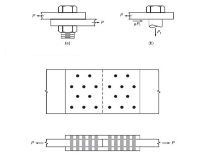
with two critical shear planes. Hence, each bolt has twice the shear capacity of a bolt in a lap joint. Figure shows a hanger connected by bolts to the bottom flange of a girder. Here the bolts are in tension. An example of a situation where bolts are subjected to combined shear and tension is shown in Fig. In this connection, all bolts are equally loaded in shear. However, because of the eccentricity of the applied load, the top row of bolts also resists tensile stress.
Example 1.
Bolts in Shear and Bearing with Deformation a Design Consideration The connection shown in Fig. consists of four, grade A490, ¾-in-diameter bolts. The bolts are snug-tight and threads are excluded from the shear planes. Deformation around the bolt holes is a design consideration and the bolt spacing is as indicated. The angles and gusset plate are fabricated from A36 steel. Assuming that the angles and gusset plate are satisfactory, determine the shear force that may be applied to the bolts in the connection. The bolt edge distance perpendicular to the direction of the tensile force is obtained from Fig.
L=1.75 in
The bolt edge distance in the direction of the tensile force is obtained from Fig. 10.7
Lc=2 in
Lc= clear distance, in the direction of force, between the edge of the hole and the edge of the 3/4-in gusset plate
= Lc - (d+1/16)/2
= 1.59 in
The bolt pitch is obtained from Fig. 10.7 as s = 3 in
4d
>3d +1/16 ... full bearing capacity possible on all bolts \
Hence, tear out does not govern and a nominal bearing stress of 2.4Fu is applicable. The available bearing capacity of the four bolts on the 3/4-in plate material is
LRFD | ASD
|
The design bearing strength is
| The allowable bearing strength is
|
The double shear capacity of the for, grade  in diameter bolts with threads excluded from the shear planes is
LRFD | ASD
|
The design shear strength is
| The allowable shear strength is
|
Structural fasteners are strong, heavy-duty fasteners that are vital for the development of structures which consist of metallic-to-metallic connections. ... To be taken into consideration for structural purposes, fasteners want to be fabricated from quenched and tempered metallic with a minimum tensile electricity of one hundred twenty ksi.
Structural fasteners are strong, heavy-duty fasteners that are vital for the construction of structures which consist of metallic-to-metallic connections. In other words, they're used whilst one metal structure needs to be related to another.
The regular application of structural fasteners is in bridge and building construction, where they're used to connect metal beams and girders. To be taken into consideration for structural purposes, fasteners want to be fabricated from quenched and tempered metallic with a minimum tensile electricity of one hundred twenty ksi.
Some of the maximum commonly used structural fasteners are:
The quality of structural fasteners specified is of top significance due to the fact they may be protecting collectively heavy and crucial structures. Therefore, they should be durable, sturdy, rust-evidence and corrosion-loose for numerous years. Using poor quality structural fasteners now no longer best reduces the durability of the overall structure but additionally puts lives at risk
Rivets
A rivet is a mechanical fastener for creating an everlasting be a part of among or more metal sheets. Riveting is the act of fastening or securing plates with one or more rivets. The rivet accommodates a shank with an undeniable stop (or tail), and a head on the opposite stop. The rivet has proved to be one of the maximum reliable and safe way of fastening, forming an everlasting and structurally sturdy be a part of.
The method of riveting (or creating a riveted joint) accommodates making an entire in say, metal plates, aligning the hole, then putting the rivet thru it with the undeniable stop projecting thru (‘A’ withinside the diagram). Hammering the projecting tail stop of the rivet reasons it to mushroom, increasing through round 1. five instances its unique diameter, inflicting a head to form (‘B’) which secures the rivet and the be a part of permanently. The very last form of the rivet is consequently much like a dumbbell, with the unique head referred to as the factory head and the brand-new tail stop referred to as the shop head (or greenback tail). The finished rivet can support shear and tension loads.

Bolts
The terms ‘bolts’ and ‘screws’ are occasionally used interchangeably, and the difference among them may be complex, however, in easy terms, a bolt passes thru the substances it is fixing collectively (typically right into a nut at the opposite side), while a screw threads without delay into them.
Bolts are frequently made of metallic, and in which resistance is needed to weather or corrosion, they'll be galvanised, or chrome steel, brass, zinc or titanium can be used.
Types of Bolts
There are many one-of-a-kind types of bolts which may be selected primarily based totally at the precise requirement or the substances involved. Some of the maximum not unusual place kinds include:
Anchor bolt
Usually embedded in concrete or masonry for structural applications.
Carriage bolt
Used to fasten steel to timber, with a squared undercut to the head which holds the bolt in place as soon as it has been tightened.
Elevator bolt
Commonly utilized in conveyor systems, an elevator bolt has a flat, undeniable or countersunk head which holds the bolt in place whilst tightened.
Flange bolt
Also referred to as frame bolts, this form of bolt distributes the bearing load the use of a washer at the undercut of the head.
Hanger bolt
This form of bolt contains threaded ends rather of getting a head, one in every of which contains a wood screw.
Hexagon bolt/Tap bolt
A hexagon bolt contains a head that has six sides, with threading that starts off evolved part-manner down the shank, while a tap bolt’s shank is threaded the complete length.
Huck bolt
A proprietary bolt wherein the pin and collar are swaged collectively the use of a specialist tool to shape a permanent fixing.
Lag bolt
Also referred to as lag screws, that is a heavy-duty fastener that creates its own mating thread in timber and different soft substances whilst tightened.
Machine bolt
This form of bolt has a brief shank and is supposed for assembling steel components thru predrilled holes.
Plow bolt
This form of bolt is generally used in production tools and different gadgets because of its durability, and is characterized by means of its flat countersunk head and rectangular shank neck.
Sex bolt
Rather than requiring a nut, the shank of sex bolts is blanketed with a ‘mating’ female component. These are beneficial for fastening components that cannot be exposed to abrasive threads.
Square head bolt
This is just like a machine bolt in that it has a brief shank, similarly to a 4-sided bolt head.
Stud bolt
This form of bolt has hexagon nuts on each end. Components are mounted among the 2 bolts.
Timber bolt
Bolts which are intended for use with large timber components.
T-head bolt
Has a T-shaped head which may be gripped by means of a wench and may in shape right into a slot with ease.
Toggle bolt
This form of bolt has an expanding wing-like nut which facilitates it to mount items to walls.
U-bolt
Similar to staples, U-bolts are bent withinside the shape of a ‘U’ and are in part threaded on each end.
Bolt Heads
Different kinds of head include:
Welds
Welding is a fabrication system wherein or extra elements are fused collectively by way of heat, pressure or each forming a be a part of because the elements cool. Welding is generally used on metals and thermoplastics however also can be used on wood. The finished welded joint can be called a weldment.
Some substances require the use of unique approaches and techniques. A quantity is considered unweldable, a time period now no longer generally determined in dictionaries however beneficial and descriptive in engineering.
The elements which are joined are referred to as a determine cloth. The cloth delivered to help shape the be a part of is known as filler or consumable. The shape of those substances might also additionally see them called determine plate or pipe, filler twine, consumable electrode (for arc welding), etc.
Consumables are generally chosen to be comparable in composition to the determine cloth, consequently forming a homogenous weld, however there are occasions, along with whilst welding brittle solid irons, whilst a filler with a completely one-of-a-kind composition and, therefore, residences is used. These welds are known as heterogeneous.
The finished welded joint might also additionally be called a weldment.
Types of Welding Joints
Gas Metal Arc Welding (GMAW/MIG)
This fashion of welding is likewise referred to as Metal Inert Gas (MIG). It makes use of a defensive fuel line alongside the twine electrode, which heats up the 2 metals to be joined. This technique calls for a constant voltage and direct-contemporary electricity source, and is the maximum not unusual place industrial welding system. It has 4 number one strategies of steel transfer: globular, brief-circuiting, spray and pulsed-spray.
Gas Tungsten Arc Gas Welding (GTAW/TIG)
Welding collectively thick sections of chrome steel or non-ferrous metals is the maximum not unusual place use for this technique. It is likewise an arc-welding system that makes use of a tungsten electrode to supply the weld. This system is plenty extra time eating than the opposite 3 and plenty extra complex.
Shielded Metal Arc Welding (SMAW)
With this precise form of welding, the welder follows a guide system of stick welding. The stick makes use of an electric contemporary to shape an arc among the stick and the metals to be joined. This is frequently used withinside the production of metallic systems and in industrial fabrication to weld iron and metallic.
Flux Cored Arc Welding (FCAW)
This becomes evolved as an opportunity to defend welding. The semi-computerized arc weld is frequently utilized in production projects, way to its excessive welding velocity and portability.
BOLTED SHEAR CONNECTIONS
- Shear failure of the bolts
- Failure of member being linked because of fracture or block shear or ….
- Edge tearing or fracture of the linked plate
- Tearing or fracture of the linked plate among bolt holes
- Excessive bearing deformation on the bolt hole
- Average shearing strain withinside the bolt =
fv = P/A = P/ (π db 2 /4)
- P is the weight appearing on an individual bolt - A is the place of the bolt and db is its diameter
- Strength of the bolt =
P = fv x (π db 2 /4)
in which fv = shear yield strain = 0.6Fy
- Bolts may be in unmarried shear or double shear as proven below.
- When the bolt is in double shear, cross-sections are powerful in resisting the weight. The bolt in double shear can have the two times the shear power of a bolt in unmarried shear.

Welded joints are extra rigid than bolted joints, due to the continuity of the pass section. On the opposite hand, bolted joints are related with plates or angles, and the deflection of those factors throughout load switch provides flexibility. For this reason, bolted joints permit extra motion with much less structural stress.
easy connections
These are nominally pinned connections that are assumed to transmit quit shear best and to have negligible resistance to rotation. Therefore, do now no longer switch big moments on the closing limit state. This definition underlies the layout of multi-story braced frames withinside the United Kingdom designed as easy construction, wherein the beams are designed as simply-supported and the columns are designed for axial load and the small moments prompted via way of means of the quit reactions from the beams. Stability is supplied to the body via way of means of bracing or via way of means of the concrete core.
Two precept types of easy connection (as proven on the right) are used withinside the UK, those being:
Commonly encountered easy connections include:
Simple connections also can be wanted for skewed joints, beams eccentric to columns and connection to column webs. These are classed as unique connections and are dealt with separately.
Moment resisting connections are used in multi-story un-braced buildings and in single-story portal body buildings. Connections in multi-story frames are maximum possibly to be bolted, complete intensity quit plate connections or prolonged quit plate connections. Where a deeper connection is needed to offer a bigger lever-arm for the bolts, a haunched connection may be used. However, as extra fabrication will result, this scenario ought to be averted if possible.
For portal body structures, haunched second resisting connections on the eaves and apex of a body are nearly always used, as similarly to presenting extended connection resistances, the haunch will increase the resistance of the rafter.
The maximum generally used second resisting connections are bolted quit plate beam-to-column connections; those are proven withinside the parent below.
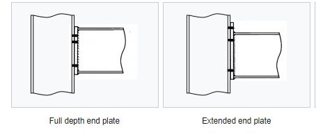
Instead of bolted beam-to-column connections, welded connections can be used. These connections can provide full moment continuity but are expensive to produce, especially on site. Welded beam-to-column connections can be prepared in the fabrication workshop with a bolted splice connection within the beam spam, at a position of lower bending moment. Welded connections are also used for the construction of buildings in seismic areas.
Other types of moment resisting connections include:
Bolted beam-to-column connections
Bolted end plate joints between I-section or H-section beams and columns as shown in the figure below are designed using the approach described in BS EN 1993-1-8[1]. Bolted end plate splices and apex connections, which use similar design procedures, are covered in the section on splices.

Typical bolted end plate beam-to-column connections
Design basis
The resistance of a bolted end plate connection is provided by a combination of tension forces in the bolts adjacent to one flange and compression forces in bearing at the other flange. Unless there is axial force in the beam, the total tension and compression forces are equal and opposite. Vertical shear is resisted by bolts in bearing and shear; the force is usually assumed to be resisted mainly by bolts adjacent to the compression flange. These forces are illustrated diagrammatically in the figure on the right.
At the ultimate limit state, the center of rotation is at, or near, the compression flange and, for simplicity in design, it may be assumed that the compression resistance is concentrated at the level of the center of the flange.
The bolt row furthest from the compression flange will tend to attract the greatest tension force and design practice in the past has been to assume a 'triangular' distribution of forces, pro rata to the distance from the bottom flange. However, where either the column flange or the end plate is sufficiently flexible (as defined by NA.2.7 of the UK NA [2]) that ductile behaviour is achieved, the full resistances of the lower rows may be used (this is sometimes referred to as a 'plastic distribution of bolt row forces').

Triangular distribution

‘Plastic’ distribution
Design method
The full design method for an endplate connection is necessarily an iterative procedure: a configuration of bolts and, if necessary, stiffeners are selected; the resistance of that configuration is evaluated; the configuration is then modified for greater resistance or greater economy, as appropriate; the revised configuration is re-evaluated, until a satisfactory solution is achieved.
STEP 1
Calculate the effective tension resistances of the bolt rows. This involves calculating the resistance of the bolts, the end plate, the column flange, the beam web and the column web. The effective resistance for any row may be that for the row in isolation, or as part of a group of rows, or may be limited by a 'triangular' distribution from compression flange level.
The conclusion of this stage is a set of tension resistances, one value for each bolt row, and the summation of all bolt rows to give the total resistance of the tension zone.
STEP 2
Calculate the resistances of the compression zone of the column web, taking account of the shear force in the column web, and of the beam flange.
STEP 3
Calculate the shear resistance of the column web.
STEP 4
If the total tension resistance exceeds the compression resistance, (Step 2) or column web shear resistance (Step 3), calculate reduced effective tension resistances for the bolt rows, where necessary to ensure equilibrium.
Calculate the moment resistance. This is the summation of the products of bolt row force multiplied by its respective lever arm, calculated from the center of compression.
STEP 5
Calculate the shear resistance of the bolt rows. The resistance is taken as the sum of the full shear resistance of the bottom row (or rows) of bolts (which are not assumed to resist tension) and 28% of the shear resistance of the bolts in the tension zone (assuming, conservatively, that they are fully utilized in tension).
STEP 6
Verify the adequacy of any stiffeners in the configuration.
STEP 7
Verify the adequacy of the welds in the connection. (Note that welds sizes are not critical in the preceding Steps).
Components in compression in direct bearing need only a nominal weld, unless moment reversal must be considered.
Verification of the resistance of a welded end plate connection in seven steps

The verification of the resistance of a welded end plate connection considering each of the components that make up the connection is illustrated in the figure right and accompanying table below.
Zone | Ref | Component | Procedure |
Tension | a | Bolt tension | Step 1a |
b | End plate bending | Step 1a | |
c | Column flange bending | Step 1a | |
d | Beam web tension | Step 1b | |
e | Column web tension | Step 1b | |
f | Flange to end plate weld | Step 7 | |
g | Web to end plate weld | Step 7 | |
Horizontal shear | h | Column web panel shear | Step 3 |
Compression | j | Beam flange compression | Step 2 |
k | Beam flange weld | Step 7 | |
I | Column web | Step 2 | |
Vertical shear | m | Web to end plate weld | Step 7 |
n | Bolt shear | Step 5 | |
p | Bolt bearing (plate or flange) | Step 5 | |
| |||
Methods of strengthening
Careful selection of the members during design will often avoid the need for strengthening of the joint, and will lead to a more cost-efficient structure. Sometimes, however, there is no alternative to strengthening one or more of the connection zones. The range of stiffeners which can be employed is shown in the figures below.
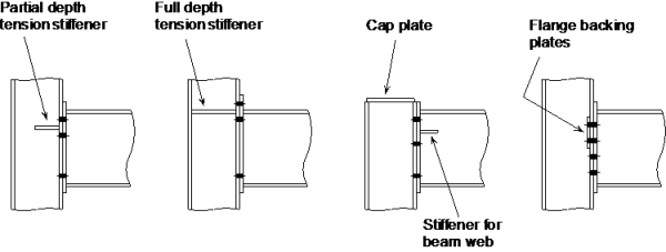


Methods of strengthening
The type of strengthening must be chosen such that it does not clash with other components at the connection. This is often a problem with conventional stiffeners when secondary beams connect into the column web.
There are usually several ways of strengthening each zone and many of them can contribute to overcoming a deficiency in more than one area, as shown in the table below.
Type of column stiffener | Deficiency | |||||||
Web in tension | Flange in bearing | Web in compression | Web in shear |
| ||||
| • | • | • |
|
| |||
• | • | • |
|
| ||||
Supplementary web plates | • |
| • | • |
| |||
Diagonal stiffeners (N & K) | • | • |
| • |
| |||
Morris stiffeners | • | • |
| • |
| |||
Flange backing plates |
| • |
|
|
| |||
Eccentric Connections
If the force applied does not passes through the CG of the joint then such joint carries moment in addition to an axial direct force. Such types of connections are called as eccentric connections.
Two common loading conditions are discussed in the next two sections, followed by a discussion of the generalized approach for distributing applied loads over a bolt pattern.
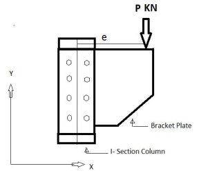
CONNECTIONS SUBJECTED TO ECCENTRIC SHEAR
Seat Connections
Framed Connections
Bracket Connections
Key Takeaways:
References:
1. McCormac, J.C., Nelson, J.K. Jr., Structural Steel Design. 3rd edition. Prentice Hall, N.J., 2003.
2. Galambos, T.V., Lin, F.J., Johnston, B.G., Basic Steel Design with LRFD, Prentice Hall, 1996
3. Segui, W. T., LRFD Steel Design, 2nd Ed., PWS Publishing, Boston.
4. Salmon, C.G. and Johnson, J.E., Steel Structures: Design and Behavior, 3rd Edition, Harper & Row, Publishers, New York, 1990.
5. Related Codes of Practice of BIS
6. NBC, National Building Code, BIS (2017).
7. ASCE, Minimum Design Loads for Buildings and Other Structures, ASCE 7-02, American Society of Civil Engineers, Virginia, 2002.
8. Subramanian, N. (2010). Steel Structures: Design and Practice, Oxford University Press.
9. Duggal, S.K. (2014). Limit State Design of Steel Structures, McGraw Hill.


