Unit – 4
Design for flexural and flexural-torsional buckling
Introduction
Definition 1: Flexural buckling
This kind of buckling can occur in any compression member that reviews a deflection as a result of bending or flexure. Flexural buckling takes place approximately the axis with the most important slenderness ratio, and the smallest radius of gyration.
Definition 2: Torsional buckling
This kind of buckling most effective takes place in compression individuals which might be doubly-symmetric and feature very narrow cross-sectional elements. It is as a result of a turning approximately the longitudinal axis. Torsional buckling takes place usually in built-up sections, and nearly by no means in rolled sections.
Definition 3: Flexural-torsional buckling
This kind of buckling most effective takes place in compression individuals which have unsymmetrical cross-segment with one axis of symmetry. Flexural-torsional buckling is the simultaneous bending and twisting of a member. This usually takes place in channels, structural tees, double-angle shapes, and equal-leg unmarried angles.
Design for flexural buckling: -
Flexural Limit States Increasing the loading at the beam will sooner or later reason failure of the beam via way of means of either
• Yielding of the fabric and formation of a plastic hinge and a collapse mechanism
• Lateral-torsional buckling of the beam.
• Local buckling of the flange or net of a beam that isn't always compact Adequate lateral bracing of a beam will make certain that complete plasticity is done previous to lateral-torsional buckling occurring.
Using a form this is compact will make certain that complete plasticity is done previous to flange or net neighborhood buckling.
Design Flexural Strength and Allowable Flexural Strength
After the nominal flexural strength is determined, the design flexural strength and the allowable flexural strength may be obtained from AISC 360, Sec. F1 as
ϕb Mn = design flexural strength
≥ Mu ... required flexural strength using LRFD load combinations
Mn /Ωb = allowable flexural strength
≥Ma ... required flexural strength using ASD load combinations.
where ϕb = resistance factor for flexure = 0.9
Ωb = safety factor for flexure = 1.67
American Institute of Steel Construction, Steel Construction Manual (AISC Manual)3 Table 3-2, for a value of Cb = 1.0, provides values of ϕb Mp and Mp /Ωb.
Example 4.1. Beam Selection Determine the lightest W10 section suitable for the beam shown in Fig. 4.4. The loading consists of a uniformly distributed dead load of wD = 1.0 kip/ft, which includes the weight of the beam, and a uniformly distributed live load of wL = 3.0 kips/ft. The beam is continuously braced on its compression flange and has a yield stress of Fy = 50 ksi.
Since the beam is continuously braced, lateral-torsional buckling does not occur. Hence, full plasticity of the section is possible and the nominal moment is
Mn = Mp
Applying American Society of Civil Engineers, Minimum Design Loads for Buildings and Other Structures (ASCE 7)4 Secs. 2.3 and 2.4 gives

LRFD | ASD |
From ASCE 7 Sec.2.3.2 combination 2:
From AISC Manual Table 3-2 for a value of
| From ASCE 7 Sec.2.3.2 combination 2:
From AISC Manual Table 3-2 for a value of
|
In addition to designing a beam for flexural capacity, the serviceability limit states must also be checked. These include deflection and vibration limitations.
Flexural-torsional buckling can be described as a combination of bending and twisting response of a member in compression. Such a deflection mode must be considered for design purposes. This mostly occurs in columns with "open" cross-sections and hence have a low torsional stiffness, such as channels, structural tees, double-angle shapes, and equal-leg single angles. Circular cross sections do not experience such a mode of buckling.
The idea of the powerful duration elements of columns has been properly set up and broadly utilized by training engineers and performs an important role in compression member layout. The most structural layout codes and specs have provisions regarding the powerful duration issue. The intention of this chapter is to gift a modern engineering exercise of the powerful duration factor for the layout of columns in structures. In the primary a part of this chapter, the primary idea of the powerful duration issue is discussed. And then, the layout implementation for remoted columns, framed columns, crossing bracing systems, latticed members, tapered columns, crane columns, in addition to columns in gable frames is presented. The dedication of whether or not a body is braced or unbraced is likewise addressed. Several particular examples are given to demonstrate the dedication of powerful duration elements for distinctive instances of engineering applications.
The powerful duration issue is received with the aid of using fixing the precise equations numerically which require many ordinary calculations or with the aid of using the usage of a couple of alignment charts for the 2 instances of braced frames and sway frames. The accuracy of these charts relies upon on the dimensions of the chart and the readers sharpness of vision.
Effective Length Calculations (Columns: IS 456)
Clear Height
The clean top is the clean size between the restraining beams at the lowest of the stack and the restraining beams at the pinnacle of the stack. The clean top can be distinctive in every direction.
If, at an give up of the stack, no powerful beams or flat slab to encompass are found, then the clean top consists of the stack past this restraint, and the equal policies follow for locating the give up of the clean top on the give up of the following stack (and so on).
Effective Length
The effective length, le is calculated automatically - you also have the ability to override the calculated value.
le=K * l where l=clear height between end restraints K=effective length factor |
The value of K may be obtained from the following equationsAA:
a) For non-sway (braced frames):
K= [(1 + 0.145*(β1 + β2) - 0.265*β1*β2] / (2 - 0.364*(β1 + β2) - 0.247*β1*β2]
b) Sway frames (Moment resisting frames):
K=MIN (1.2, {[1 - 0.2*(β1 + β2) - 0.12*β1*β2] / [1 - 0.8(β1 + β2) + 0.6 β1*β2]}0.5
where
β is the rotation release factor and has two values, β1 and β2 at the two ends (top and bottom of the columns respectively)
β1, β2=ƩKc/(ƩKc+ƩKb)
ƩKc=effective flexural stiffness of the columns
ƩKb=effective flexural stiffness of the beams
If Q≤0.04 If Q>0.04 where Q=Stability index |
The Effective Length Factor For the design of a column restrained by hypothetical end conditions (fixed, pinned, or free), an effective length factor table is provided in the AISC manual (Fig.2.3). Table C_A_7.1 Approximate Values of Effective Length Factor, K
The table in Fig. shows the theoretical K values and recommended design K values for the ideal condition depending on the end conditions. In the table, cases (a), (b), and (d) represent sidesway inhibited conditions. As shown in the table, the range of the K-factor appears between 0.5 and 1.0 for the theoretical K-values and between 0.65 and 1.0 for the recommended design K-values. For cases (c), (e), and (f), which represent the sidesway uninhibited condition, the range of K-values is above 1.0 for both the theoretical and the recommended design K-values.
| ||||||||||||||||||||||||||||
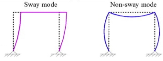
A frame is considered to be non-sway (braced) if it is sufficiently braced by lateral bracing elements like structural walls. On the other hand, frames that provide lateral resistance only through columns are considered to be sway frames (unbraced).
If the conditions mentioned above are not met, the frame is considered to be a sway (unbraced). The factors that make frame to sway laterally are:
Differences between sway (braced) and non-sway (unbraced) frames can be summarized in Table-1:
Table-1: Differences between Sway Frames and Non-sway Frames
Sway (braced) Frames | Non-sway (unbraced) Frames |
Sway frames do not have adequate stiffness against in-plane horizontal forces, hence, additional forces or moments arising from horizontal displacements should be accounted for in the analysis | Non-sway frame response to in-plane horizontal forces is sufficiently stiff to neglect any additional forces or moments arising from horizontal displacements |
The structure is symmetric, and loading is symmetric | Loading is asymmetric |
It has only a rotational degree of freedom, and translational degree of freedom does not exist | It has in-plane displacements due to asymmetrical loading, different length of supports, and/or different moment of inertia |
Joints change their positions due to deformation | Joints do not change their position due to deformation |
Second-order analysis should be used | First-order analysis should always be used for the analysis of non-sway frame |
For the purposes of analysis and design, steel frames have traditionally been regarded as belonging to one of two categories:
Of course, examples exist for which elements of both types are present; the present discussion does not consider these cases in developing the subject.
In Eurocode 3 this simple subdivision has been extended by including consideration of the method of analysis and including joints that behave as semi-rigid. This leads to the more complex classification system that is shown in Table 1.
Type of framing | Method of global analysis | Types of connections |
Simple | Pin joints | Nominally pinned Nominally pinned |
Continuous | Elastic | Rigid Nominally pinned |
Rigid-Plastic | Full-strength Nominally pinned | |
Elastic-Plastic | Full-strength - Rigid Nominally pinned | |
Semi-continuous | Elastic | Semi-rigid Rigid Nominally pinned |
Rigid-Plastic | Partial-strength Full-strength Nominally pinned | |
Elastic-Plastic | Partial-strength - Semi-rigid Partial-strength - Rigid Full-strength - Semi-rigid Full-strength - Rigid Nominally pinned |
Table: Methods of framing and global analysis in Eurocode 3
This introductory lecture does not cover the cases where the joints are semi-rigid. Further information on this type of joint and their influence on frame design is given.
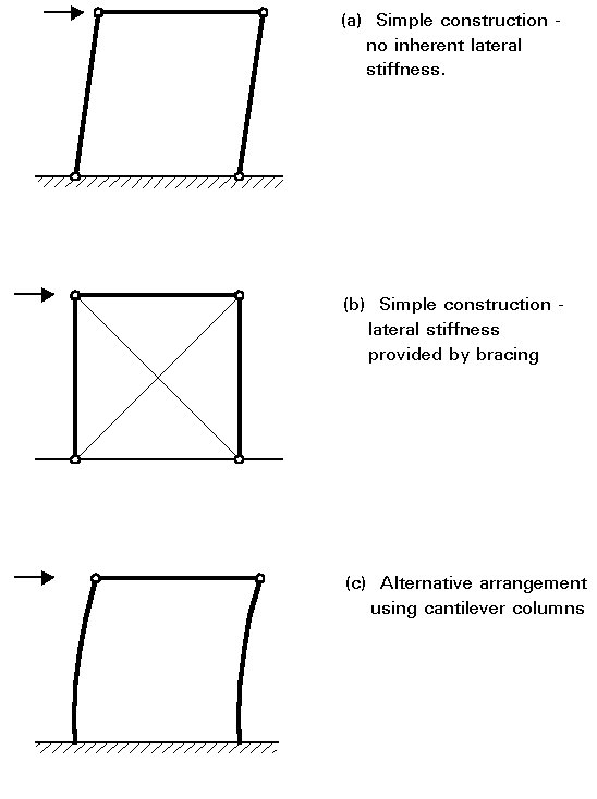
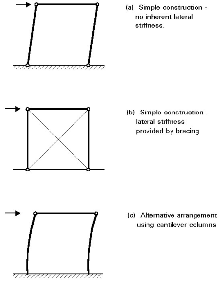
Building frames designed and executed according to this principle require comparatively little analysis as the loads may be allocated to individual members on the basis of simple statics. Since the joints are assumed to be incapable of transmitting moments, lateral stability requires the use of bracing because a rectangular bay with pinned beam to column connections, of course, possess no lateral stiffness. The only exception to this condition is when the feet of the columns are rigidly fixed to a solid foundation so that they can function as vertical cantilevers. Figure 2 illustrates these points.
Once the forces in the members have been decided upon, design may be conducted by considering individual beams, columns and joints, using the procedures presented. All horizontal loading is assumed to be resisted by the bracing system and, in the terminology of Eurocode 3 [1], the structure is designed as a braced frame.
When rigid joints are used, considerable interaction between beams and columns occurs due to transfer of moments around the frame. Various approaches to analysis and design may be employed; the most important consideration is the extent to which the effects of deflections on the response of the frame must be taken into account. Although rigid joints may be used in conjunction with bracing, construction economies make this arrangement an uncommon solution. Rigid joints are normally only used as an alternative to bracing so that lateral stiffness is provided by so-called frame action as illustrated in Figure 3.
METHODS OF ANALYSIS
In first-order elastic analysis a linear relationship between the applied loading F and the deformations () is assumed. The internal force distribution in the frame is assumed to be unaffected by the displacements in the frame.
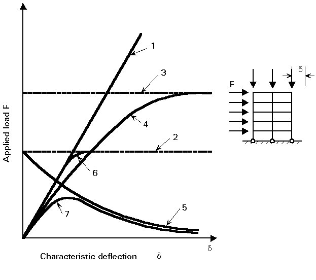
Frame analysis can therefore be conducted according to linear elastic principles as outlined in Lecture 7.1. The frame responds according to line 1 in Figure.
First-Order Rigid-Plastic Analysis
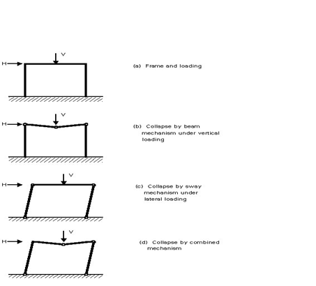
Rigid-plastic analysis (or the application of simple plastic theory) neglects the effects of elastic deflections and assumes that all structural deformation takes place in discrete regions, called plastic hinges, where plasticity has developed. When using first-order, rigid-plastic theory only the collapse condition is addressed. This condition occurs when sufficient plastic hinges are assumed to have formed to convert the structure into a mechanism. Thus, the path by which this stage is reached, i.e., the sequence of formation of the hinges and any intermediate distributions of internal forces, are not considered. Figure 5 illustrates the concept for 3 cases of vertical, horizontal and combined loading, whilst curve 2 in Figure 4 gives the frame response according to this approach. Due to the form of the analysis, no information is provided on the magnitude of the deflections. The analysis gives only that all stiffness is lost at the collapse load and deflections therefore (in theory) become uncontrolled.
Elastic Critical Load
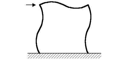
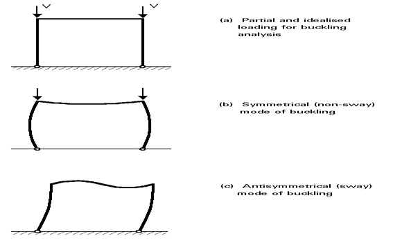
Using the methods described, it is possible to calculate the buckling loads for frames under suitably idealized loading. Depending upon the content and complexity of the frame, several different buckling modes, each with its associated elastic vertical load, may be possible. For the simple portal frame shown in Figure 6, both a symmetrical and an anti symmetrical mode are possible; the latter will usually be avoided with a much lower critical load. Once again, the analysis provides no information on the magnitude of the deflections; it simply identifies a particular load level. The curve 3 in Figure 4 gives the representation of the critical load obtained by an elastic buckling analysis.
In second-order elastic analysis the effect of elastic deformations on the internal force distribution is taken into account. The result is a transition from the linear analysis line 1 at low loads to the elastic critical line 3 at large deflections. For frames the second-order effects may be separated into 2 parts:
Second-Order Rigid-Plastic Analysis
If the deformations that may develop as a result of the formation of the plastic collapse mechanism are allowed for when formulating the equilibrium of the frame, then the result is the developing mechanism curve of line 5 in Figure 4. This curve shows that equilibrium can only be maintained with a reduction in the level of the applied loads.
First-Order, Elastic-Plastic Theory
If a linear elastic analysis is modified to allow for reductions in frame stiffness with the progressive formation of plastic hinges at increasing levels of the applied load, then the response curve of line 6 is obtained. This line exhibits progressive loss of stiffness as each plastic hinge is formed and eventually merges with the rigid-plastic line 2.
Second-Order, Elastic-Plastic Analysis
When the analysis that traces the formation of plastic hinges also allows for the effects of deformations in setting up the governing equations, then line 6 is modified somewhat into line 7. Line 7 initially follows the first-order elastic line 1 but diverges from this line to follow the second-order elastic line 4 as destabilising effects become more significant. Formation of the first plastic hinge - which occurs at a slightly lower applied load than is the case with the first-order, elasto-plastic analysis due to the larger deformation associated with second-order analysis - further reduces the stiffness, causing line 7 to diverge from line 4. This divergence becomes more pronounced as more plastic hinges form. The peak of this curve corresponds to the failure load predicted by this type of analysis. At large deformations line 7 tends to merge with the curve for the mechanism, line 5.
Second-Order, Plastic Zone Analysis
If the spread of plasticity both through the cross-section and along the member length is taken into account, instead of assuming that it is concentrated into the desirable regions of the plastic hinges, then the resulting type of analysis is usually termed plastic zone theory. It provides an even closer representation of actual behaviour and leads to a curve similar to line 7.
Classification as Sway or Non-Sway
A frame is classified as non-sway for a given load case if the following criterion is satisfied:

where
Vsd is the design value of the total vertical load
Vcr is the elastic critical load for failure of the frame in a sway mode.
For multi-story beam-and-column plane frames, with beams connecting each column at each story level, classification as non-sway can be made for a given load combination, simply by determining whether the following condition is satisfied:

where
is the deflection over a story height (inter story drift)
h is the story height
V is the vertical reaction at the bottom of a storey
H is the horizontal reaction at the bottom of a storey.
Frames classified as sway must subsequently be checked for overall sway stability using the procedures given in Eurocode 3 [1].
The modelling of structural systems will be covered in Annex H in a future addendum to Eurocode 3 [2]. In the meantime, the following general principles apply.
It is conventional to assume that the members in a principle structural frame have center lines intersecting at a point. The manner in which the design actions are distributed around the frame is dependant on the nature of the connections and the measures employed to resist lateral loading. Table 3, extracted from Eurocode 3, illustrates the different methods of global analysis which are permitted depending on the type of framing and connection.
The method for analysis and design of simple framing is dealt with at length The frame incorporates a separate bracing system which is designed to resist lateral loading and provide lateral stability to the part of the structure resisting gravity load (see Figure 9).
The model assumes the following:
As a result, the structure is statically determinate. The internal forces and moments are therefore determined from a consideration of statics.
Simple frames are invariably designed as non-sway (see Section 5) and, as a result, the effect of frame deformations on the distribution of internal forces and moments can be ignored.
Such structures are statically indeterminate. A detailed appraisal of the analysis and design of partial-strength (or partially continuous) frames is presented, whilst those where full continuity is assumed at the connection are addressed.
For continuous frames, the internal forces can be determined using either:
a. elastic global analysis.
b. plastic global analysis.
Whilst elastic methods of global analysis can be used throughout, plastic global analysis is only applicable where the frame members are of the appropriate classification to enable the development of plastic hinges.
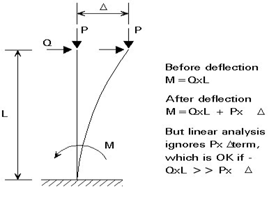
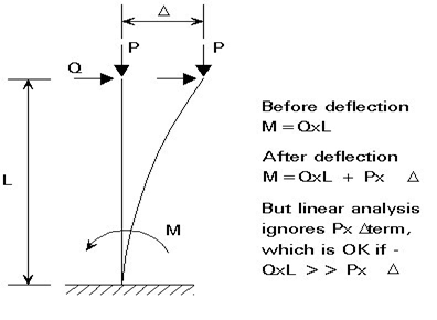
In a first-order analysis, the additional secondary actions due to the deformation of the structure (see Figure 10) are ignored.
This assumption is only valid in the following cases:
a. Where the frame is classified as braced (see Section 5.1).
b. Where the frame is classified as non-sway (see Section 5.2).
c. Where a design method is used in which an indirect allowance (amplification) is made for the occurrence of second-order effects.
In this latter case, the sway moments obtained from a first order linear elastic analysis are multiplied by the ratio:
(Formula 1) 1/ [1 - Vsd/Vcr], for Vsd/Vcr 0,25
where
Vsd is the design value of the total vertical load.
Vcr is the elastic critical value in a sway mode.
For conventional framed structures, the ratio Vsd/Vcr can be determined as follows:

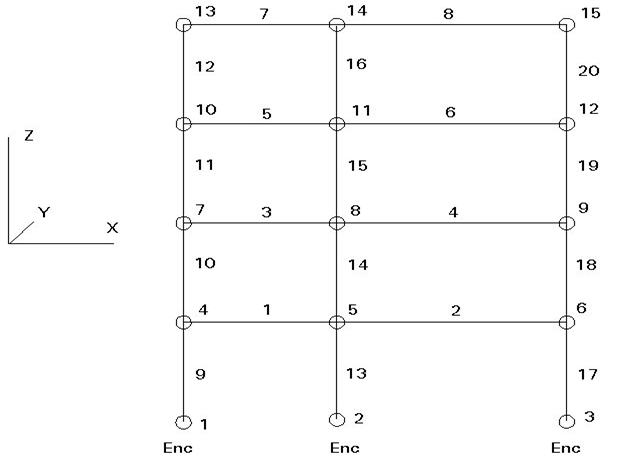
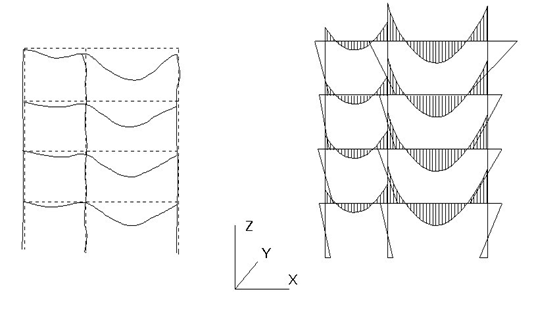
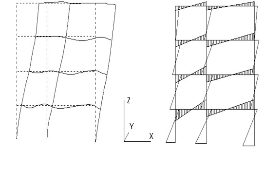
The first order elastic method of analysis is a convenient approach. Most design offices possess computer software capable of performing this method of analysis on large highly indeterminate structures. Figures 11 - 13 show typical graphical output from first order analysis made using computer software.
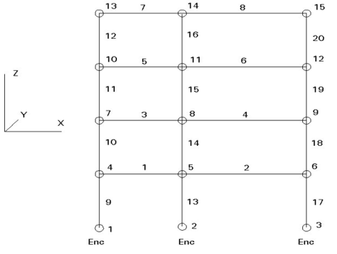

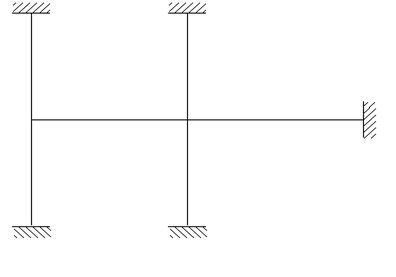
As an alternative, hand calculations can be performed on appropriate subframes within the structure (see Figure 14) comprising a significantly reduced number of members. These simple calculations are also recommended to make some physical check of the out-put of the computer.
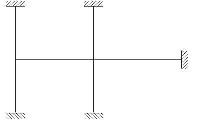
When conducting the analysis of an isolated subframe it is important that:
a. The subframe is indeed representative of the structure as a whole.
b. The selected boundary conditions are appropriate.
c. Account is taken of the possible adverse effects between adjacent subframes.
Plastic global analysis may be made by means of either:
Elastic-plastic methods require quite sophisticated computer programs, which enable second order effects to be taken into account.
As a design tool, Eurocode 3 [1] does present a method of rigid plastic analysis which takes into account secondary effects by amplifying the design internal forces and moments by means of the ratio given in Formula (1). The method is only applicable where frames have fixed bases and the only hinge to form in the column is at the base (see Figure 15) and the VSd/Vcr ratio does not exceed 0,2.
By means of this method the design is based on an incomplete mechanism in which the columns are designed to remain elastic at the calculated plastic hinge moment.
For building structures in which the required rotations are not calculated, all members containing plastic hinges shall have Class 1 cross-sections at the plastic hinge location.
Buckling is not to be viewed only as failure of the entire member " Especially in elements that carry such specific geometric forms that the parts can fail, e.g., W shapes, leading to failure of the ensemble, it is necessary to view the parts as well.
AISC Section B4 addresses the issue of local buckling " That is the failure of the “plate” parts of the form: Local buckling of Web! Local buckling of Flange " The strength equations in Chapter E are based on the assumption that the element will fail as a whole. This should be examined after it has been determined that local buckling did not occur.
It should be noted that “plate” elements (that have open surfaces that do not brace among themselves, e.g., W shapes, angles, etc.) are more susceptible to local buckling. " Compare factors used for plate elements vs closed elements such as rectangular or circular sections.
Lacing is generally preferred in case of eccentric loads. Battening is normally used for axially loaded columns and in sections where the components are not far apart. Flat bars are generally used for lacing. Angles, channels and tubular sections are also used for lacing of very heavily columns
To carry heavy loads a built-up column also called an open web column is provided. Such a column may consist of different components like, two channels, four angles, two I-sections etc. If an arrangement to connect or stitch together the individual components of such a column is not made then each component will act as a separate or independent unit.
In such case the design strength of the column will be the sum of the design strengths of the individual components which will definitely be much less than the design strength of the composite unit acting as a single unit. By providing an arrangement to connect the individual components, full use of the strength of the material is utilized.
Connecting the individual components assists in holding the components in their respective positions. The components of a built- up column can be connected by- (i) lacing and (ii) battening and accordingly such columns are called laced columns and battened columns respectively.
Laced Columns:
In this case the components of the composite section are connected by lacing. Lacing consists of connecting the components of the column by a system of generally flat plates. (In some cases, angles and channels are also used as lacings). Lacing plates may be 50 mm to 75 mm wide and 8 mm to 10 mm thick.
General Requirements for Lacing (IS 800):
(i) Compression members comprising two main components laced and tied, should where practicable have a radius of gyration about the axis perpendicular to the plane of lacing not less than the radius of gyration about the axis parallel to the plane of lacing.
(ii) As far as possible the lacing system shall be uniform throughout the length of the column.
(iii) Single laced systems on opposite faces of the components being laced together shall preferably be in the same direction so that one is the shadow of the other instead of being mutually opposed in direction.
(iv) The effective slenderness ratio (KL/r) e of laced columns shall be taken as 1.05 times the (KL/r) o, the actual maximum slenderness ratio, in order to account for shear deformation effects.
(v) Width of lacing bars – In bolted/riveted construction, the minimum width of lacing bars shall be three times the nominal diameter of the end bolt/rivet.
(vi) Thickness of lacing bars – The thickness of flat lacing bars shall not be less than one-fortieth of its effective length for single lacing and one-sixtieth of the effective length for double lacings.
(vii) Rolled sections or tubes of equivalent strength may be permitted instead of flats for lacings.
(viii) Angles of inclination – Lacing bars, whether in double or single or double system shall be inclined at an angle not less than 40° nor more than 70° to the axis of the built-up member.
(ix) Spacing – The maximum spacing of lacing bars, whether connected by bolting, riveting or welding, shall also be such that the maximum slenderness ratio of the components of the main member (a1/r1) between consecutive lacing connections is not greater than 50 or 0.7 times the most unfavourable slenderness ratio of the member as a whole, whichever is less, where a1 is the unsupported length of the individual member between lacing points, and r1 is the minimum radius of gyration of the individual member being laced together.
Design of Lacings:
The lacing shall be proportioned to resist a total transverse shear Vt, at any point in the member, equal to at least 2.5 per cent of the axial force in the member and shall be divided equally among all transverse lacing systems in parallel planes.
Battened Columns:
Compression members composed of two main components battened should preferably have the individual members of the same cross-section and symmetrically disposed about their major axis. Where practicable, the compression members should have a radius of gyration about the axis perpendicular to the plane of the batten not less than the radius of gyration about the axis parallel to the plane of the batten.
The battens should be placed opposite to each end of the member and at points where the member is stayed in its length and as far as practicable, be spaced and proportioned uniformly throughout. The number of battens shall be such that the member is divided into not less than three bays within its actual length from center to center of end connections.
The effective slenderness ratio (KL/r) c of battened columns, shall be taken as 1.1-time (KL/r) o, the maximum actual slenderness ratio of the column, to account for shear deformation effects.
Design of Battens:
Battens shall be designed to carry the bending moments and shear forces arising from transverse shear force Vt equal to 2.5 per cent of the total axial force in the whole compression member, at any point in the length of the member divided equally between parallel planes of the battens. Battened member divided equally between parallel planes of the battens.
Battened member carrying calculated bending moment due to eccentricity of axial loading, calculated end moments or lateral loads parallel to the plane of battens, shall be designed to carry actual shear in addition to the above shear. The main members shall also be checked for the same shear force and bending moments as for the battens.
Battens shall be of plates, angles, channels or I-sections and at their ends shall be riveted, bolted or welded to the main components so as to resist simultaneously a shear Vb = (V1C)/N5 along the column axis and a moment M = (V1C)/2N at each connection.
where,
V1 = Transverse shear force as defined above
C = Distance between center to center of battens, longitudinally
N = Number of parallel planes of battens, and
S = Minimum transverse distance between the centroid of the rivet/bolt group/welding connecting the batten to the main member.
Tie Plates:
Tie plates are members provided at the end of battened and laced members, and shall be designed by the same method as battens. In no case shall a tie plate and its fastening be incapable of carrying the forces for which the lacing or batten has been designed.
Size:
When plates are used for battens, the end battens and those at points where the member is stayed in its length shall have an effective depth, longitudinally, not less than the perpendicular distance between the centroids of the main members.
The intermediate battens shall have an effective depth of not less than three quarters of this distance, but in no case shall the effective depth of any batten be less than twice the width of one member in the plane of the battens.
The effective depth of a batten shall be taken as the longitudinal distance between outermost bolts, rivets or welds at the ends. The thickness of batten or the tie plates shall be not less than one-fiftieth of the distance between the innermost connecting lines of rivets, bolts or welds, perpendicular to the main member.
The requirement of bolt size and thickness of batten specified above does not apply when angles, channels or I-sections are used for battens with their legs or flanges perpendicular to the main member. However, it should be ensured that the ends of the compression members are tied to achieve rigidity.
Spacing of Battens:
In battened compression members where the individual members are not specifically checked for shear stress and bending moments, the spacing of battens, center to center of its end fastenings shall be such that the slenderness ratio (KL/r) of any component over that distance shall be neither greater than 50 nor greater than 0.7 times the slenderness ratio of the member as a whole about its Z-Z (axis parallel to the battens).
Laterally supported and un supported beams Generally, a beam resists transverse loads by bending action. In a typical building frame, main beams are employed to span between adjacent columns; secondary beams when used – transmit the floor loading on to the main beams. In general, it is necessary to consider only the bending effects in such cases, any torsional loading effects being relatively insignificant. The main forms of response to uni-axial bending of beams are listed in Table 1. Under increasing transverse loads, beams of category 1 [Table1] would attain their full plastic moment capacity. This type of behaviour has been covered in an earlier chapter. Two important assumptions have been made therein to achieve this ideal beam behaviour. They are:
The compression flange of the beam is restrained from moving laterally, and
Any form of local buckling is prevented. If the laterally unrestrained length of the compression flange of the beam is relatively long as in category 2 of Table 1, then a phenomenon, known as lateral buckling or lateral torsional buckling of the beam may take place. The beam would fail well before it could attain its full moment capacity.
This phenomenon has a close similarity to the Euler buckling of columns, triggering collapse before attaining its squash load (full compressive yield load). Lateral buckling of beams has to be accounted for at all stages of construction, to eliminate the possibility of premature collapse of the structure or component.
For example, in the construction of steel-concrete composite buildings, steel beams are designed to attain their full moment capacity based on the assumption that the flooring would provide the necessary lateral restraint to the beams. However, during the erection stage of the structure, beams may not receive as much lateral support from the floors as they get after the concrete hardens.
Hence, at this stage, they are prone to lateral buckling, which has to be consciously prevented. Beams of category 3 and 4 given in Table 1 fail by local buckling, which should be prevented by adequate design measures, in order to achieve their capacities. The method of accounting for the effects of local buckling on bending strength is available in IS: 800.
The conceptual behaviour of laterally unrestrained beams is described in detail in code. Various factors that influence the lateral buckling behaviour of a beam are explained. The design procedure for laterally unrestrained beams is also included. Section classification, Design moment capacity, Section modulus (elastic and plastic), shear design provisions, imperfection factors, web buckling, web crippling, deflection, requirements, etc.: Refer IS 800.
A structural member sub to transversed load is called as beam
Type of section for beam
1.most preferable section I section (ISWB ISMB) ISMB)
Classification of cls
[based on section modules ZP & Ze]
Laterally restrain beam
A beam in which compression flange is restrain laterally is called laterally restrain beam
<1.5×Ze×fyγ mo<1.5×Ze×fyγ mo for cantilever beam,
ii) if V>0.6×vd>0.6×vd Then IS pg 7009.22
md =mdv
where mdv=design bending strength under high shear
a) mdv=md-B(md-mfd) <1.2∗Ze∗fyγmo<1.2∗Ze∗fyγmo for plastic & compact section
b) mdv =Ze∗fyγmoZe∗fyγmo for semi compart section
md >> m
mfg=Zfd∗fyγmoZfd∗fyγmo
Zfd=zp-Aw∗D4Aw∗D4
4
1) Web buckling IS pg 67 IS pg 78 mole
2) Web cripling
3) Deflection
rippling
fwc=[(b1+b2) ∗tw] ∗fywγmo[(b1+b2) ∗tw] ∗fywγmo
buckling
b1b1=75 to 100mm
n1n1=D/2
n_22=2.5(tf+r1r1]
Deflection
sactual << ∫∫ limit-permisible
where
1) ∫act=wl348EI∫act=wl348EI (simply supported point load)
2) ∫act=5wl4384EI∫act=5wl4384EI (9.5 subjected to udl)
w= working load
E= 2×10⁵N/mm2×105N/mm2
I=mI about xx axis
Factors affecting lateral stability
The elastic critical moment, Mcr, as obtained in the previous Section, is applicable only to a beam of I section which is simply supported and subjected to end moments. This case is considered as the basic case for future discussion. In practical situations, support conditions, beam cross section, loading etc. vary from the basic case. Refer IS code for details.
Design requirements
1. Maximum bending stress, fb must not exceed allowable stress, Fb.
2. Deflection should not exceed allowable limit.
3. Maximum shear stress, fv shall not exceed allowable shear stress.
Design procedure:
1. Calculate design load.
2. Calculate design moment, M and bending stress, fb.
3. Select a trial beam size and calculate allowable bending stress, Fb (see problems)
4. Calculate deflection and check with allowable deflection ratio.
5. Calculate design shear and shear stress, fv.
6. Calculate allowable shear stress, Fv.
Limit state design - Design of laterally supported beams
1. Calculate the factored load and the maximum bending moment and shear force
2. Obtain the plastic section modulus required
Zp = (M*Vmo /Fy)
a suitable section for the beam-ISLB, ISMB, ISWB or suitable built-up sections (doubly symmetric only). (Doubly symmetric, singly symmetric and asymmetric- procedures are different)
3. Check for section classification such as plastic, compact, semi-compact or slender. Most of the sections are either plastic or compact. Flange and web criteria.

4. Calculate the design shear for the web and is given by

5. Calculate the design bending moment or moment resisted by the section (for plastic and compact)

6. Check for buckling
7. Check for crippling or bearing
8. Check for deflection
Design of laterally un-supported beams
1. Calculate the factored load and the maximum bending moment and shear force
2. Design of LSB is by trial-and-error method. The design bending stress is significantly less which is to be assumed to start with. Assume slenderness ratio and h/tf and get the corresponding critical bending stress and hence the corresponding design bending stress.
3. Determine the required plastic section modulus and select the section.
4. Determine the actual design bending stress of this selected section knowing its slenderness ratio which should be greater than that assumed previously. Otherwise revise the section.
5. Check for shear, buckling, crippling and deflection should be done Design bending strength can be calculated as per IS: 800
Design bending strength can be calculated as per IS: 800


 rolled or welded sections
 can b Elastic lateral buckling,
Torsional constant, 
Warping constant, 
Analysis of section:
To find the design moment of the section.
Laterally supported beam
Determine the moment of resistance of the beam from its plastic section modulus.
Knowing the type of beam and its span, the ultimate load can be determined.
Find the safe load using suitable partial safety factor for the loads.
Laterally supported beam for the given beam determines the design moment or MOR as follows.
First find the critical moment of the section knowing its properties.
Calculate the non-dimensional factors and hence fbd.
From this Md can be found. Problem can also be solved by using tables of IS code.
Key Takeaways:
References:
1. McCormac, J.C., Nelson, J.K. Jr., Structural Steel Design. 3rd edition. Prentice Hall, N.J., 2003.
2. Galambos, T.V., Lin, F.J., Johnston, B.G., Basic Steel Design with LRFD, Prentice Hall, 1996
3. Segui, W. T., LRFD Steel Design, 2nd Ed., PWS Publishing, Boston.
4. Salmon, C.G. and Johnson, J.E., Steel Structures: Design and Behavior, 3rd Edition, Harper & Row, Publishers, New York, 1990.
5. Related Codes of Practice of BIS
6. NBC, National Building Code, BIS (2017).
7. ASCE, Minimum Design Loads for Buildings and Other Structures, ASCE 7-02, American Society of Civil Engineers, Virginia, 2002.
8. Subramanian, N. (2010). Steel Structures: Design and Practice, Oxford University Press.
9. Duggal, S.K. (2014). Limit State Design of Steel Structures, McGraw Hill.


