Unit – 6
Beam-Columns
Introduction
The beam is a structural detail that stands in opposition to the bending. Mainly beam incorporates vertical gravitational forces, however additionally pull the horizontal hundreds on it.
The beam is referred to as a wall plate or sill plate that incorporates the transmits and cargo it to the girders, columns, or walls. It is connected with.
In the early centuries, timbers have been the maximum desired fabric for use as a beam for this structural help purpose, now to undergo the pressure together with carrying vertical gravitational pressure, now they're made from aluminum, steel, or different such materials.
In real means, beams are those structural materials, which undergo the sheer pressure of the weight and the bending moment.
To keep on the greater anxiety and cargo, pre-stressed concrete beams are broadly used in recent times in the foundation of bridges and different such humongous structures.
Types of Beams
A compression member, i.e., column, is a critical detail of each reinforced concrete shape. These are used to switch a load of superstructure to the inspiration safely.
Mainly columns, struts, and pedestals are used as compression individuals in buildings, bridges, supporting structures of tanks, factories, and plenty of greater such structures.
A column is described as a vertical compression member who's especially subjected to the powerful duration and axial hundreds of which exceeds 3 instances its least lateral size.
The compression member whose powerful duration is much less than 3 instances its least lateral size is referred to as Pedestal
Column
The compression member who's willing or horizontal and is subjected to axial hundreds is referred to as Strut. Struts are utilized in trusses.
The characteristic of columns is to switch the weight of the shape vertically downwards to switch it to a foundation.
Apart from the wall plays the subsequent features additionally:
Types of Columns
Difference Between Beam and Column
Minimum width of the beam is 200 mm. Minimum width of a column is 200 mm, however, for earthquake resistance, it should be 300mm.
Sr.No. | Beam | Column |
1 | Communally a horizontal member of a structure that resists transverse load is called a beam. | Communally a vertical member of a structure that resists axial/eccentric load is called a column. |
2 | The beam is carried load perpendicular to the longitudinal axis. | The column is carried load parallel to the longitudinal axis. |
3 | Beam is basically carried or resists bending and shear force. | Column is basically carried or resists compression load. |
4 | Beam’s shape can be square, rectangular, T shape, I shape, H shape. | Column shape can be rectangular, circular, square, T shape, L shape, C shape, elliptical etc. |
5 | Minimum width of the beam is 200 mm. | Minimum width of a column is 200 mm, however, for earthquake resistance, it should be 300mm. |
6 | Longitudinal steel in Beam is on two faces which are used to resist bending moment while the vertical loads are resisted by stirrups or inclined beam | Longitudinal steel in Column is on all faces which basically resists compression |
7 | Communally cast with slab and hence greater care is observed for its concreting and curing in case of RCC structures. | Communally cast in small batches and hence the quality of concreting as well as curing ignored in case of RCC structures. |
8 | Beam without building possible | Here, Column important part of building |
The flexural behaviour of symmetrically strengthened concrete (RC) columns forged of normal- and high-power concrete below each monotonic and cyclic loading is studied primarily based totally on an analytical procedure, which employs the real stress-pressure curves and takes into account the stress-route dependence of concrete and metal reinforcement. The evaluation is mainly prolonged into the post-height level with huge inelastic deformation at numerous implemented axial load level.
Types of forces
The forces that are generated are typically three-dimensional with components directed along one or more of the clinical co-ordinate axes. The effect of this is to resolve the force into a combination of components in any given plane, with the same magnitude of force having a different effect on the bone–implant interface depending on the direction in which it is applied. The main types of loading on the implant assembly that need to be considered are axial (compression/tension) forces and bending moments (Rangert et al. 1989; Quirynen et al. 1992).
Bending momentsIn both multiple- and single-unit restorations, bite forces create components of vertical loads and also transversal forces that give rise to bending moments on the crown–abutment–implant complex. Specific transverse bending loads can also be caused by premature contacts, bruxism or significantly angled implants (Misch 1999a). Bending movements can create high stress levels in implant components causing fatigue or component fracture. Adverse reactions at crestal bone levels surrounding the implant (Brunski 1988; Rieger et al. 1990a) can be caused by bending moments due to the higher concentration of stress gradients at the bone–implant interface (Fig. 14.7) when compared with true vertical loads (Rangert et al. 1989). High bending moments can exceed the mechanical load limits of the implants and are therefore more significant than axial forces (Glantz et al. 1993).
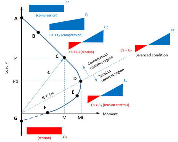
A load-moment interaction diagram planned on the P-M interaction chart represents the specific axial load capacity and ultimate bending moment capacity of a given section of column. The uniaxial bending moment capacity and axial load can be computed by using the principal of static symmetry and strain compatibility.
P-M INTERACTION CURVES FOR PRESTRESSED CONCRETE COLUMN
A load-moment interaction diagram planned on the P-M interaction chart represents the specific axial load capacity and ultimate bending moment capacity of a given section of column. The uniaxial bending moment capacity and axial load can be computed by using the principal of static symmetry and strain compatibility.
The impact of the concrete to the column strength is seen as a continuous curve, and the contribution of the steel bar (prestressing steel) and the structural steel in both faces as a curve with two lines comparatively straight which inter connect each other at a point. In that case of column with a high steel ratio, the shape of the interaction diagram become more linear and in case of low steel ratio, the interaction diagram is more curved. Strength is conventionally represented by plot of axial load capacity Pu versus the moment on the section at ultimate. Any combination of axial force and bending moment applied to the column cross section that falls inside the interaction curve is safe and be carried out by cross section. while any point outside curve represents a combination of axial force in moment that exceeds the strength of cross section. Point A on the vertical axis represents the axial compression. Point B represents zero tension point at face i.e., the combination of axial force Pu and moment Mu, when combined with prestrains caused by prestress which produces zero strain in the extreme concrete fiber. Point C is known as the balanced failure point. So, the position of neutral axis lies inside the cross section. Point D is the pure bending point where the axial force is zero.
Vertical members that are part of a building frame are subjected to combined axial loads and bending moments. These forces develop due to external loads, such as dead, live, and wind loads. Simply put, an interaction diagram (or curve) displays the combinations of the acceptable moment and axial capacities of a structural member.
The equivalency between an eccentrically applied load and an axial load–moment combination is shown below. Assume that a force P is applied to a cross-section at a distance e (eccentricity) from the centroid. Eccentric force P may now be combined with the force P acting downward at the centroid and a couple of Pe, which is a pure moment.
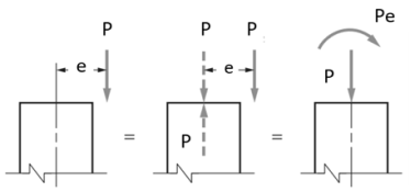
Different position of axial force from the section centroid produces various behaviors of a column as well as stress distribution in sections. These are plotted on the M-N Interaction Curve:
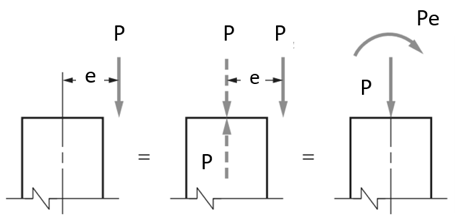
Example of an Interaction Diagram
Interpreting the Interaction Curve
For the design of a column to be considered adequate (safe), the combination of action effects (M, P) must be less than the combination of design strengths (M, P) from the interaction curve. This means that if the position of the M, P point on the plot is outside of the curve it is deemed as not meeting this criterion and considered unsafe.
The impact of axial load on their complete flexural behaviour is then diagnosed primarily based totally at the effects obtained. The axial load is discovered to have pretty huge impact at the flexural behaviour of RC columns below each monotonic and cyclic loading. Such results are discussed via exam of numerous factors together with the second-curvature relationship, second capacity, flexural ductility, version of impartial axis intensity and metal stress.
Moment amplification
In structural engineering the amplification factor is the ratio of 2nd order to first order deflections.
The amplification factor, additionally called gain, is the volume to which an analog amplifier boosts the power of a signal.
In the layout of slim metal beam-columns, the moment amplification factor is used to estimate the most bending moment. In the parametric study, significance of the preliminary deflection, the axial load ratio, the slenderness ratio and the end moment ratio are decided on because the parameters.
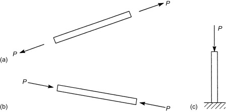
Axial loads are implemented alongside the longitudinal or centroidal axis of a structural member. If the movement of the weight is to growth the duration of the member, the member is stated to be in anxiety (Fig. 3.1(a)) and the implemented load is tensile. A load that has a tendency to shorten a member location the member in compression and is called a compressive load (Fig. 3.1(b)). Members such as the ones proven in Fig. 3.1(a) and (b) are generally discovered in pin-jointed frameworks in which a member in anxiety is referred to as a tie and one in compression a strut or column. More frequently, however, the name ‘column’ is related to a vertical member wearing a compressive load, as illustrated in Fig. 3.1(c).
There are 3 methods a compression member can buckle, or come to be unstable. These are flexural buckling, torsional buckling, and flexural-torsional buckling.
Flexural buckling
This form of buckling can arise in any compression member that reports a deflection due to bending or flexure. Flexural buckling happens approximately the axis with the most important slenderness ratio, and the smallest radius of gyration.
Torsional buckling
This form of buckling simplest happens in compression participants which might be doubly-symmetric and feature very slim go-sectional elements. It is due to a turning approximately the longitudinal axis. Torsional buckling happens in the main in built-up sections, and nearly by no means in rolled sections.
Flexural-torsional buckling
This form of buckling simplest happens in compression participants which have unsymmetrical go-segment with one axis of symmetry. Flexural-torsional buckling is the simultaneous bending and twisting of a member. This in the main happens in channels, structural tees, double-perspective shapes, and same-leg unmarried angles.
Center of Gravity and Shear Center
Shear middle
"The shear middle is that factor via which the hundreds need to act if there may be to be no twisting, or torsion, of the beam." LRFD Steel Design Second Edition -- William T. Segui
The shear middle is constantly positioned at the axis of symmetry, therefore, if a member has axes of symmetry, the shear middle might be the intersection of the 2 axes. Channels have a shear middle that isn't positioned at the member; the value, e0e 0, tabulated withinside the Manual is the space from the channel to the shear middle.
Center of gravity
The middle of gravity is the factor at which all moments generated from the mass of the detail same zero.
For participants like an I-fashioned member, the middle of gravity and the shear middle are the precise identical factor wherein the 2 axes of symmetry intersect. for channels, the shear middle and the middle of gravity are different, which creates a pair and makes the twisting that reasons torsional buckling.
Flexural-torsional buckling may be described as an aggregate of bending and twisting response of a member in compression. Such a deflection mode needs to be taken into consideration for layout purposes. This in the main happens in columns with "open" go-sections and consequently have a low torsional stiffness, inclusive of channels, structural tees, double-perspective shapes, and same-leg unmarried angles. Circular go sections do now no longer enjoy this kind of mode of buckling.
Flexural-torsional and torsional buckling power of compression participants is included for the primary time withinside the AISC Load and Resistance Factor Design (LRFD) Specification, and, thus, need to now be taken into consideration in hot-rolled metal layout for buildings, similarly to overall flexural and neighborhood buckling. This new power criterion is likewise covered in the 1989 Allowable Stress Design (ASD) Specification. Flexural-torsional buckling is a compression member instability related to an aggregate of member bending and twisting in addition to any neighborhood buckling of slim elements. In this behavioral sense, it resembles lateral-torsional buckling of unbraced beams. Torsional buckling is actually a twisting of the whole go segment approximately its shear middle. Flexural torsional buckling applies to all shapes besides those which might be doubly symmetric. Pure torsional buckling can simply arise in those doubly symmetric shapes, inclusive of rolled huge flange sections. Flexural-torsional buckling is strongly encouraged with the aid of using the diploma of symmetry in a go segment this is mathematically represented with the aid of using the vicinity of the shear middle relative to the centroid. An interactive coupling impact of flexural and torsional buckling happens simplest whilst those factors aren't coincident; whilst they're identical, as for doubly symmetric, huge-flange shapes, the response reduces to natural torsional buckling.
Flexural Buckling of Members without Slender Elements
In elastic buckling governs when  and
and  Then AISC 30 (Eq 3-2) governs and the critical stress is
Where 
 elastic critical buckling stress

Elastic buckling governs when  and
and . Then AISC 360 Eq(E3-3) governs and the critical stress is
The transition point between AISC 360 Eqs. (E#-2) and (E3-3) is shown in Table 6.1
The nominal compressive strength is given by AISC 360 (EQ3-1) as

Where  is gross area of member.
|
|
|
36 | 134 | 16.0 |
50 | 113 | 22.2 |
Table 6.1 Transition Point on Standard Column Curve.
The design compressive strength and the allowable compressive strength may be obtained from AISC 360, Sec. E1 as
ϕc Pn = design compressive strength
≥Pu ... required compressive strength using LRFD load combinations
Pn /Ωc = allowable compressive strength
≥Pa ... required compressive strength using ASD load combinations
where ϕc = resistance factor for compression = 0.9 Ωc
= safety factor for compression = 1.67
Once the governing slenderness ratio of a column is established, the available critical stress may be obtained directly from AISC Manual Table 4-22 for steel members with a yield stress of 35, 36, 42, 46, or 50 ksi.
Torsional and Flexural-Torsional Buckling of Members without Slender Elements
For singly symmetric and unsymmetric members, the shear center does not coincide with the centroid of the section and it is necessary to consider torsional and flexural torsional buckling. Similarly, in doubly symmetric cruciform or built-up columns and single angles with b/t > 20 the torsional unbraced length may exceed the flexural unbraced length of the member. The nominal strength in compression for these members is given by AISC 360 Eq. (E4-1) as
Pn = Ag Fcr
where Ag is gross area of member and Fcr is critical stress.
Double-Angle and T-Shaped Members For double-angle and T-shaped members
AISC 360 Eq. (E4-2) defines the critical stress as
Fcr = [(Fcry + Fcrz)/2H] {1 − [1 − 4FcryFcrzH/ (Fcry + Fcrz) 2 ]0.5}
where Fcrz = critical torsional buckling stress given by AISC 360 Eq. (E4-3) as
= GJ/Ag ro-2
G = shear modulus of elasticity of steel
= 11,200 ksi
J = torsional constant


 Moment of inertia about the x-axis
 Moment of inertia about the y-axis
 ordinate of the shear center with respect to the centroid
 ordinate of the shear center with respect to the centroid

The critical stress for flexural buckling about the axis of symmetry Fcry is obtained from AISC 360 Eq. (E3-2) or (E3-3) as appropriate. Values of the available axial load are tabulated in AISC Manual Tables 4-8 to 4-10 for double angle members, for varying effective lengths, and in AISC Manual Table 4-7 for WT-shapes.
Bi- Axial Bending
A column is a vertical structural member designed to transfer a compressive load. For example, a column might transfer loads from a ceiling, floor or roof slab or from a beam, to the foundations.
Columns also carry the bending moment about one or both axes of their cross-section.
Biaxial bending affects columns where the load is eccentric about both the axes in the plane of the column (eccentric load is a force placed upon a portion of a column which is not symmetric with its central axis, thereby producing bending).
For both rectangular and square columns, there are situations in which axial compression is accompanied by simultaneous bending about both principal axes of the section.
BIAXIAL BENDING IN COLUMNS
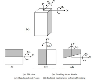
Columns are usually subjected to two bending moments about two perpendicular axes (X and Y) as well as an axial force in the vertical Z direction (see Figure 1).
With the shown sign convention, bending about X-axis causes compression in the top part and tension in the bottom region, whereas bending about Y-axis causes compression in the left-hand part and tension in the right part. For symmetric sections subjected to uniaxial bending, the neutral axis is parallel to the moment axis. In biaxial bending (d), the top-left part is subjected to double compression and the bottom right part is subjected to double tension. The remaining parts are subjected to combined compression and tension. This means that the two moments are not X Y Mx My P Y My X Mx (b) (c) (d) X Y Mx My independent but coupled. The resulting neutral axis is inclined with an angle depending on the moment values as well as the section properties. Interaction between the axial force P and the two bending moments Mx and My is represented by a 3D surface. The design surface is inside the nominal surface. The 3D surface is constructed by combining several interaction curves P-M at various neutral axis angles.
Various 2D scans can be extracted from the 3D surface:
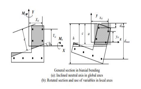
The figure shows a general section subjected to biaxial bending. With respect to the sign convention shown in the figure, the nominal force and moments in biaxial bending are given by:

B is the area of the concrete compression block. Xb and Yb are coordinates of the centroid of the compression block with respect to X and Y axes having the origin as the centroid of the gross section. Steel bars are described by their coordinates Xsi and Ysi. The compression block may have more than one part as and may contain parts of the possible voids present in the section. For each neutral axis angle, an interaction curve (meridian) P-Mx-My is constructed by varying the neutral axis depth from pure compression to pure tension. Calculations are complex and are usually carried out in local axes (b).
Biaxial bending analysis and design of columns is very complex and only some specific software can be used for this purpose such as RC-BIAX developed in KSU. Codes of practice such as ACI and SBC allow the use of approximate methods to check for biaxial bending. Among these is the reciprocal method of Bresler.
A column is a vertical structural member designed to transfer a compressive load. For example, a column might transfer loads from a ceiling, floor or roof slab or from a beam, to the foundations.
Columns also carry the bending moment about one or both axes of their cross-section.
Biaxial bending affects columns where the load is eccentric about both the axes in the plane of the column (eccentric load is a force placed upon a portion of a column which is not symmetric with its central axis, thereby producing bending).
For both rectangular and square columns, there are situations in which axial compression is accompanied by simultaneous bending about both principal axes of the section.
Design of Column Section
This chapter deals primarily with the IS code provisions for the design of columns, under various loading conditions. The design of column section can be made either by working stress method or by limit state method. The working stress method of design of column is based on the behaviour of structure at working loads ensuring that stresses in steel and concrete do not exceed their allowable values. The section is assumed to possess adequate safety against collapse. The limit state method of design of column is based on behaviour of structure at collapse, ensuring adequate margin of safety. The serviceability limits of deflection and cracking are assumed to be satisfied as columns, being compression members, have very small deflection and cracks.
Assumptions in Limit State Method Following are the basic assumptions in the Limit State Method. 1. The plane section normal to the axis of column before deformation, remains plane after deformation i.e., the strain at any point is proportional to its distance from the neutral axis. 2. The tensile strength of concrete is ignored. 3. The maximum compressive strain in concrete in axial compression is taken as 0.002. 4. The relationship between stress-strain distribution in concrete is assumed to be parabolic as shown in Fig.2.1. The maximum compressive stress is equal to 0.67 fck/ 1.5 or 0.446 fck, where 1.5 is the partial safety factor for concrete. 5. The stresses in reinforcement are derived from the representative actual stress-strain curve for the type of steel used. The partial factor of safely of 1.15 is taken for steel. Therefore, design strength is 0.87 fy, as shown in Fig.2.2. 6. The maximum compressive strain at the highly compressed extreme fibre in concrete subjected to axial compression and bending, but when there is no tension on the section, is taken as 0.0035 minus 0.75 times the strain at the least compressed extreme fibre.
The maximum compressive strain at the highly compressed extreme fibre in concrete subjected to axial compression and bending, when part of the section is in tension, is taken as 0.0035. Other codal provisions based on 15:456-2000 are as follows:
Minimum Eccentricity: - All columns in compression shall be designed for the minimum eccentricity
Emin = Unsupported Length / 500 + Lateral Dimension/30, Subject to a minimum of 20 mm. 2.3 Short Columns Under Axial Compression When the minimum eccentricity given by above equation is less than 0.05 times the lateral dimension, the members may be designed by the following equation.
Pu = 0.4 fck *Ac + 0.67 fy *Asc.
The above equation can be written as
Pu = 0.4 fck (Ag - p*Ag / 100) + 0.67 fy* p*Ag/100 or Pu / Ag = 0.4 fck (1 - p/100) + 0.67 fy* p / 100 or P„ /Ag - 0.4 fck + p/100 (0.67 fy - 0.4 fck)
where p = Percentage of total steel in section. fy = Characteristic strength of steel
Ag - Gross (iii; a of concrete section = b*D for rectangular section. - (7i*dia.*dia.)/4 for circular section
fck - Characteristic strength of concrete in 'SP-16',
Chart No. 24-26 are given for designing short columns in accordance with above equation.
Key Takeaways:
References:
1. McCormac, J.C., Nelson, J.K. Jr., Structural Steel Design. 3rd edition. Prentice Hall, N.J., 2003.
2. Galambos, T.V., Lin, F.J., Johnston, B.G., Basic Steel Design with LRFD, Prentice Hall, 1996
3. Segui, W. T., LRFD Steel Design, 2nd Ed., PWS Publishing, Boston.
4. Salmon, C.G. and Johnson, J.E., Steel Structures: Design and Behavior, 3rd Edition, Harper & Row, Publishers, New York, 1990.
5. Related Codes of Practice of BIS
6. NBC, National Building Code, BIS (2017).
7. ASCE, Minimum Design Loads for Buildings and Other Structures, ASCE 7-02, American Society of Civil Engineers, Virginia, 2002.
8. Subramanian, N. (2010). Steel Structures: Design and Practice, Oxford University Press.
9. Duggal, S.K. (2014). Limit State Design of Steel Structures, McGraw Hill.


