Unit-1
Consolidation of Soil - Introduction
Consolidation refers to the compression of settlement that the soil undergoes as response of placing loads on the ground.
These loads produce corresponding increases in the vertical effective stress.
Consolidation is a time-dependent process in some soil it may take long time to achieve complete settlement.
Consolidation is the gradual reduction in the volume of a partly or fully saturated soil under sustained loading and is mainly due to the expulsion of water from the soil pores.
This process of expulsion of water from soil due to excess pore pressure with gradual reduction in soil volume accompanied by transfer of pressure from water to soil particles is called the ‘process of consolidation’.
Compaction of soil is area compacted by the mechanical method to remove air voids in compacted soil this area of soil called compaction.
Consolidation is any process which involves a decrease in water content of saturated soil without replacement of water by air.
1. Initial consolidation — It is a comparatively a sudden reduction in soil volume on application of the load mainly due to expulsion and compression of air present in soil pores.
2. Primary consolidation — It is the main phase of compression due to expulsion of pore water and dissipation of excess pore pressure. It is a time settlement phenomenon.

3. Secondary Consolidation — Even after dissipation of the excess pore pressure, some compression of soil continues at a gradually reducing rate which is known as secondary consolidation. It is a complex process and is thought to be due to the adjustment of internal structure of the soil.
The consolidation process of a saturated clay layer undergoes as under.
Immediately, on application of a pressure increment Δp, it is entirely taken up by the water in the pores, causing an excess pore pressure, also called hydrodynamic pressure (represented by say u̅). Thus at t = 0, u̅ = Δp. At this stage, the pressure transferred to the soil grains is nil.
If this transferred pressure is represented by ΔP̅, then when t = 0, ΔP̅ = 0. At any time afterwards, ΔP = u̅ + ΔP̅, and with increasing time, u̅ decreases and ΔP̅ increases, till finally u̅ becomes zero when the consolidation gets completed, and then ΔP̅ becomes equal to ΔP̅.
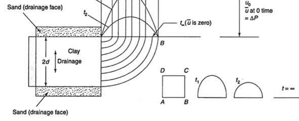
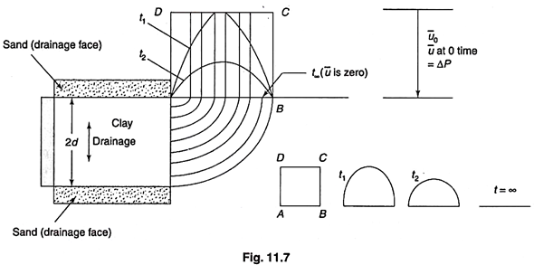
Figure illustrates for a clay layer, which is being drained at both ends. In this case, at time t = 0 or t∞ the excess hydrostatic pressure will immediately fall to zero at upper as well as at the lower ends, because it is permitting two-way drainage.
In the middle of the layer, however, full extra hydrostatic pressure will prevail, i.e., equal to u. Rectangle ABCD thus represents the initial hydrostatic excess pressure diagram.
At any other time say t1, t2…, the excess pressure diagram will be somewhat triangular, as the pressure at the centre will go on reducing, till it becomes zero at t = ∞. The excess hydrostatic pressure diagram or isochrones corresponding to t1, t2… t∞ would be as shown in Fig. 11.7.
The load transferred to the soil grains at any time, i.e., ΔP̅ can be worked out by subtracting the area of that curve from the total area ABCD. The ratio of this area to the area ABCD would eventually indicate the extent or the degree of consolidation at that time, and is usually expressed as percentage.
This degree of consolidation, U, at any time t after the start of consolidation process, can be expressed by the simple relation.
U = Δh/ΔH
Where Δh = compression at any time t.
ΔH = total ultimate compression
Alternatively, this can be expressed in terms of void ratio, as —

Where e0 is the initial void ratio (at the start of consolidation), ef is the final void ratio (at the end of consolidation) and e is the void ratio at any time t.
The process of primary consolidation can be explained with the help of the spring analogy given by terzaghi.
Fig shows a spring with a piston on its top. Let the length of the spring be z_{0} under a pressure of 10 units. Fig 5 units of pressure are added to its top, the spring will be compressed immediately to a length z_{1}. A further application of load will result in further decrease in the length of spring.
If this spring and piston is placed in a cylinder containing water up to the bottom of the piston, 10 units of pressure applied with valve open, water will be free of stress, since the whole load is carried by the spring alone.
If the pressure on the piston is increased to 15 units, and the valve is closed, the spring cannot deform si9nce water is incompressible. Hence the additional pressure of 5 units is entirely born by water.
Let,
σ = total pressure
σ' = pressure in the spring
ū = pressure in water
σ = σ' + ū
15= 10 + 5
Now, let the valve be opened slightly so that some water escapes and then valve is closed. Due to escape of some water, the piston moves down, the spring is compressed and hence some pressure out of 5 units borne by water is now transferred to the spring
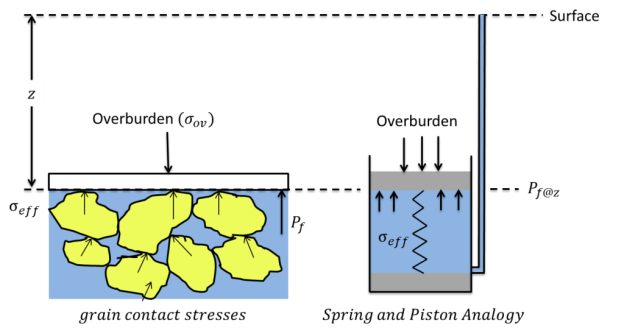
∴ 15 = (10 + Δσ') + (5 - Δσ')
Where,
Δσ' = transfer of pressure from water to spring
If the valve is completely opened, sufficient water will escape till the length of the spring is reduced to z_{1}. Thus, the whole 5 units of pressure is transferred from water to the spring. The water becomes free of pressure and spring carries the whole pressure.
This analogy can be applied to the consolidation process of soil mass containing soil- water system. The solid particles of the soil represent the spring while the voids filled with the water represent by the cylinder. The valve opening is represented by the permeability of the soil mass.
The compression of a spring mass system is analogous to the consolidation of a saturated fine grained soil deposit subjected to external pressure (∆σ) Soil Compressibility Compression of Sand.
Odeometer test
The simplest case of consolidation examined is the one-dimensional consolidation. In this case, the lateral strain of the soil mass is neglected. The testing procedure to quantify the critical soil properties associated with soil consolidation is the Oedometer Test. The term “Oedometer” derives from the Ancient Greek language and means “to swell”. The test is one of the most commonly conducted, and important, laboratory tests in geotechnical engineering. The Oedometer Test aims at measuring the vertical displacement of a cylindrical, saturated soil sample subjected to a vertical load while it is radially constrained. In the subsequent test, the incremental loading consolidation test is described. Note that there is also a constant rate of strain (CRS) test, that nowadays is becoming more popular
Test setup components
A typical Oedometer test set-up, shown in Figure 1, is composed of: ia consolidation cell, iia loading frame , and iii) .a deformation measurement mechanism.
The consolidation cell consists of the following components:
Typical diameter (D) to height (H) ratios of the soil samples are D/H = 3 - 4. The cross-section area of the soil specimen may be 20, 35 or 50 cm2 (D = 5 - 8 cm) and its height is H = 2 - 2.5 cm.
The loading frame configuration is composed of a loading beam and dead weights. The configuration allows for a constant load to be maintained indefinitely. The application of the load causes deformation of the loading frame, the porous stones and the soil sample. Since the test is intended to measure only the deformation of the soil, the other movements (machine deflections) must be measured and later subtracted from the total deformation. This is achieved by measuring the deflection of the set up using an aluminum sample, which is characterized by linear elastic,and thus known, response.
The vertical deformation measurements of the soil specimen is performed using a dial gauge (most often) or an electronic instrument.
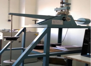
Figure: Typical Oedometer test set-up
Testing Procedure
The typical testing procedure consists of the following steps:Position the dial gauge (or electronic instrument)
The load is maintained for a period of 24 hours (in certain clays the required time is 48 hours) during which the soil consolidates with drainage from the porous stones. Afterwards, the applied load is increased incrementally by doubling the applied stress at each stage. The number of the load stages and the maximum stress applied depends on the stress range of interest. During the loading process, water is provided into the cell so that the specimen remains fully saturated. At each loading stage, readings of deformation are taken systematically to develop a time-settlement curve. That is, after the application of each load, the deformation is measured at 6, 15, 30 seconds, then at 1, 2, 4, 8, 16, 30 min and at 1, 2, 4, 8 and 24 hours, respectively. When the maximum load is reached, and possibly in a load increment in between, an unloading stage is introduced that may be conducted in one or multiple steps; typically, the load is reduced by a factor of 4 at each step. When the test is completed, the final height of the sample and its water content are measured.
The following soil properties are derived from the Oedometer Test:
The Compression Index CC: CC is an index associated with the compressibility of the soil. In particular, it is measured as the slope of the curve between void ratio and effective stress. The void ratio is plotted in a normal scale whereas the effective stress in a logarithmic scale. A typical compression curve in terms of void ratio—effective stress is presented in Figure 2. The inclination of the “virgin” part of the curve denotes the Compression Index, CC.
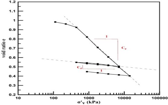
Figure 2: Typical diagram of void ratio - effective stress correlation obtained by Oedometer Test. The Compression CC and Recompression Cr indices are also presented.
Therefore, CC is:
CC = Δe / Δlog (σ')
CC usually ranges from 0.1 to 10 and has no units. For normally consolidated clays the index commonly ranges between 0.20 to 0.50 and for silts between 0.16-0.24. For sands, the index ranges between 0.01 to 0.06, although this is not a particularly meaningful parameter for a sand.
Some empirical expressions that relate the Compression Index, CC, with the Liquid limit (LL) and Plasticity Index (PI) of the soil, are the following:
The coefficient of consolidation, CV can readily be estimated from the time-settlement curve using graphical methods. There are two, most commonly used, methodologies:
The coefficient of consolidation, CV, is determined by estimating the time at 50% consolidation (t50), as shown in the short animation/presentation below. Then, CV can be estimated as:
CV = 0.917 * (H2dr / t50)
where Hdr is the drainage path. Given the initial height of the specimen (Hi) and the compression of the soil sample at 50% consolidation (ΔΗ), the drainage path (for double drainage), Hdr, is computed as:
Hdr = (Hi - ΔΗ) / 2
1. Immediate settlement.
2. Primary consolidation settlement
3. Secondary consolidation settlement (Creep settlement)
St = Si + Sc + Ssc
Primary Consolidation Settlement
It occurs due to expulsion of pore water from the voids of a saturated soil. In case of saturated fine-grained soils, the deformation is due to squeezing of water from the pores leading to rearrangement of soil particles. The movement of pore water depends on the permeability and dissipation of pore water pressure. With the passage of time the pore water pressure dissipates, the rate of flow decreases and finally the flow of water ceases. During this process there is gradual dissipation of pore water pressure and a simultaneous increase of effective stress as shown in Fig 1. The consolidation settlement occurs from the time water begins move out from the pores to the time at which flow ceases from the voids.
This is also the time from which the excess pore water pressure starts reducing (effective stress increase) to the time at which complete dissipation of Saturated clay GL Settlement Time Consolidation of Soils 06CV54 4 excess pore water pressure (total stress equal to effective stress). This time dependent compression is called “Consolidation settlement” Primary consolidation is a major component of settlement of fine-grained saturated soils and this can be estimated from the theory of consolidation. In case of saturated soil mass the applied stress is borne by pore water alone in the initial stages ∴
At t = 0 ∆σ = ∆u ∆σ´= 0 With passage of time water starts flowing out from the voids as a result the excess pore water pressure decreases and simultaneous increase in effective stress will takes place.
The volume change is basically due to the change in effective stress ∆σ´. After considerable amount of time (t =∞) flow from the voids ceases the effective stress stabilizes and will be is equal to external applied total stress (∆σ) and this stage signifies the end of primary consolidation. At t = t1 ∆σ = ∆σ´+ ∆u At t = ∞∆σ = ∆σ´ ∆u = 0 (End of primary consolidation
Immediate consolidation settlement
Predictions of consolidation settlement using the one-dimensional method are based on the results of oedometer tests using representative samples of the clay. Due to the confining ring the net lateral strain in the test specimen is zero and for this condition the initial excess pore water pressure is equal theoretically to the increase in total vertical stress, i.e. the pore pressure coefficient A is equal to unity.
In this case, the immediate vertical displacement is given by
Si CsqB 1 v 2 – Eu ------------- Ë ¯
where Si = immediate settlement of a point on the surface Cs = shape and rigidity factor q = equivalent uniform stress on the footing (total load/footing area) B = characteristic dimension of the footing v = Poisson’s ratio Eu = undrained elastic modulus (Young’s modulus) The coefficient Cs is a function of the shape and rigidity of the loaded
In practice the condition of zero lateral strain is satisfied approximately in the cases of thin clay layers and of layers under loaded areas which are large compared with the layer thickness. In many practical situations, however, significant lateral strain will occur and the initial excess pore water pressure will depend on the in-situ stress conditions and the value of the pore pressure coefficient A (which will not be equal to unity).. Settlement by the Skempton–Bjerrum method 237In cases in which the lateral strain is not zero, there will be an immediate settlement, under undrained conditions, in addition to the consolidation settlement.
Immediate settlement is zero if the lateral strain is zero, as assumed in the one-dimensional method of calculating settlement. In the Skempton–Bjerrum method [22], the total settlement (s) of a foundation on clay is given by s ¼ si þ sc where si ¼ immediate settlement, occurring under undrained conditions, and sc ¼ consolidation settlement, due to the volume reduction accompanying the gradual dissipation of excess pore water pressure.
The immediate settlement (si) can be estimated from the results of elastic theory (Section 5.3). The value of Poisson’s ratio () relevant to undrained conditions in a fully saturated clay is taken to be 0.5. The undrained Young’s modulus (Eu) must be estimated from the results of laboratory tests, in-situ load tests or pressuremeter tests. However, for most soils, the modulus increases with depth. Use of a constant value of Eu overestimates immediate settlement.
Secondary Consolidation Settlement: -
This is also called Secondary compression (Creep). “It is the change in volume of a fine-grained soil due to rearrangement of soil particles (fabric) at constant effective stress”. The rate of secondary consolidation is very slow when compared with primary consolidation.
Effective stress versus Time ∆σ’ Time Primary consolidation Secondary consolidation of Soils.
Excess Pore water Pressure (∆u) “It is the pressure in excess of the equilibrium pore water pressure”. It is represented as ∆u. ∆u= h γw Where h --- Piezometric head γw2 --- Unit weight of water.
When saturated soil mass is subjected to external load decrease in volume takes place due to rearrangement of soil particles. Reduction in volume is due to expulsion of water from the voids. The volume change depends on the rate at which water is expelled and it is a function of permeability.
The total vertical deformation (Consolidation settlement) depends on
1. Magnitude of applied pressure (σ∆).
Consolidation settlement is calculated separately from immediate settlement, as suggested by Eq. (19.1). When a load is applied to the ground surface, there is a tendency for volumetric compression of the underlying soils. For saturated materials, an increase in pore water pressure occurs immediately upon load application. Consolidation is then the process by which there is a reduction in volume due to the expulsion of water from the pores of the soil. The dissipation of excess pore water pressure is accompanied by an increase in effective stress and volumetric strain. Analysis of the resulting settlement is greatly simplified if it is assumed that such strain is one-dimensional, occurring only in the vertical direction.
This assumption of one-dimensional compression is considered to be reasonable when (1) the width of the loaded area exceeds four times the thickness of the clay stratum, (2) the depth to the top of the clay stratum exceeds twice the width of the loaded area, or (3) the compressible material lies between two stiffer soil strata whose presence tends to reduce the magnitude of horizontal strains [Leonards, 1976]. Employing the assumption of one-dimensional compression, the consolidation settlement of a cohesive soil stratum is generally calculated in two steps: 1. Calculate the total (or “ultimate”) consolidation settlement, Sc, corresponding to the completion of the consolidation process. 2. Using the theory of one-dimensional consolidation, calculate the fraction of Sc that will have occurred by the end of the service life of the structure. This fraction is the component of consolidation settlement to be used i
Total Consolidation Settlement Total one-dimensional consolidation settlement, Sc, results from a change in void ratio, De, over the depth of the consolidating layer. The basic equation for calculating the total consolidation settlement of a single compressible layer is
Sc DeHo 1 e + o = -----------
where eo is the initial void ratio and Ho is the initial height of the compressible layer
where eo is the initial void ratio and Ho is the initial height of the compressible layer. Consolidation settlement is sometimes calculated using Ho for the entire consolidating stratum and stress conditions acting at the midheight. This procedure will underestimate the actual settlement, and the error will increase with the thickness of the clay. As De generally varies with depth, settlement calculations can be improved by dividing the consolidating stratum into n sublayers for purposes of analysis. Equation (19.4) is then applied to each sublayer and the cumulative settlement is computed using the following equation:
Sc Dei Hoi 1 e + ois --------------- i = 1 n =
where Dei , is the change in void ratio, Hoi is the initial thickness, and eoi is the initial void ratio of the itch sublayer. The appropriate Dei for each sublayer within the compressible soil must now be determined. To begin, both the initial vertical effective stress, s ¢vo, and the final vertical effective stress (after excess pore pressures have fully dissipated), s ¢vf , are needed. The distribution of s ¢vow with depth is usually obtained by subtracting the in situ pore pressure from the vertical total stress, sv . Vertical total stress at a given depth is calculated using the following equation:
sv g jzj j = 1 m = Â
where
gj = unit weight of the jth stratigraphic layer
zj = thickness of the jth stratigraphic layer
m = number of layers above the depth of interest
References:
1. Soil Mechanics by Craig R.F., Chapman & Hall
2. Fundamentals of Soil Engineering by Taylor, John Wiley & Sons
3. An Introduction to Geotechnical Engineering, by Holtz R.D. and Kovacs, W.D., Prentice Hall, NJ
4. Principles of Geotechnical Engineering, by Braja M. Das, Cengage Learning
5. Principles of Foundation Engineering, by Braja M. Das, Cengage Learning
6. Essentials of Soil Mechanics and Foundations: Basic Geotechnics by David F. McCarthy
7. Soil Mechanics in Engineering Practice by Karl Terzaghi, Ralph B. Peck, and Gholamreza Mesri.
8. Geotechnical Engineering: Principles and Practices of Soil Mechanics and Foundation
Engineering (Civil and Environmental Engineering) by V.N.S. Murthy