Unit – 2
Orthographic Projections
If straight lines are drawn from various points on the contour of an object to meet a plane, the object is said to be projected on that plane. The figure formed by joining, in correct sequence, the points at which these lines meet the plane, is called the projection of the object. The lines from the object to the plane are called projectors.
Methods of Projection:
Following four methods of projection are commonly used,
1) Orthographic projection.
2) Isometric projection.
3) Oblique projection.
4) Perspective projection.
In the above methods 2, 3 and 4 represent the object by a pictorial view as eyes see it. In these methods of projection, a three-dimensional object is represented on a projection plane by one view only, while in the orthographic projection an object is represented by two or three views on the mutual perpendicular projection planes. Each projection view represents two dimensions of an object. For the complete description of the three-dimensional object at least two or three views are required.
Orthographic Projection:
Theory of orthographic projection:
Let us suppose that a transparent plane has been set up between an object and the station point of an observer's eye (Fig. 1). The intersection of this plane with the rays formed by lines of sight from the eye to all points of the object would give a picture that is practically the same as the image formed in the eye of the observer. This is perspective projection.

Figure 1 Perspective projection. The rays of the projection converge at the station point from which the object is observed.
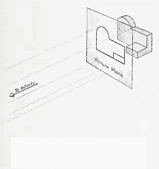
If the observer would then walk backward from the station point until he reached a theoretically infinite distance, the rays formed by lines of sight from his eye to the object would grow longer and finally become infinite in length, parallel to each other, and perpendicular to the picture plane. The image so formed on the picture plane is what is known as "orthographic projection." See Fig.
2.

Orthographic projection.
Basically, orthographic projections could be defined as any single projection made by dropping perpendiculars to a plane. However, it has been accepted through long usage to mean the combination of two or more such views, hence the following definition has been put forward: Orthographic projection is the method of representing the exact shape of an object by dropping perpendiculars from two or more sides of the object to planes, generally at right angles to each other; collectively, the views on these planes describe the object completely. (The term "orthogonal" is sometimes used for this system of drawing.)
Orthographic views:
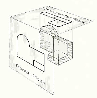
The rays from the picture plane to infinity may be discarded and the picture, or "view," thought of as being found by extending perpendiculars to the plane from all points of the object, as in Fig. 3. This picture, or projection on a frontal plane, shows the shape of the object when viewed from the front, but it does not tell the shape or distance from front to rear. Accordingly, more than one projection are required to describe the object.

The frontal plane of projection. This produces the front view of the object.
In addition to the frontal plane, imagine another transparent plane placed horizontally above the object, as in Fig. 4. The projection on this plane, found by extending perpendiculars to it from the object, will give the appearance of the object as if viewed from directly above and will show the distance from front to rear.

The frontal and horizontal planes of projections. Projection on the horizontal plane produces the top view of the object.
If this horizontal plane is now rotated into coincidence with the frontal plane, as in Fig. 5, the two views of the object will be in the same plane, as if on a sheet of paper.

Figure 5 The horizontal plane rotated into the same plane as the frontal plane.
Now imagine a third plane, perpendicular to the first two (Fig. 6). This plane is called a "profile plane," and a third view can be projected on it. This view shows the shape of the object when viewed from the side and the distance from bottom to top and front to rear.

The three planes of projection: frontal, horizontal and profile. Each is perpendicular to other two.
The horizontal and profile planes are shown rotated into the same plane as the frontal plane (again thought of as the plane of the drawing paper) in Fig. 7. Thus, related in the same plane, they give correctly the three-dimensional shape of the object.

The horizontal and profile planes rotated into the same plane as the frontal plane. This makes it possible to draw three views of the object.
In orthographic projection the picture planes are called "planes of projection"; and the perpendiculars, "projecting lines" or "projectors."
A straight line is the shortest distance between two points. Hence, the projections of a straight line may be drawn by joining the respective projections of its ends which are points.
The position of a straight line may also be described with respect to the two reference planes. It may be:
1. Parallel to one or both the planes.
2. Contained by one or both the planes.
3. Perpendicular to one of the planes.
4. Inclined to one plane and parallel to the other.
5. Inclined to both the planes.
6. Projections of lines inclined to both the planes.
7. Line contained by a plane perpendicular to both the reference planes.
8. True length of a straight line and its inclinations with the reference planes.
9. Traces of a line.
10. Methods of determining traces of a line.
11. Traces of a line, the projections of which are perpendicular to xy.
12. Positions of traces of a line.
Line parallel to one or both the planes:

Figure
(a) Line AB is parallel to the H.P.
a and b are the top views of the ends A and B respectively. It can be clearly seen that the figure ABba is a rectangle. Hence, the top view ab is equal to AB.
a'b' is the front view of AB and is parallel to xy.
(b) Line CD is parallel to the V.P. The line c'd' is the front view and is equal to CD; the top view cd is parallel to xy.
(c) Line ff is parallel to the H.P. And the V.P. Ef is the top view and e'f' is the front view; both are equal to ff and parallel to xy.
Hence, when a line is parallel to a plane, its projection on that plane is equal to its true length; while its projection on the other plane is parallel to the reference line.
Line contained by one or both the planes:

Figure
Line AB is in the H.P. Its top view ab is equal to AB; its front view a' b' is in xy.
Line CD is in the V.P. Its front view c'd' is equal to CO; its top view cd is in xy.
Line ff is in both the planes. Its front view e' f' and the top view ef coincide with each other in xy.
Hence, when a line is contained by a plane, its projection on that plane is equal to its true length; while its projection on the other plane is in the reference line.
Line perpendicular to one of the planes:
When a line is perpendicular to one reference plane, it will be parallel to the other.

(a) Line AB is perpendicular to the H.P. The top views of its ends coincide in the point a. Hence, the top view of the line AB is the point a. Its front view a' b' is equal to AB and perpendicular to xy.
(b) Line CD is perpendicular to the V.P. The point d' is its front view and the line cd is the top view. Cd is equal to CD and perpendicular to xy.
Hence, when a line is perpendicular to a plane its projection on that plane is a point; while its projection on the other plane is a line equal to its true length and perpendicular to the reference line.
In first-angle projection method, when top views of two or more points coincide, the point which is comparatively farther away from xy in the front view will be visible; and when their front views coincide, that which is farther away from xy in the top view will be visible.
In third-angle projection method, it is just the reverse. When top views of two or more points coincide the point, which is comparatively nearer xy in the front view will be visible; and when their front views coincide, the point which is nearer xy in the top view will be visible.
Line inclined to one plane and parallel to the other:

Figure
The inclination of a line to a plane is the angle which the line makes with its projection on that plane.
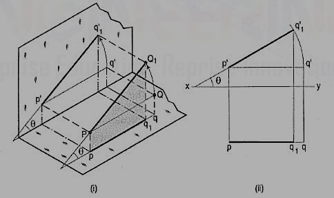
Line PQ1 [fig. 22 (i)] is inclined at an angle 8 to the H.P. And is parallel to the V.P. The inclination is shown by the angle 8 which PQ1 makes with its own projection on the H.P., viz. The top view pq1.
The projections [fig. 22 (ii)] may be drawn by first assuming the line to be parallel to both the H.P. And the V.P. Its front view p'q' and the top view pq will both be parallel to xy and equal to the true length. When the line is turned about the end P to the position PQ1 so that it makes the angle 8 with the H.P. While remaining parallel to the V.P., in the front view the point q' will move along an arc drawn with p' as center and p'q' as radius to a point q'1 so that p'q'1 makes the angle 8 with xy. In the top view, q will move towards p along pq to a point q1 on the projector through q'1. p'q'1 and pq1 are the front view and the top view respectively of the line PQ1.
Line inclined to both the planes:
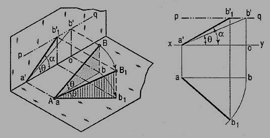
A line AB (fig. 23) is inclined at θ to the H.P. And is parallel to the V.P. The end A is in the H.P. AB is shown as the hypotenuse of a right-angled triangle, making the angle θ with the base.

Figure
The top view ab is shorter than AB and parallel to xy. The front view a'b' is equal to AB and makes the angle θ with xy.
Keeping the end, A fixed and the angle θ with the H.P. Constant, if the end B is moved to any position, say B1, the line becomes inclined to the V.P. Also.
In the top view, b will move along an arc, drawn with a as center and ab as radius, to a position b1. The new top view ab1 is equal to ab but shorter than AB.
In the front view, b' will move to a point b'1 keeping its distance from xy constant and equal to b'o; i.e., it will move along the line pq, drawn through b' and parallel to xy. This line pq is the locus or path of the end B in the front view. b'1 will lie on the projector through b1. The new front view a'b'1 is shorter than a'b' (i.e., AB) and makes an angle a with xy. a is greater than θ.
Thus, if the inclination θ of AB with the H.P.is constant, even when it is inclined to the V.P.
(i) its length in the top view, viz. Ab remains constant; and
(ii) the distance between the paths of its ends in the front view, viz. b'o remains constant.

Figure
b) The same line AB (fig. 24) is inclined at ϕ to the V.P. And is parallel to the H.P. Its end A is in the V.P. AB is shown as the hypotenuse of a right-angled triangle making the angle ϕ with the base.
The front view a'b'2 is shorter than AB and parallel to xy. The top view ab2 is equal to AB and makes an angle ϕ with xy.
Keeping the end, A fixed and the angle ϕ with the V.P. Constant, if B is moved to any position, say B3, the line will become inclined to the H.P. Also.
In the front view, b'2, will move along the arc, drawn with a' as center and a'b'2 as radius, to a position b'3. The new front view a'b'3 is equal to a'b'2 but is shorter than AB.
In the top view, b2 will move to a point b3 along the line rs, drawn through b2 and parallel to xy, thus keeping its distance from the path of a, viz. b2o constant. Rs is the locus or path of the end B in the top view. The point b3 lies on the projector through b'3. The new top view ab3 is shorter than ab2 (i.e., AB) and makes an angle β with xy. β is greater than ϕ.
Here also we find that, if the inclination of AB with the V.P. Does not change, even when it becomes inclined to the H.P.
(i) its length in the front view, viz. a'b'2 remains constant; and
(ii) the distance between the paths of its ends in the top view, viz. b2o remains constant.
Hence, when a line is inclined to both the planes, its projections are shorter than the twe length and inclined to xy at angles greater than the true inclinations. These angles viz. α and β are called apparent angles of inclination.
References:
1 Bhatt N.D., Panchal V.M. & Ingle P.R., (2014), Engineering Drawing, Charotar Publishing House
2 Shah, M.B. &Rana B.C. (2008), Engineering Drawing And Computer Graphics, Pearson Education
3 Agrawal B. & Agrawal C. M. (2012), Engineering Graphics, Tmh Publication
4 Narayana, K.L. & P Kannaiah (2008), Text Book On Engineering Drawing, Scitech publishers
5 (Corresponding Set Of) Cad Software Theory And User Manuals