Unit – 4
Sections And Sectional Views of Right Angular Solids
Invisible features of an object are shown by dotted lines in their projected views. But when such features are too many, these lines make the views more complicated and difficult to interpret. In such cases, it is customary to imagine the object as being cut through or sectioned by planes. The part of the object between the cutting plane and the observer is assumed to be removed and the view is then shown in section.
The imaginary plane is called a section plane or a cutting plane. The surface produced by cutting the object by the section plane is called the section. It is indicated by thin section lines uniformly spaced and inclined at 45°.
The projection of the section along with the remaining portion of the object is called a sectional view. Sometimes, only the word section is also used to denote a sectional view.
(1) Section planes:
Section planes are generally perpendicular planes. They may be perpendicular to one of the reference planes and either perpendicular, parallel or inclined to the other plane. They are usually described by their traces. It is important to remember that the projection of a section plane, on the plane to which it is perpendicular, is a straight line. This line will be parallel, perpendicular or inclined to xy, depending upon the section plane being parallel, perpendicular or inclined respectively to the other reference plane.
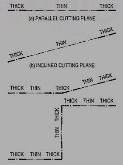
Figure 1
As per latest 8.1.S. Convention (SP: 46-2003), the cutting-plane line should be drawn as shown in fig. 1.
(2) Sections: The projection of the section on the reference plane to which the section plane is perpendicular, will be a straight-line coinciding with the trace of the section plane on it. Its projection on the other plane to which it is inclined is called apparent section. This is obtained by
(i) projecting on the other plane, the points at which the trace of the section plane intersects the edges of the solid and
(ii) drawing lines joining these points in proper sequence.
(3) True shape of a section: The projection of the section on a plane parallel to the section plane will show the true shape of the section. Thus, when the section plane is parallel to the H.P. Or the ground, the true shape of the section will be seen in sectional top view. When it is parallel to the V.P., the true shape will be visible in the sectional front view.
But when the section plane is inclined, the section must be projected on an auxiliary plane parallel to the section plane, to obtain its true shape. When the section plane is perpendicular to both the reference planes, the sectional side view will show the true shape of the section. In this chapter sections of different solids are explained in stages by means of typical problems as follows:
1. Sections of prisms
2. Sections of pyramids
3. Sections of cylinders
4. Sections of cones
5. Sections of spheres.
Sections of Prisms:
These are illustrated according to the position of the section plane with reference
To the principal planes as follows:
(1) Section plane parallel to the V.P.
(2) Section plane parallel to the H.P.
(3) Section plane perpendicular to the H.P. And inclined to the V.P.
(4) Section plane perpendicular to the V.P. And inclined to the H.P.
Sections of Pyramids:
The following cases are discussed in details.
(1) Section plane parallel to the base of the pyramid.
(2) Section plane parallel to the V.P.
(3) Section plane perpendicular to the V.P. And inclined to the H.P.
(4) Section plane perpendicular to the H.P. And inclined to the V.P.
Sections of Cylinders:
It consists of following two cases:
(1) Section plane parallel to the base
(2) Section plane parallel to the axis
Sections of Cones:
(1) Section plane parallel to the base of the cone.
(2) Section plane passing through the apex of the cone.
(3) Section plane inclined to the base of the cone at an angle smaller than the angle of inclination of the generators with the base.
(4) Section plane parallel to a generator of the cone.
(5) Section plane inclined to the base of the cone at an angle greater than the angle of inclination of the generators with the base.
Section parallel to the VP
Problem 1:
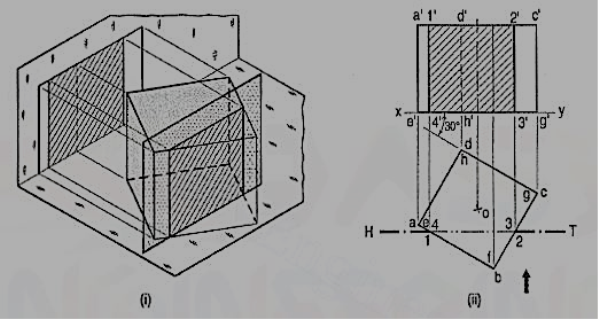
A cube of 35 mm long edges is resting on the H.P. On one of its faces with a vertical face inclined at 30° to the V.P. It is cut by a section plane parallel to the V.P. And 9 mm away from the axis and further away from the V.P. Draw its sectional front view and the top view.
In fig.2 (i), the section plane is assumed to be transparent and the cube is shown with the cut-portion removed. Four edges of the cube are cut and hence, the section is a figure having four sides.
Draw the projections of the whole cube in the required position [fig.2(ii)].As the section plane is parallel to the V.P., it is perpendicular to the H.P.; hence, the section will be a line in the top view coinciding with the H.T. Of the section plane.
(i) Draw a line H.T. In the top view (to represent the section plane) parallel to xy and 9 mm from o.
(ii) Name the points at which the edges are cut, viz. Ab at 1, be at 2, gf at 3 and fe at 4.
(iii) Project these points on the corresponding edges in the front view and join them in proper order.
As the section plane is parallel to the V.P., figure 1' 2' 3' 4' in the front view, shows the true shape of the section.
Show the views by dark but thin lines, leaving the lines for the cut-portion fainter.
(iv) Draw section lines in the rectangle for the section.
(2) Section plane parallel to the H.P.
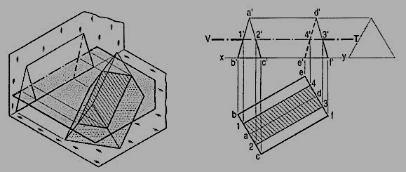
Problem 2 (fig. 3): A triangular prism, base 30 mm side and axis 50 mm long, is lying on the H.P. On one of its rectangular faces with its axis inclined at 30° to the V.P. It is cut by a horizontal section plane, at 12 mm above the ground. Draw its front view and sectional top view.
As the section plane is horizontal, i.e. parallel to the H.P., it is perpendicular to the V.P. Hence, the section will be a line in the front view, coinciding with the V. T. Of the section plane.
(i) Therefore, draw a line V.T. In the front view to represent the section plane, parallel to xy and 12 mm above it.
(ii) Name in correct sequence, points at which the edges are cut viz. a'b' at 1 ', a'c' at 2', d'f' at 3' and d'e' at 4'.
(iii) Project these points on the corresponding lines in the top view and complete the sectional top view by joining them in proper order.
As the section plane is parallel to the H.P., the figure 1 2 3 4 (in the top view) is the true shape of the section.
(3) Section plane perpendicular to the H.P. And inclined to the V.P.
Problem 3. (fig.): A cube in the same position as in problem 1, is cut by a section plane, inclined at 60° to the V.P. And perpendicular to the H.P., so that the face which makes 60° angle with the V.P. Is cut in two equal halves. Draw the sectional front view, top view and true shape of the section.
The section will be a line in the top view coinciding with the H.T. Of the section plane.
(i) Draw the projections of the cube. Draw a line H.T. In the top view inclined at 60° to xy and cutting the line ad (or be) at its mid-point.
(ii) Name the corners at which the four edges are cut and project them in the front view. As the section plane is inclined to the V.P., the front view of the section viz. 1' 2' 3' 4' does not reveal its true shape. Only the vertical lines show true lengths, while the true lengths of the horizontal lines are seen in the top view. The true shape of the section will be seen when it is projected on an auxiliary vertical plane, parallel to the section plane.
(iii) Therefore, draw a new reference line x1y1 parallel to the H.T. And project the section on it. The distances of the points from x1y1 should be taken equal to their corresponding distances from xy in the front view. Thus 4" and 3" will be on x1y1. 1" 4" and 2" 3" will be equal to 1' 4' and 2' 3' respectively. Complete the rectangle 1" 2" 3"4" which is the true shape of the section and draw section lines in it.

(4) Section plane perpendicular to the V.P. And inclined to the H.P.
Problem 4. (fig. 5): A cube in the same position as in problem 14-1 is cut by a section plane, perpendicular to the V.P., inclined at 45° to the H.P. And passing through the top end of the axis. (i) Draw its front view, sectional top view and true shape of the section. (ii) Project another top view on an auxiliary plane, parallel to the section plane.
The section will be a line in the front view.
(i) Draw a line V.T. In the front view, inclined at 45° to xy and passing through the top end of the axis. It cuts four edges, viz. a' e' at 1 ', a' b' at 2', c'd' at 3' and d'h' at 4'.
(ii) Project the top view of the section, viz. The figure 1 2 3 4. It does not show the true shape of the section, as the section plane is inclined to the H.P. To determine the true shape, an auxiliary top view of the section should be projected on an A.I.P. Parallel to the section plane.
(iii) Assuming the new reference line for the A.I.P. To coincide with the V.T., project the true shape of the section as shown by quadrilateral 11 21 31 41. The distances of all the points from the V.T. Should be taken equal to their corresponding distances from xy in the top view, e.g. 111' = e'1, 414' = h'4 etc.
(iv) To project an auxiliary sectional top view of the cube, draw a new reference line x1 y1, parallel to the V.T. The whole cube may first be projected and the points for the section may then be projected on the corresponding lines for the edges. Join these points in correct sequence and obtain the required top view.
(v) Draw section lines in the cut-surface, in the views where it is seen. Keep the lines for the removed edges thin and fainter.

Sections of Pyramids:
The following cases are discussed in details.
(1) Section plane parallel to the base of the pyramid.
(2) Section plane parallel to the V.P.
(3) Section plane perpendicular to the V.P. And inclined to the H.P.
(4) Section plane perpendicular to the H.P. And inclined to the V.P.
(1) Section plane parallel to the base of the pyramid.
Problem 5 A pentagonal pyramid, base 30 mm side and axis 65 mm long has its base horizontal and an edge of the base parallel to the V.P. A horizontal section plane cuts it at 25 mm above the base. Draw it’s from view and sectional top view.

(i) Draw the projections of the pyramid in the required position and show a line V.T. For the section plane, parallel to and 25 mm above the base. All the five slant edges are cut.
(ii) Project the points at which they are cut, on the corresponding edges in the top view. The point 2' cannot be projected directly as the line ob is perpendicular to xy. But it is quite evident from the projections of other points that the lines of the section in the top view, viz. 3-4, 4-5 and 5-1 are parallel to the edges of the base in their respective faces and that the points 1, 3, 4 and 5 are equidistant from o.
(iii) Hence, line 1-2 also will be parallel to ab and o2 will be equal to o1, o3 etc. Therefore, with o as centre and radius o1, draw an arc cutting ob at a point 2 which will be the projection of 2'. Complete the sectional top view in which the true shape of the section, viz. The pentagon 1, 2, 3, 4 and 5 is also seen.
(iv) Hence, when a pyramid is cut by a plane parallel to its base, the true shape of the section will be a figure, like the base; the sides of the section will be parallel to the edges of the base in the respective faces and the corners of the section will be equidistant from the axis.
(2) Section plane parallel to the V.P.
Problem 6 A triangular pyramid, having base 40 mm side and axis 50 mm long, is lying on the H.P. On one of its faces, with the axis parallel to the V.P. A section plane, parallel to the V.P. Cuts the pyramid at 6 mm from the axis. Draw its sectional front view and the top view.
(i) Draw the projections of the pyramid in the required position and show a line H.T. (for the cutting plane) in the top view parallel to xy and 6 mm from the axis.
(ii) Project points 1, 2 and 3 (at which the edges are cut) on corresponding edges in the front view and join them. Figure 1' 2' 3' shows the true shape of the section.

(3) Section plane perpendicular to the V.P. And inclined to the H.P.
Problem 7: A square pyramid, base 40 mm side and axis 65 mm long, has its base on the H.P. And all the edges of the base equally inclined to the V.P. It is cut by a section plane, perpendicular to the V.P., inclined at 45° to the H.P. And bisecting the axis. Draw its sectional top view, sectional side view and true shape of the section.
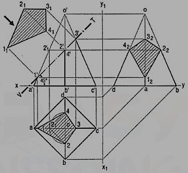
(i) Draw the projections of the pyramid in the required position. The section plane will be seen as a line in the front view. Hence, draw a line V.T. Through the mid-point of the axis and inclined at 45° to xy. Name in correct sequence the points at which the four edges are cut and project them in the top view. Here also, points 2' and 4' cannot be projected directly.
Hence, assume a horizontal section through 2' and draw a line parallel to the base, cutting o' a' at 2'1. Project 2'1 to 21 on oa in the top view. From 21 draw a line parallel to ab and cutting ob at a point 2. Or, with o as centre and radius o 21, draw an arc cutting ob at 2 and ob at 4. Complete the section 1 2 3 4 by joining the points and draw section lines in it.
(ii) Assuming the V.T. To be the new reference line, draw the true shape of the section. Project the side view from the two views. The removed portion of the pyramid may be shown by thin and faint lines.
(4) Section plane perpendicular to the H.P. And inclined to the V.P.
Problem 8 (fig. 9) A pentagonal pyramid has its base on the H.P. And the edge of the base nearer the V.P., parallel to it. A vertical section plane, inclined at 45° to o the V.P., cuts the pyramid at 6 mm from the axis. Draw the top view, sectional front view and the auxiliary front view on an A. V.P. Parallel to the section plane. Base of the pyramid 30 mm side; axis 50 mm long.

The section plane will be a line in the top view. It is to be at 6 mm from the axis.
i) Draw a circle with o as center and radius equal to 6mm.
Ii) Draw a line H.T. Tangent to this circle and inclined at 45° to xy. It can be drawn in four different positions, of which any one may be selected.
Iii) Project points 1, 2 etc. from the top view to the corresponding edges in the front view. Here again, point 2 cannot be projected directly. With centre o and radius o2 draw an arc cutting any one of the slant edges, say oc at 21. Project 21 to 2'1 on o'c'.
(iv) Through 2'1, draw a line parallel to the base, cutting o' b' at 2'. Then 2' is the required point. Complete the view. It will show the apparent section.
(v) Draw a reference line x1y1 parallel to the H.T. And project an auxiliary sectional front view which will show the true shape of the section also.
Sections of Cylinders:
It consists of following three cases:
(1) Section plane parallel to the base
(2) Section plane parallel to the axis
(1) Section plane parallel to the base:
When a cylinder is cut by a section plane parallel to the base, the true shape of the section is a circle of the same diameter.
(2) Section plane parallel to the axis:
When a cylinder is cut by a section plane parallel to the axis, the true shape of the section is a rectangle, the sides of which are respectively equal to the length of the axis and the length of the section plane within the cylinder (fig. 10). When the section plane contains the axis, the rectangle will be of the maximum size.

Problem 9: A cylinder of 40 mm diameter, 60 mm height and having its axis vertical, is cut by a section plane, perpendicular to the V.P., inclined at 45° to the H.P. And intersecting the axis32 mm above the base. Draw its front view, sectional top view, sectional side view and true shape of the section.
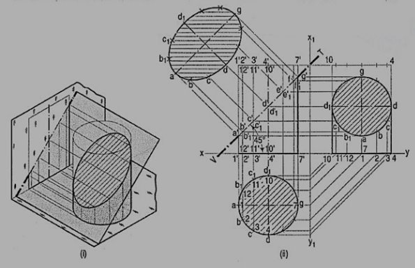
As the cylinder has no edges, many lines representing the generators may be assumed on its curved surface by dividing the base-circle into, say 12 equal parts.
(i) Name the points at which these lines are cut by the V.T. In the top view, these points lie on the circle and hence, the same circle is the top view of the section. The width of the section at any point, say c', will be equal to the length of the chord cc1 in the top view.
(ii) The true shape of the section may be drawn around the center line ag drawn parallel to V.T. As shown. It is an ellipse the major axis of which is equal to the length of the section plane viz. a'g', and the minor axis equal to the diameter of the cylinder viz. Dd1.
(iii) Project the sectional side view as shown. The section will be a circle because the section plane makes 45° angle with xy.
Sections of Cones:
(1) Section plane parallel to the base of the cone.
(2) Section plane passing through the apex of the cone.
(3) Section plane inclined to the base of the cone at an angle smaller than the angle of inclination of the generators with the base.
(4) Section plane parallel to a generator of the cone.
(5) Section plane inclined to the base of the cone at an angle greater than the angle of inclination of the generators with the base.
(1) Section plane parallel to the base of cone:
The cone resting on the H.P. On its base [fig.] is cut by a section plane parallel to the base. The true shape of the section is shown by the circle in the top view, whose diameter is equal to the length of the section viz. a'a'. The width of the section at any point, say b', is equal to the length of the chord bb1.
Problem:
Fig.(ii) To locate the position in the top view of any given point p' in the front view of the above cone.
Method I:
(i) Through p', draw a line r'r' parallel to the base.
(ii) With o as center and diameter equal to r'r', draw a circle in the top view.
(iii) Project p' to points p and p1 on this circle. p is the top view of p'. p1 is the top view of another point p'1 on the back side of the cone and coinciding with p'. The chord pp1 shows the width of the horizontal section of the cone at the point p'. This method may be called the circle method.

Method II:
When the position of a point in the top view say q is given, its front view q' can be determined by reversing the above process.
(i) With centre o and radius oq, draw a circle cutting the horizontal centre line at s.
(ii) Through s, draw a projector cutting the slant side o'1' at s'.
(iii) Draw the line s's' parallel to the base, intersecting a projector through q at the required point q'.
(2) Section plane passing through the apex of the cone:
Problem
[fig.]: A cone, diameter of base 50 mm and axis 50 mm long is resting on its base on the H.P. It is cut by a section plane perpendicular to the V.P., inclined at 75° to the H.P. And passing through the apex. Draw its front view, sectional top view and true shape of the section.
Draw the projections of the cone and on it, show the line V. T. For the section plane.
Mark many points a', b' etc. on the V.T. And project them to points a, b etc. in the top view by the circle method. It will be found that these points lie on a straight line through o.
Thus, od is the top view of the line or generator o'd' and triangle odd1 is the top view of the section. The width of the section at any point b' on the section is the line bb1, obtained by projecting b' on this triangle. This method is called the generator method.
Project the true shape of the section. It is an isosceles triangle, the base of which is equal to the length of the chord on the base-circle and the altitude is equal to the length of the section plane within the cone.

(3) Section plane inclined to the base of the cone at an angle smaller than the angle of inclination of the generators with the base:
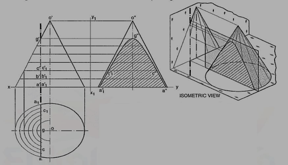
Problem 14-24. A cone, base 75 mm diameter and axis 80 mm long is resting on its base on the H.P. It is cut by a section plane perpendicular to the V.P., inclined at 45° to the H.P. And cutting the axis at a point 35 mm from the apex. Draw its front view, sectional top view, sectional side view and true shape of the section.
Draw a line V.T. In the required position in the front view of the cone.
(i) Generator method [fig.]:
(a) Divide the base-circle into many equal parts, say 12. Draw lines (i.e. generators) joining these points with o. Project these points on the line representing the base in the front view.
(b) Draw lines o' 2', o' 3' etc. cutting the line for the section at points b', c' etc. Project these points on the corresponding lines in the top view. For example, point b' on o' 2', also represents point b' 1 on o'-12' which coincides with o'-12'. Therefore, project b' to b on o 2 and to b1 on o'-12'. b and b1 are the points on the section (in the top view).
(c) Similarly, obtain other points. Point d' cannot be projected directly. Hence, the same method as in case of pyramids should be employed to determine the positions d and d1, as shown. In addition to these, two more points for the maximum width of the section at its centre should also be obtained. Mark m', the mid-point of the section and obtain the points m and m1. Draw a smooth curve through these points.
(d) The true shape of the section may be obtained on the V.T. As a new reference line or symmetrically around the centre line ag, drawn parallel to the V.T. As shown. It is an ellipse whose major axis is equal to the length of the section and minor axis equal to the width of the section at its centre.

Draw the sectional side view by projecting the points on corresponding generators, as shown.

(ii) Circle method (fig.):
(a) Divide the line of section into many equal parts. Determine the width of section at, and the position of each division-point in the top view by the circle method. For example, through c', draw a line c"c" parallel to the base.
(b) With o as centre and radius equal to half of c"c", draw an arc. Project c' to c and c1 on this arc. Then c and c1 are the required points. The straight-line joining c and c1 will be the width of the section at c'.
(c) Similarly, obtain all other points and draw a smooth curve through them. This curve will show the apparent section. The maximum width of the section will be at the mid-point e'. It is shown in the top view by the length of the chord joining e and e1.
(d) Draw a reference line x1 y1 parallel to the V.T. And project the true shape of the section. In the figure, the auxiliary sectional top view of the truncated cone is shown. It shows the true shape of the section.
The sectional side view may be obtained by projecting all the division-points horizontally and then marking the width of the section at each point, symmetrically around the axis of the cone.

Section plane parallel to a generator of the cone:
Problem: The cone in same position as in fig, is cut by a section plane perpendicular to the V.P. And parallel to and 12 mm away from one of its end generators. Draw its front view, sectional top view and true shape of the section.
(i) Draw a line V.T. (for the section plane) parallel to and 12 mm away from the generator o' 1 '.
(ii) Draw the twelve generators in the top view and project them to the front view. All the generators except o' 1 ', o' 2' and o'-12' are cut by the section plane. Project the points at which they are cut, to the corresponding generators in the top view. The width of the section at the point where the base is cut will be the chord aa1. Draw a curve through a ...f... a1. The figure enclosed between aa1 and the curve is the apparent section.
(iii) Obtain the true shape of the section as explained in the previous problem.
It will be a parabola.

Section plane inclined to the base of the cone at an angle greater than the angle of inclination of the generators with the base:
Problem
A cone, base 45 mm diameter and axis 55 mm long is resting on the H.P. On its base. It is cut by a section plane, perpendicular to both the H.P. And the V.P. And 6 mm away from the axis. Draw its front view, top view and sectional side view.
The section will be a line, perpendicular to xy, in both the front view and the top view. The side view will show the true shape of the section. The width of the section at any point, say c', will be equal to cc1 obtained by the circle method [fig. (i) Draw the side view of the cone.
(ii) Project the points (on the section) in the side view taking the widths from the top view. For example, through c' draw a horizontal line. Mark on it points c" and c"1 equidistant from and on both sides of the axis so that c" c"1 = cc1.
(iii) Draw a curve through the points thus obtained. It will be a hyperbola.
Fig. 18 (ii) shows the views obtained by the generator method.

Sections of Spheres:
(1) Section plane parallel to the H.P.
(2) Section plane parallel to the V.P.
(3) Section plane perpendicular to the V.P. And inclined to the H.P.
(4) Section plane perpendicular to the H.P. And inclined to the V.P.
(1) Section plane parallel to the H.P.: When a sphere is cut by a plane, the true shape of the section is always a circle.
The sphere in fig. 19 is cut by a horizontal section plane. The true shape of the section (seen in the top view) is a circle of diameter a'a'. The width of the section at any point say b', is equal to the length of the chord bb.

(2) Section plane parallel to the V.P.: When the sphere is cut by a section plane parallel to the V.P. The true shape of the section, seen in the front view, is a circle of diameter cc. The width of section at any point d is equal to the length of the chord d'd'.

(3) Section plane perpendicular to the V.P. And inclined to the H.P.:
Problem: A sphere of 50 mm diameter is cut by a section plane perpendicular to the V.P., inclined at 45° to the H.P. And at 70mm from its center. Draw the sectional top view and true shape of the section.
Draw a line (for the section plane) inclined at 45° to xy and tangent to the circle of 10 mm radius drawn with o' as center. Mark many points on this line.
Method I:
(i) Find the width of section at each point in the top view as shown in fig. 19. For example, the chord cc is the width of section at the point c'.
(ii) Draw a curve through the points thus obtained. It will be an ellipse. The true shape of the section will be a circle of diameter a'g'.

Method II:
It is known that the true shape of the section is a circle of diameter equal to a 'g'. The width of section at any point say c' is equal to the chord c1c1 on this circle. Therefore, project c' to points c in the top view so that cc = c1c1. Similarly, obtain other points and draw the ellipse through them. Shows the sectional front view and true shape of the section when the section plane is vertical and inclined to the V.P.
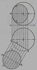
Section plane perpendicular to the H.P. And inclined to the V.P.:
Problem: The projections of a hemisphere 50 mm diameter, placed centrally on the top of a frustum of a hexagonal pyramid, base 32 mm side, top 20 mm side and axis 50 mm long are given. Draw the sectional front view when the vertical section plane H.T. Inclined at 45° to the V.P. And 10 mm from the axis, cuts them. Also draw the- true shapes of the sections of both the solids.

The widths of the section of the sphere at various points are obtained from the semi-circle drawn in the top view.
References:
1 Bhatt N.D., Panchal V.M. & Ingle P.R., (2014), Engineering Drawing, Charotar Publishing House
2 Shah, M.B. &Rana B.C. (2008), Engineering Drawing And Computer Graphics, Pearson Education
3 Agrawal B. & Agrawal C. M. (2012), Engineering Graphics, Tmh Publication
4 Narayana, K.L. & P Kannaiah (2008), Text Book On Engineering Drawing, Scitech publishers
5 (Corresponding Set Of) Cad Software Theory And User Manuals