UNIT 11
Television
Television means seeing at a distance. To be successful, a television system may be required to reproduce faithfully:
I. The shape of each object, or structural content
2. The relative brightness of each object, or tonal content
3. Motion, or kinematic content
4. Sound
5. Color, or chromatic content
6. Perspective, or stereoscopic content
Transmitter
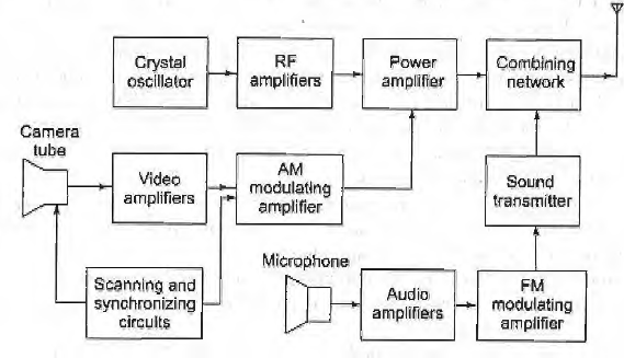
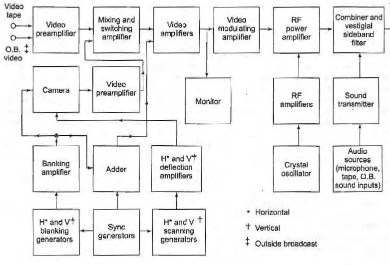
- The scene elements at the transmitting station are produced by a mosaic of photos within the camera tube, onto which the scene is foe-used by optical means.
- They are scanned by an electronic beam, whose intensity is modulated by the brightness of the scene.
- A varying voltage output is obtained which is proportional to the instantaneous brightness of each element.
- The varying voltage is amplified, impressed as modulation upon a VHF or UHF carrier, and radiated.
- If this beam is made to cover each element of the display screen area exactly in step with, the original scene will then be synthesized at the receiver.

Receiver
- The need for the receiver picture tube is exactly in step with that of the transmitter that requires appropriate information to be sent.
- This is synchronizing, i.e. transmiting m addition to the picture information.
- The two sets of signals are interleaved by time-division multiplex, and the picture carrier is amplitude-modulated by this total information.
- At the receiver, signals derived from the transmitted sync control the vertical and horizontal scanning circuits,hence ensuring that the receiver picture tube is in step with the transmitter camera tube.


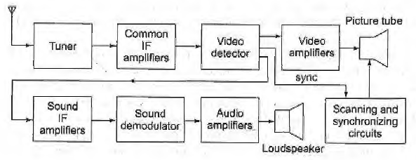
Here, in a typical black and white television receiver, the signal from the antenna is fed to the tuner.
Two channel selector switches – one for the VHF (very-high-frequency) and the other for the UHF (ultra-high-frequency) channels are used.
They connect circuits that are tuned to the desired channels and, also discriminate against signals from undesired channels.
These circuits also form part of an amplifier, then passed to the mixer, which transposes all the signal frequencies in the channel to different values, called intermediate frequencies.
The output of the tuner consists of all the signals in the desired channel.
The amplification is automatically adjusted, being maximum on a weak signal and less on a strong signal.
As far as the receiver handles the signals in the channel just like they would be received from the transmitter, except for the shift to intermediate frequencies and the amplification.
The next stage is the video detector, which removes the high frequency carrier signal and recovers the video signal.
The detector also reproduces (at a lower frequency) the sound carrier and its frequency variations. The sound signal is then separated from the picture signal and passes through a frequency detector, which recovers the audio signal.
This signal is amplified and fed to the loudspeaker.
The picture signal from the video detector is used in the normal fashion for display on the CRT of the television receiver.
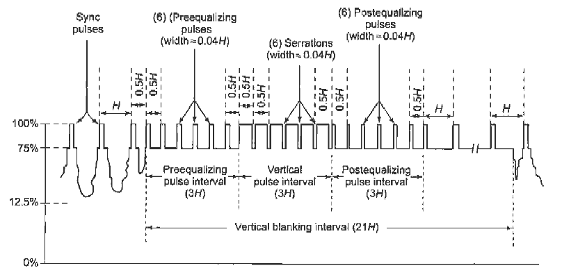
The first and more obvious shortcoming of the waveforms are examined after the start of the vertical blanking period, the leading edges of the three horizontal sync pulses and the vertical sync pulse which triggers the horizontal oscillator in the receiver.
There are no leading edges for a time of 3H, so the receiver horizontal oscillator either loses sync or stop oscillating, depending on the design.
The three leading edges are required during this 3H period.
The easiest way of providing is to cut slots in the vertical sync pulse.
The beginning of each slot has no effect, but the end of each provides the desired leading edge.
These slots are known as separations. They have widths of 0.04H each to ensure that they are visible.
At the end of an even field, separations 2, 4 and 6 or, to be precise, the leading edges are actually used to trigger the horizontal oscillator in the receiver.

The leading edges which occur midway through horizontal lines do no harm.
The edges are used either at the end of an even field or at the end of an odd one.
Those that are not used in a particular instance come at a time when they cannot trigger the horizontal waveform, and they are ignored.
The synchronization is obtained in the receiver from vertical sync pulses by integration.
The integrator produces a small output when it receives horizontal sync pulses, and a much larger output from vertical sync pulses, because their energy content is much higher.
The output level from the integrator eventually rises enough to cause triggering of the vertical oscillator in the receiver.
The equaliz ing pulses shown in the composite video waveform above.
References:
- Communication system by Bruce carison . TMH.
- Electronic Communication system by Kennedy IV Edition. TMH.
- Electronic Communication system by Roddey & Coolen, Pearson.
- Telecommunication system Engg. By Freeman John Wiley
- Communication system by Haykin,Wiley