UNIT 6
Analog pulse modulation
It is defined as the process of variation of amplitude of the pulse in accordance to the instantaneous variation in the message signal.
Let the message signal is given by,

A pulse train is a periodic signal and the information present in each period of the pulse train is given by,

Where, ∆ is the width of the pulse.
A PAM wave in time domain is obtained by multiplying the message signal with the pulse train given as,

Substituting p in the above equation we get,

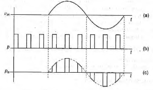
Fig.1 Generation of PAM signal (a) message (b) pulse train (c) PAM (ref 3)
The amplitude of PAM signal varies according to the message contour.
The spectrum of PAM has sinc function at all frequencies.
Demodulation:
- For Demodulation of PAM, PAM signal is fed to the low pass filter as shown in Figure.

PAM detector
- The low pass filter eliminates all the high frequency ripples and generates the demodulated signal whose amplitude is proportional to PAM signal at any instant of time.
- This signal is applied to an inverting amplifier and the demodulated output of almost equal amplitude is obtained with the modulating signal.
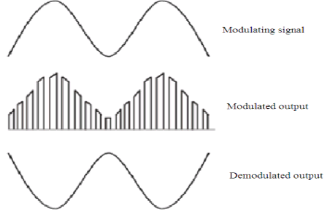
- Figure shows the modulated and demodulated PAM signal.
It is defined as the process of variation of width of the pulse in accordance to the instantaneous variation in the message signal.
Let ∆ be the width of the pulse then in PWM ,

Hence,

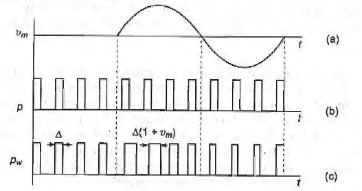
Fig.2 Generation of PWM signal (a) message (b) pulse train (c) PWM (ref 3)
When Vm = 0 then, ∆m = ∆
So when there is no message, the width of the pulse is equal to its original width.
When Vm is positive, then ∆m proportional to (1 + Vm)
When Vm is negative, then ∆m proportional to (1 - Vm)
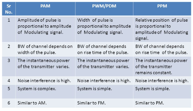
The amplitude of the pulse remains constant in PWM
Thus PWM is robust to noise as compared to PAM.
PWM have the spectrum in the baseband region . The illustration is given in Fig and is made only by using trailing edge of the pulse.
This can also be performed by using either leading edge or both.
The PWM signal also contains message information and is seldom used as a sampling process to discretize the continuous time signal.
Thus PWM has limited use in signal processing and communication field. Alternatively, PWM finds use in power applications like direct current (dc) motor speed control.
Demodulation:
- Here, a ramp ia added at the +ve edge which stops at the arrival of –ve egde.
- The ramp attains different heights in each cycle hence the widths are different and the heights attained are directly proportional to the pulse width and the amplitude of the message signal.
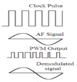
- This is passed through a low pass filter where it follows the envelop which produces the demodulated signal at the output.
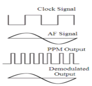
It is defined as the process of varying the position of the pulse in accordance to the instantaneous variation in the message signal.
Let timing instant of the pulse is proportional to its message then,

Mathematically, the position of leading or trailing edge is given by,

When there is no message, i.e. Vm = 0 then tp = 0.
When Vm is positive , tp = f(Vm)
When Vm is negative, - tp = - f(Vm) i.e. the position of the pulse will be shifted left.
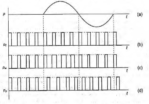
Fig.3 Generation of PPM signal (a) message (b) pulse train (c) PWM (d)PPM(ref 3)
If PWM is generated by varying the width of the trailing edge of the pulse then this edge will be extracted to get the position in each period.
Once the position is extracted, the leading or trailing edge of the pulse is placed at this instant. The amplitude and width of the pulse remain constant in the original pulse train.
Thus PPM is equally robust to noise like PWM.
However, the resulting PPM will also have the spectrum in the baseband region and if PWM is generated by varying the leading edge, then this edge needs to be extracted to generate PPM and any edge can be used in case of modification of both edges.
Even though, the PPM signal contains the message information it is seldom used due to store message. Information and also the randomness is involved in the position modification.
Thus PPM is of theoretical interest only and bas limited use in signal processing and communication field.
Demodulation:
- Here, ramp is used to start at the +ve edge of the one pulse and stops at the +ve edge of the next pulse.
- Thus the height of the obtained ramp is determined by the delay between the pulses which indirectly follows the amplitude of the modulating signal.
- This is then passed through a low pass filter which filters the envelop information as the demodulated signal.
References:
- Communication system by Bruce carison . TMH.
- Electronic Communication system by Kennedy IV Edition. TMH.
- Electronic Communication system by Roddey & Coolen, Pearson.
- Telecommunication system Engg. By Freeman John Wiley
- Communication system by Haykin,Wiley