The source code is called a programme written in a high-level language. Translators are needed to convert the source code into machine code.
A translator takes an input programme written in the source language and transforms it into an output programme in the target language.
The error is also identified and reported during translation.
Role of translator
● The high-level language programme input is translated into an equivalent machine language programme.
● Providing diagnostic messages wherever the programmer breaches high-level language programme specifications.
Language translator is a programme that is used to convert instructions into object code, i.e. from high-level language or assembly language to machine language, written in the source code.
There are 3 types of translators for languages. There are:
- Compilers
A converter is a translator used to translate the programming language of the high level to the programming language of the low level. In one session, it converts the entire programme and records errors found during the conversion. The compiler needs time to do its job by converting high-level code all at once into lower-level code and then saving it to memory.
A compiler is processor-based and dependent on the platform. But a special compiler, a cross-compiler and a source-to-source compiler have discussed it. Users must first define the Instruction Set Architecture (ISA), the operating system (OS), and the programming language to be used to ensure that it is compatible, before selecting a compiler.
2. Interpreter
A translator is used to translate a high-level programming language to a low-level programming language, much like a compiler. It converts the programme one at a time and, when doing the conversion, records errors found at once. Through this, errors can be found more quickly than in a compiler.
It is also used as a software development debugging tool, as it can execute a single line of code at a time. An interpreter is therefore more versatile than a compiler, since you can operate between hardware architectures because it is not processor-dependent.
3. Assembler
An assembler is a translator used to transform the language of the assembly into the language of the machine. It is like an assembly language compiler, just like an interpreter, it is interactive. It is hard to understand the assembly language because it is a low-level programming language. A low-level language, an assembly language, is converted by an assembler into an even lower-level language, which is machine code. The computer code can be interpreted by the CPU directly.
Key takeaway:
● The source code is called a programme written in a high-level language.
● Translators are needed to convert the source code into machine code.
● Language translator is a programme that is used to convert instructions into object code, i.e. from high-level language or assembly language to machine language, written in the source code.
Intermediate representation in three ways:
- Syntax tree
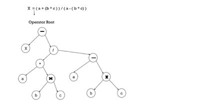
The syntax tree is nothing more than a condensed parse tree shape. The parse tree operator and keyword nodes are transferred to their parents, and in the syntax tree the internal nodes are operators and child nodes are operands, a chain of single productions is replaced by a single connection. Put parentheses in the expression to shape the syntax tree, so it is simple to identify which operand should come first.
Example –
x = (a + b * c) / (a – b * c )
|
Fig 1: syntax tree
2. Postfix notation
The standard way to write the sum of a and b is with the operator in the middle: a + b
For the same expression, the postfix notation positions the operator as ab + at the right end. In general, the consequence of adding + to the values denoted by e1 and e2 is postfix notation by e1e2 +, if e1 and e2 are any postfix expressions, and + is any binary operator.
In postfix notation, no parentheses are needed because the location and arity (number of arguments) of the operators enable only one way of decoding a postfix expression. The operator obeys the operand in postfix notation.
Example –
Representation of a phrase by postfix (a – b) * (c + d) + (e – f) is :
ab – cd + *ef -+.
3. Three address code
Three address statements are defined as a sentence that contains no more than three references (two for operands and one for outcomes). Three address codes are defined as a series of three address statements. The type x = y op z is a three address statement, where x, y, z would have an address (memory location). A statement may often contain fewer than three references, but it is still considered a statement of three addresses.
Example –
The code of the three addresses for the phrase : a + b * c + d :
T 1 = b * c
T 2 = a + T 1
T 3 = T 2 + d
T 1, T 2, T 3 are temporary variables .
Advantages of three address code
● For target code generation and optimization, the unravelling of complex arithmetic expressions and statements makes the three-address code ideal.
● Using names for the intermediate values determined by a programme makes it easy to rearrange the three-address code - unlike postfix notation.
Key takeaway:
● The syntax tree is nothing more than a condensed parse tree shape.
● In postfix notation, no parentheses are needed because the location and arity of the operators enable only one way of decoding a postfix expression.
● Three address statements are defined as a sentence that contains no more than three references.
Simply put, with the least effort, the best programme improvements are those that yield the most benefit. There should be several properties for the transformations given by the optimizing compiler.
There are:
- The transition must retain the importance of programmes. In other words, the optimization must not modify the output generated by the programme for a given input, or cause an error that was not present in the original source programme, such as division by zero.
2. On average, a transition must speed up programmes by a measurable amount. While the size of the code has less value than it once did, we are still interested in reducing the size of the compiled code. Not every improvement succeeds in improving every programme, a "optimization" can also slow down a programme slightly.
3. The effort must be worth the transformation. It does not make sense for a compiler writer to spend the intellectual effort to introduce a transformation enhancing code and have the compiler spend the extra time compiling source programmes if this effort is not repaid when the target programmes are executed."Peephole" transformations of this kind are easy and useful enough to be included in any compiler.
|
Fig 2: Organization of the code optimizer
Control flow
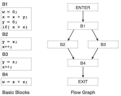
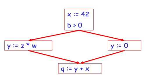
A flow graph is a directed graph with information for flow control applied to the basic blocks.
● By means of control flow graphs, basic blocks in a programme can be represented.
● A control flow graph shows how the software control is transferred between the blocks.
● It is a helpful tool that helps to optimise the software by helping to find any unnecessary loops.
|
Fig 3: Control flow
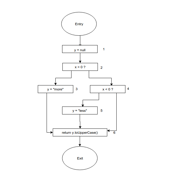
Control Flow Analysis (CFA) Static analysis tool for discovering the hierarchical control flow within a procedure (function).
Examination within a programme or process of all potential execution routes.
Represents the procedure's control structure using Control Flow Diagrams.
Key takeaway:
● optimization must not modify the output generated by the programme for a given input, or cause an error that was not present in the original source programme, such as division by zero.
● A flow graph is a directed graph with information for flow control applied to the basic blocks.
● Control Flow Analysis Static analysis tool for discovering the hierarchical control flow within a function.
It is the data flow analysis in the control flow graph, i.e. the analysis, which determines the information in the programme for the definition and use of data. Optimization can be done with the assistance of this analysis. In general, the method in which data flow analysis is used to compute values. The data flow property represents information that can be used for optimization.
A specific data-flow meaning is a set of definitions and we want to equate the same set of definitions that can hit that point with each point in the programme. The choice of abstraction, as discussed above, depends on the purpose of the analysis; to be effective, we only keep track of relevant details.
Before and after each sentence, the data-flow values are denoted by IN[S] and OUT[s], respectively. For all statements s, the data-flow issue is to find a solution to a set of limitations on the IN[S]'S and OUT[s ]'s. Two sets of restrictions exist: those based on the statements' semantics ('transfer functions') and those based on the control flow.
Transfer Functions
|
Fig 4: example of data flow analysis
Data flow Properties
● Available Expression : An expression is said to be accessible along paths reaching x at a programme point x if. At its evaluation level, an expression is available. If none of the operands are changed prior to their use, an expression a+b is said to be available.
Pros : It is used to exclude sub expressions that are common.
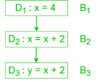
● Reaching Definition : If there is a path from D to x in which D is not destroyed, i.e. not redefined, then the meaning D reaches point x.
Pros : It's used in the propagation of constants and variables.
|
Fig 5: reaching definition
D is reaching definition for B2 but not for B3 since it is killed by D2.
● Live Variable : If the variable is used from p to end until it is redefined else it becomes dead, a variable is said to be live at some stage p.
Pros : It is useful for assigning registers.
It is used in the removal of dead codes.
● Busy Expression : An expression is busy along a path if its assessment occurs along that path and none of its operand meaning exists along the path before its assessment.
Pros : It is used to perform optimization of code movement.
Key takeaway:
● It is the data flow analysis in the control flow graph, i.e. the analysis, which determines the information in the programme for the definition and use of data.
● A specific data-flow meaning is a set of definitions and we want to equate the same set of definitions that can hit that point with each point in the programme.
Transformations are applied to tiny blocks of sentences. Before global optimization, local optimization is completed.
Optimization is carried out within a fundamental block.
The simplest type of optimization The entire procedure body does not need to be analyzed-only the basic blocks The local optimization techniques include:
● Constant Folding
● Constant Propagation
● Algebraic Simplification and Reassociation
● Operator Strength Reduction
● Copy Propagation
● Dead Code Elimination code optimization
Constant folding
● Evaluation of compile-time expressions whose operands are recognised as constants
If an expression such as 10 + 2 * 3 is encountered, the compiler will calculate the result as (16) at compile time and thus substitute the value for the expression.
A conditional branch such as if a < b goto L1 otherwise goto L2 where a and b are constants can be substituted by an optimization of goto L1 or goto L2 code.
Constant propagation
● If a variable is given a constant value, it is possible to substitute the constant for subsequent uses of that variable.
For example :
temp4 = 0;
f0 = temp4; f0 = 0;
temp5 = 1; can be converted as code optimization f1 = 1;
f1 = temp5; i = 2;
temp6 = 2;
i = temp6;
Algebraic simplification and reassociation
● Algebraic properties or operand-operator combinations are used for simplification.
● Re-association refers to rearranging an expression by using properties such as associativity, commutativity, and distributivity.
X + 0 = X
0 + X = X e.g. :- b = 5 + a +10;
X * 1 = X temp0 = 5; temp0 = 15;
1 * X = X temp1 = temp0+a; temp1 =a+temp0;
0 / X = 0 temp2 = temp1 + 10; b = temp1;
X – 0 = X b = temp2;
b && true = true
b && false = false
Operator strength reduction
● Replace an operator with a less costly one.
e.g.:-
i * 2 = 2 * i = i + i
i / 2 = (int) (i * 0.5)
0 – i = - i
f * 2 = 2.0 * f = f + f
f/0.2 = f * 0.5
Where, f – floating point number, i = integer
Copy propagation
● Similar to constant propagation, but extended to values which are not constant.
Example :-
temp2 = temp1; temp3 = temp1 * temp1;
temp3 = temp2 * temp1; temp5 = temp3 * temp1;
temp4 = temp3; c = temp5 +temp3;
temp5 = temp3 *temp2;
c = temp5 +temp4;
Dead code elimination
● If the outcome of an instruction is never used, the instruction is considered "dead" and can be eliminated.
Example : Remember the temp1 = temp2 + temp3 argument, and we can delete it if temp1 is never used again.
Key takeaway:
● Transformations are applied to tiny blocks of sentences. Before global optimization, local optimization is completed.
● Optimization is carried out within a fundamental block.
● Transformations are applied to broad portions of the software, which include elements, procedures and loops.
● Optimization through fundamental blocks.
● To perform optimization across simple blocks, data-flow analysis is performed.
● In the program's flow graph, each basic block is a node.
● It is possible to apply these optimisations to an entire control-flow graph.
● An expression is specified at the point where a value is assigned and then killed.
|
Fig 6: control graph
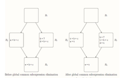
implement common sub-expression elimination
When a new value is subsequently assigned to one of its operands.
If each path leading to p includes a prior description of that expression that is not subsequently destroyed, an expression is available at some point p in a flow graph.
avail[B] = set of expressions available on entry to block B
exit[B] = set of expressions available on exit from B
killed[B] = set of expressions killed in B
defined[B] = set of expressions defined in B
exit[B] = avail[B] – killed[B] + defined[B]
Algorithm for global common subexpression elimination
- First, for each basic block, measure identified and killed sets.
- The entry and exit sets for each block are computed iteratively by running the following algorithm until a stable fixed point is reached:
A) Identify in some block B any statement s of the form a = b op c such that b op c is available at the entry to B and neither b nor c is redefined before s in B.
B) In the graph, follow the backward flow of control passing back to but not through each block that determines b op c. In such a block, the last computation of b op. c reaches s.
C) Add statement t = d to the block where t is a new temp after each computation d = b op c defined in step 2a.
D) Substitute a = t for s
|
Fig 7: example of global common subexpression elimination
Key takeaway:
● Transformations are applied to broad portions of the software, which include elements, procedures and loops.
● To perform optimization across simple blocks, data-flow analysis is performed.
Loop optimization is the most useful machine-independent optimization since the inner loop of the software requires a programmer's time in bulk.
When we reduce the number of instructions in an inner loop, even though we increase the amount of code outside that loop, the running time of a programme can be increased.
The following three techniques are critical for loop optimization:
- Code motion
To minimise the amount of code in the loop, code movement is used. This transition involves a statement or expression that can be transferred beyond the body of the loop without affecting the program's semantics.
Example :
The limit-2 equation is a loop invariant equation in the sense argument.
while (i<=limit-2) /*statement does not change limit*/
After code motion the result is as follows:
a= limit-2;
while(i<=a) /*statement does not change limit or a*/
2. Induction-variable elimination
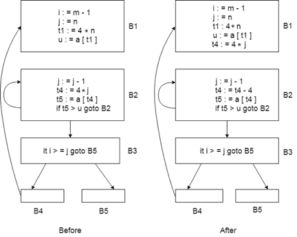
To substitute the variable from the inner loop, induction variable removal is used.
In a loop, it may reduce the number of additions. It enhances the efficiency of both code space and run time.
|
Fig 8: shows before and after condition
We can replace the assignment t4:=4*j in this figure with t4:=t4-4. The only issue that will occur is that when we first join block B2, t4 does not have a meaning. So we put a t4=4*j relationship on the B2 block entry.
3. Strength reduction
● Strength reduction is used to substitute the cheaper one on the goal computer for the costly process.
● It is easier to add a constant than a multiplication. So, inside the loop, we can substitute multiplication with an addition.
● It is easier for multiplication than exponentiation. So we can substitute multiplication inside the loop with exponentiation.
Example :
while (i<10)
{
j= 3 * i+1;
a[j]=a[j]-2;
i=i+2;
}
The code would be, after strength reduction:
s= 3*i+1;
while (i<10)
{
j=s;
a[j]= a[j]-2;
i=i+2;
s=s+6;
}
It is easier to compute s=s+6 in the above code than j=3 *i
Key takeaway :
● To substitute the variable from the inner loop, induction variable removal is used.
● To minimise the amount of code in the loop, code movement is used.
● Loop optimization is the most useful machine-independent optimization.
A code-generation statement-by-statement strategy also generates target code containing redundant instructions and sub-optimal constructs. It is possible to boost the consistency of such a target code by adding "optimising" transformations to the target programme.
Peephole optimization, a method for trying to improve the performance of the target programme by analysing a short series of target instructions (called the peephole) and replacing these instructions, wherever possible, with a shorter or faster sequence, is an easy but successful technique for improving the target code.
A small, moving window on the target programme is the peephole. The code in the peephole does not need to be contiguous, though this is needed by some implementations. It is typical of peephole optimization that additional improvements can be generated by each enhancement.
A bunch of statements are evaluated and the following potential optimization is checked:
1. Redundant instruction elimination
The following can be performed by the user at the source code level:
|
The compiler looks for instructions at the compilation stage that are redundant in nature. Even if some of them are omitted, multiple loading and storing instructions can carry the same significance.
For instance:
● MOV x, R0
● MOV R0, R1
The first instruction can be omitted and the sentence re-written as
MOV x, R1
2. Unreachable
Unreachable code is a portion of the programme code that, because of programming constructs, is never accessed. Programmers may have written a piece of code unintentionally that can never be reached.
Example :
void add_ten(int x)
{
return x + 10;
printf(“value of x is %d”, x);
}
3. Flow of control optimization
There are occasions in a code where, without performing any significant task, the programme control bounces back and forth. It is possible to delete these hops.
Find the following code chunk:
...
MOV R1, R2
GOTO L1
...
L1 : GOTO L2
L2 : INC R1
4. Algebraic expression simplification
There are times when it is possible to make algebraic expressions simple. For instance, it is possible to replace the expression a = a + 0 with an expression itself, and the expression a = a + 1 may simply be replaced with INC a.
Key takeaway :
● A code-generation statement-by-statement strategy also generates target code containing redundant instructions and sub-optimal constructs.
● A small, moving window on the target programme is the peephole.
● Peephole optimization, a method for trying to improve the performance of the target programme by analysing a short series of target instructions (called the peephole).
● Reordering of instructions in order to keep the working unit pipelines complete with no stalls.
● NP-Full and includes heuristics.
● Used on fundamental blocks (local).
● Global scheduling allows simple blocks to be elongated (super-blocks).
● Instruction scheduling is a compiler optimization used to enhance parallelism at the instruction level that enhances performance on instruction pipeline machines. Put more clearly, without modifying the context of the code, it attempts to do the following:
○ In rearranging the order of instructions, stop pipeline stalls.
○ Avoid unlawful activities or semantically vague ones (typically involving subtle instruction pipeline timing issues or non-interlocked resources).
Structural hazards (processor resource limit), data hazards (output of one instruction required by another instruction) and control hazards may be caused by pipeline stalls (branching).
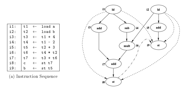
Dependence DAG
Full line: flow dependence, dash line: dash-dot line of anti-dependency: performance dependence.
Some non- and performance dependencies are because it could not be done to disambiguate memory.
|
Fig 9: Instruction sequence and DAG
Basic Block Scheduling
● Micro-operation sequences (MOS), which are indivisible, form the basic block.
● There are several phases in each MOS, each needing money.
● For execution, each stage of a MOS requires one cycle.
● The proposed programme must satisfy precedence constraints and resource constraints.
○ PC's apply to data dependencies and delays in execution.
○ RC's are linked to restricted shared resources availability.
Automaton-based Scheduling
● Constructs a collision automaton indicating whether it is legal in a given period to issue an instruction (i.e., no resource contentions).
● The collision automaton understands sequences of legal instructions.
● Avoids comprehensive searching involved in the scheduling of a list.
● To handle precedence constraints, it uses the same topological ordering and ready queue as in list scheduling.
● You can create Automaton offline using resource reservation tables.
Superblock and Hyperblock scheduling
A Superblock is a road with no side entrances
● Only from the top, Control can enter
● Several exits are probable.
● Eliminates most overheads for book-keeping
Formation of Superblock
● Shape of traces as before
● To stop side entrances into a superblock, tail duplication
● Increases in code size
Hyperblock scheduling
● With control-intensive programmes that have multiple control flow paths, Superblock scheduling does not work well.
● To manage such programmes, Hyperblock scheduling was proposed.
● To exclude conditional branches, the control flow graph is IF-converted here.
● IF-conversion replaces conditional branches with predicated instructions that are suitable.
● Control dependency is now converted into a reliance on data.
Key takeaway:
● Instruction scheduling is a compiler optimization used to enhance parallelism at the instruction level that enhances performance on instruction pipeline machines.
● Reordering of instructions in order to keep the working unit pipelines complete with no stalls.
Loop Optimization is the process of increasing execution speed and lowering the loop-related overheads. It plays an important role in improving cache performance and making efficient use of the capabilities of parallel processing. Most of a scientific program's execution time is spent on loops.
Even if the amount of code outside that loop is increased, decreasing the number of instructions in an internal loop improves a program's running time.
The changes can enhance the loop cache location traversal or allowing other optimizations that were previously impossible owing to poor data dependencies. It is possible to use these loop transforms in a very flexible way, and repeatedly used until the dependencies of the loop are the memory layout and cache effects are optimal and are well aligned.
Loop optimization technique:
- Frequency Reduction
The amount of code in the loop is reduced by frequency reduction. A declaration or expression that can be moved outside the body of the loop without affecting the program's semantics is moved outside the loop.
2. Loop Unrolling
Loop unrolling is a technique for loop transformation that helps to optimise a program's execution time. We basically remove iterations or decrease them. By eliminating loop control instructions and loop test instructions, loop unrolling increases the program's speed.
3. Loop Jamming
Loop jamming is the combination of a single loop with two or more loops. This reduces the time it takes to compile a lot of loops.
Key takeaway:
● Loop Optimization is an optimization independent of the machine.
● The changes can enhance the loop cache location traversal or allowing other optimizations that were previously impossible owing to poor data dependencies.
The quickest positions in the hierarchy of memory are registers. But this resource is, unfortunately, small. It falls under the target processor's most restricted tools. Allocation of the register is an NP-complete problem. However, to achieve allocation and assignment, this issue can be reduced to graph colouring. An effective approximate solution to a difficult problem is therefore calculated by a good register allocator.
The allocator of the register specifies the values that will reside in the register and the register that will contain each of those values. It takes a programme with an arbitrary number of registers as its input and generates a programme that can fit into the target machine with a finite register set.
Allocation Vs Assignment
Allocation
Map an infinite namespace to the target machine's register set.
● Reg. to reg. Model : Digital records are mapped to actual registers, but excess memory spills out.
● Mem. to mem. Model : Maps any memory location sub-set to a set of names that models the set of physical registers.
Allocation ensures that the code matches the register of the target computer. Put on each instruction.
Assignment
Maps the assigned name set to the target machine physical register set.
● Assumes that the allocation was performed so that the code fits into the physical register set.
● In the registers, no more than 'k' values are specified, where 'k' is the number of physical registers.
Target code generation
The final step of the compiler is target code generation.
Input: Intermediate Representation Optimized.
Output: Target Code.
Job Performed: Register methods for allocation and optimization, code for assembly stage.
Method: Three common register allocation and optimization strategies.
Implement: Algorithms.
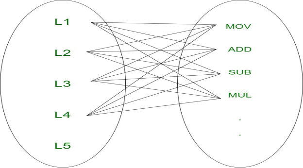
Goal code generation deals with the language of assembly to translate optimised code into an understandable format for the computer. Machine readable code or assembly code may be the target code. Each line can map to one or more lines in the computer (or) assembly code in optimised code, so they are associated with a 1:N mapping.
|
Fig 10: 1:N mapping
Computations, known as registers, are typically believed to be done on high-speed memory locations. It is efficient to perform different operations on registers, as registers are faster than cache memory. This function is used effectively by compilers, but registers are not available in large quantities and are expensive. We should also aim to use the minimum number of records to incur low total costs.
Key takeaway:
● The quickest positions in the hierarchy of memory are registers.
● The final step of the compiler is target code generation.
● The allocator of the register specifies the values that will reside in the register and the register that will contain each of those values.
References:
- CompilersPrinciples.Techniques.AndToolsbyAlfredV.Aho.RaviSethiJefferyD.Ullman.PearsonEducation.
- Modern Compiler Design by Dick Grune . E. Bal. Ceriel J. H. Jacobs. And Koen G. Langendoen Viley Dreamtech.
- https://www.slideshare.net
- https://www.geeksforgeeks.org
