UNIT-1
Data Communication Components
Computer does not understand human language. Any data, viz., letters, symbols, pictures, audio, videos, etc., fed to computer should be converted to machine language first. Computers represent data in the following three forms − We are introduced to concept of numbers from a very early age. To a computer, everything is a number, i.e., alphabets, pictures, sounds, etc., are numbers. Number system is categorized into four types −
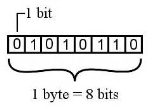
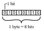
Bits − A bit is a smallest possible unit of data that a computer can recognize or use. Computer usually uses bits in groups. Bytes − group of eight bits is called a byte. Half a byte is called a nibble.
The following table shows conversion of Bits and Bytes –
Text code is format used commonly to represent alphabets, punctuation marks and other symbols. Four most popular text code systems are −
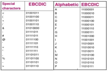
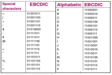
Extended Binary Coded Decimal Interchange Code is an 8-bit code that defines 256 symbols. Given below is the EBCDIC Tabular column
Fig 1 - EBCDIC Tabular column American Standard Code for Information Interchange is an 8-bit code that specifies character values from 0 to 127. ASCII Tabular column
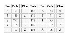
Extended American Standard Code for Information Interchange is an 8-bit code that specifies character values from 128 to 255. Extended ASCII Tabular column
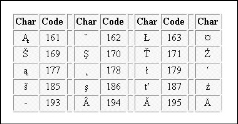
Fig 2 - Extended ASCII Tabular column Unicode Worldwide Character Standard uses 4 to 32 bits to represent letters, numbers and symbol. Unicode Tabular Column
Fig 3 - Unicode Tabular Column
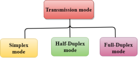
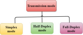
The Transmission mode is divided into three categories:
Fig 4 – Transmission mode types
Fig 5 – Simplex mode
Fig 6 – Half Duplex mode
Advantage of Half-duplex mode:
Disadvantage of Half-Duplex mode:
Fig 7 – Full duplex mode
Advantage of Full-duplex mode:
Disadvantage of Full-duplex mode:
Differences b/w Simplex, Half-duplex and Full-duplex mode
| ||||||||||||||||||||||||||||||||||||||||||||||||||||||||||||||||||||||||||||||||||||||||||||||||||
Key takeaways
Computer does not understand human language. Any data, viz., letters, symbols, pictures, audio, videos, etc., fed to computer should be converted to machine language first. Computers represent data in the following three forms –
2. Number System
We are introduced to concept of numbers from a very early age. To a computer, everything is a number, i.e., alphabets, pictures, sounds, etc., are numbers. Number system is categorized into four types –
- Binary number system consists of only two values, either 0 or 1
- Octal number system represents values in 8 digits.
- Decimal number system represents values in 10 digits.
- Hexadecimal number system represents values in 16 digits.
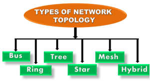
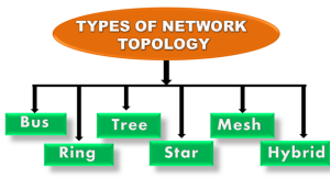
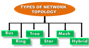
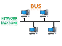
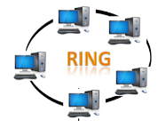
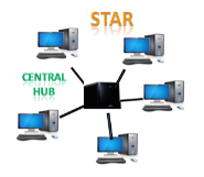
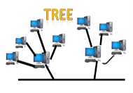
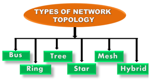
Topology defines the structure of the network of how all the components are interconnected to each other. There are two types of topology: physical and logical topology. Physical topology is the geometric representation of all the nodes in a network.
Fig 8 – Types of network topology
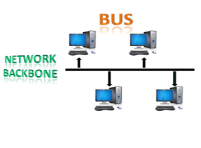
Fig 9 – Bus topology
CSMA: It is a media access control used to control the data flow so that data integrity is maintained, i.e., the packets do not get lost. There are two alternative ways of handling the problems that occur when two nodes send the messages simultaneously.
Disadvantages of Bus topology:
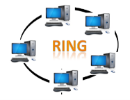
Fig 10 – Ring topology
Disadvantages of Ring topology:
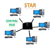
Fig 11 – Star topology
Disadvantages of Star topology
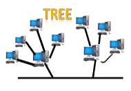
Fig 12 – Tree topology
Disadvantages of Tree topology
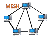
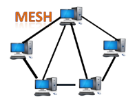
Fig 13 – Mesh topology
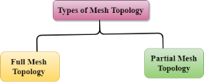
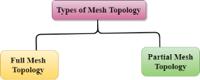
Where n is the number of nodes that represents the network. Mesh topology is divided into two categories:
Fig 14 – Types of mesh topology
Reliable: The mesh topology networks are very reliable as if any link breakdown will not affect the communication between connected computers. Fast Communication: Communication is very fast between the nodes. Easier Reconfiguration: Adding new devices would not disrupt the communication between other devices.
Disadvantages of Mesh topology
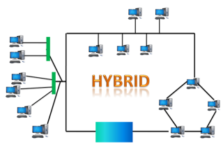
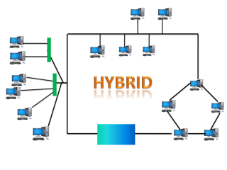
Fig 15 – Hybrid topology
Disadvantages of Hybrid topology
|
Key takeaways
|
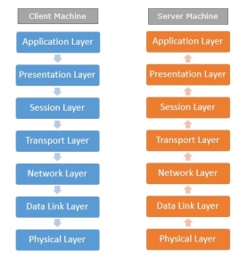
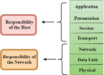
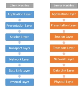
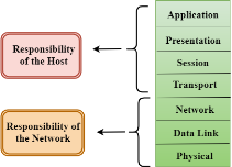
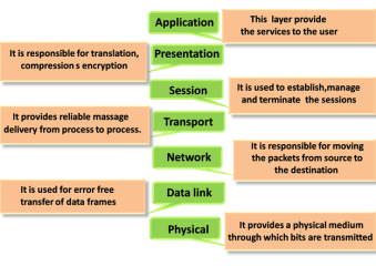
Network Protocols are a set of rules governing exchange of information in an easy, reliable and secure way. Before we discuss the most common protocols used to transmit and receive data over a network, we need to understand how a network is logically organized or designed. The most popular model used to establish open communication between two systems is the Open Systems Interface (OSI) model proposed by ISO. OSI model is not a network architecture because it does not specify the exact services and protocols for each layer. It simply tells what each layer should do by defining its input and output data. It is up to network architects to implement the layers according to their needs and resources available. These are the seven layers of the OSI model −
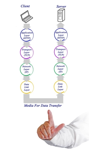
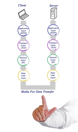
Fig 16 – Client server machine It is not necessary for every network to have all the layers. For example, network layer is not there in broadcast networks. When a system wants to share data with another workstation or send a request over the network, it is received by the application layer. Data then proceeds to lower layers after processing till it reaches the physical layer. At the physical layer, the data is actually transferred and received by the physical layer of the destination workstation. There, the data proceeds to upper layers after processing till it reaches application layer. At the application layer, data or request is shared with the workstation. So each layer has opposite functions for source and destination workstations. For example, data link layer of the source workstation adds start and stop flags to the frames but the same layer of the destination workstation will remove the start and stop flags from the frames. Let us now see some of the protocols used by different layers to accomplish user requests. TCP/IP stands for Transmission Control Protocol/Internet Protocol. TCP/IP is a set of layered protocols used for communication over the Internet. The communication model of this suite is client-server model. A computer that sends a request is the client and a computer to which the request is sent is the server.
Fig 17 – Media for data transfer TCP/IP has four layers −
TCP/IP is widely used in many communication networks other than the Internet.
As we have seen, the need for network came up primarily to facilitate sharing of files between researchers. And to this day, file transfer remains one of the most used facilities. The protocol that handles these requests is File Transfer Protocol or FTP.
Fig 18 - FTP Using FTP to transfer files is helpful in these ways −
Point to Point Protocol or PPP is a data link layer protocol that enables transmission of TCP/IP traffic over serial connection, like telephone line.
Fig 19 - PPP To do this, PPP defines these three things −
Using PPP, home users can avail Internet connection over telephone lines. |
Key takeaways
- Network Protocols are a set of rules governing exchange of information in an easy, reliable and secure way. Before we discuss the most common protocols used to transmit and receive data over a network, we need to understand how a network is logically organized or designed. The most popular model used to establish open communication between two systems is the Open Systems Interface (OSI) model proposed by ISO.
- OSI model is not a network architecture because it does not specify the exact services and protocols for each layer. It simply tells what each layer should do by defining its input and output data. It is up to network architects to implement the layers according to their needs and resources available.
Fig 20 - Characteristics of OSI Model
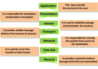
There are the seven OSI layers. Each layer has different functions. A list of seven layers are given below:
Fig 21 – Layers of OSI model
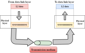
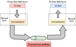
Fig 22 – Transmission medium
Functions of a Physical layer:
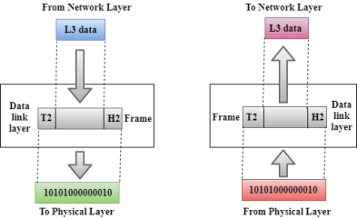
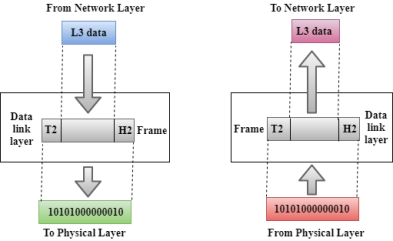
Fig 23 – Data link layer
Functions of the Data-link layer
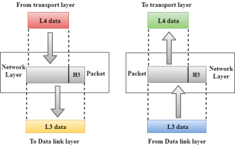
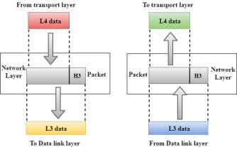
Fig 24 – Network layer
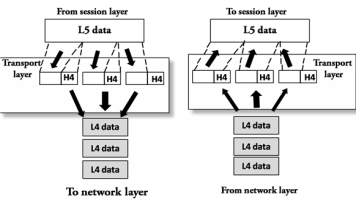
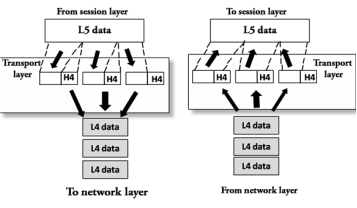
Fig 25 – Transport layer
The two protocols used in this layer are:
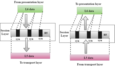
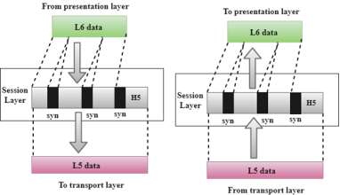
Fig 26 – Session layer
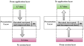
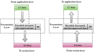
Fig 27 – Presentation layer
Functions of Presentation layer:
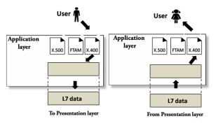
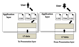
Fig 28 – Application layer
Functions of Application layer:
|
Key takeaways
- OSI stands for Open System Interconnection is a reference model that describes how information from a software application in one computer moves through a physical medium to the software application in another computer.
- OSI consists of seven layers, and each layer performs a particular network function.
- OSI model was developed by the International Organization for Standardization (ISO) in 1984, and it is now considered as an architectural model for the inter-computer communications.
- OSI model divides the whole task into seven smaller and manageable tasks. Each layer is assigned a particular task.
- Each layer is self-contained, so that task assigned to each layer can be performed independently.
Some factors need to be considered for designing the transmission media:
Causes Of Transmission Impairment:
Fig 29 – Transmission Impairment
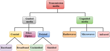
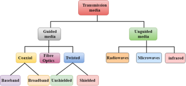
Classification Of Transmission Media:
Fig 30 – Classification of transmission media
It is defined as the physical medium through which the signals are transmitted. It is also known as Bounded media. Types Of Guided media: Twisted pair is a physical media made up of a pair of cables twisted with each other. A twisted pair cable is cheap as compared to other transmission media. Installation of the twisted pair cable is easy, and it is a lightweight cable. The frequency range for twisted pair cable is from 0 to 3.5KHz. A twisted pair consists of two insulated copper wires arranged in a regular spiral pattern. The degree of reduction in noise interference is determined by the number of turns per foot. Increasing the number of turns per foot decreases noise interference.
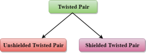
Fig 31 – Twisted pair Types of Twisted pair:
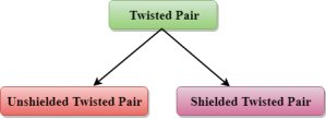
Fig 32 – Types of twisted pair An unshielded twisted pair is widely used in telecommunication. Following are the categories of the unshielded twisted pair cable:
Advantages Of Unshielded Twisted Pair:
Disadvantage:
A shielded twisted pair is a cable that contains the mesh surrounding the wire that allows the higher transmission rate. Characteristics Of Shielded Twisted Pair:
Disadvantages
Fig 33 – Coaxial cable Coaxial cable is of two types:
Advantages Of Coaxial cable:
Disadvantages Of Coaxial cable:
Diagrammatic representation of fibre optic cable:
Fig 34 – Fibre optic cable Basic elements of Fibre optic cable:
Following are the advantages of fibre optic cable over copper:
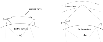
Unguided transmission is broadly classified into three categories:
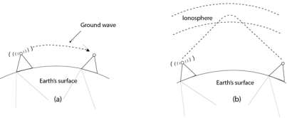
Fig 35 – FM radio Applications Of Radio waves:
Advantages Of Radio transmission:
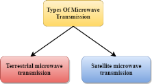
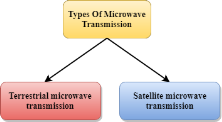
Fig 36 – Types of microwave transmission Microwaves are of two types:
Terrestrial Microwave Transmission
Characteristics of Microwave:
Advantages Of Microwave:
Disadvantages of Microwave transmission:
Satellite Microwave Communication
How Does Satellite work? The satellite accepts the signal that is transmitted from the earth station, and it amplifies the signal. The amplified signal is retransmitted to another earth station. Advantages Of Satellite Microwave Communication:
Disadvantages Of Satellite Microwave Communication:
Characteristics Of Infrared:
|
Key takeaways
- Transmission media is a communication channel that carries the information from the sender to the receiver. Data is transmitted through the electromagnetic signals.
- The main functionality of the transmission media is to carry the information in the form of bits through LAN(Local Area Network).
- It is a physical path between transmitter and receiver in data communication.
- In a copper-based network, the bits in the form of electrical signals.
- In a fibre based network, the bits in the form of light pulses.
- In OSI(Open System Interconnection) phase, transmission media supports the Layer 1. Therefore, it is considered to be as a Layer 1 component.
- The electrical signals can be sent through the copper wire, fibre optics, atmosphere, water, and vacuum.
- The characteristics and quality of data transmission are determined by the characteristics of medium and signal.
- Transmission media is of two types are wired media and wireless media. In wired media, medium characteristics are more important whereas, in wireless media, signal characteristics are more important.
- Different transmission media have different properties such as bandwidth, delay, cost and ease of installation and maintenance.
- The transmission media is available in the lowest layer of the OSI reference model, i.e., Physical layer.
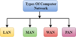
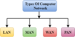
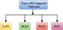
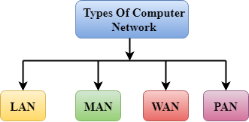
A computer network is a group of computers linked to each other that enables the computer to communicate with another computer and share their resources, data, and applications. A computer network can be categorized by their size. A computer network is mainly of four types:
Fig 37 – Types of computer network
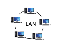
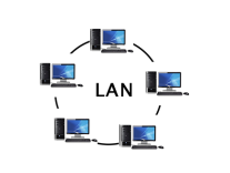
Fig 38 - LAN
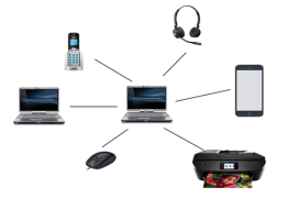
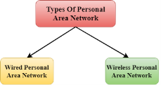
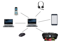
Fig 39 - PAN There are two types of Personal Area Network:
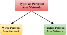
Fig 40 – Types of PAN
Wireless Personal Area Network: Wireless Personal Area Network is developed by simply using wireless technologies such as WiFi, Bluetooth. It is a low range network. Wired Personal Area Network: Wired Personal Area Network is created by using the USB. Examples Of Personal Area Network:
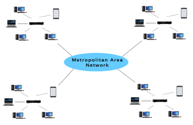
MAN(Metropolitan Area Network)
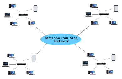
Fig 41 - MAN Uses Of Metropolitan Area Network:
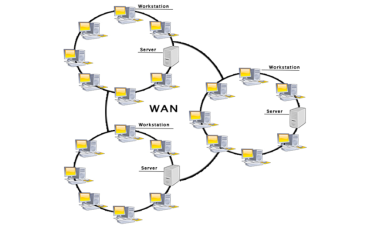
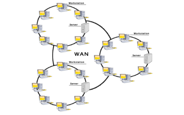
Fig 42 - WAN Examples Of Wide Area Network:
Advantages Of Wide Area Network: Following are the advantages of the Wide Area Network:
Disadvantages of Wide Area Network: The following are the disadvantages of the Wide Area Network:
1. Extranet: An extranet is a communication network based on the internet protocol such as Transmission Control protocol and internet protocol. It is used for information sharing. The access to the extranet is restricted to only those users who have login credentials. An extranet is the lowest level of internetworking. It can be categorized as MAN, WAN or other computer networks. An extranet cannot have a single LAN, atleast it must have one connection to the external network. 2. Intranet: An intranet is a private network based on the internet protocol such as Transmission Control protocol and internet protocol. An intranet belongs to an organization which is only accessible by the organization's employee or members. The main aim of the intranet is to share the information and resources among the organization employees. An intranet provides the facility to work in groups and for teleconferences.
Wireless LAN stands for Wireless Local Area Network. It is also called LAWN (Local Area Wireless Network). WLAN is one in which a mobile user can connect to a Local Area Network (LAN) through a wireless connection. The IEEE 802.11 group of standards defines the technologies for wireless LANs. For path sharing, 802.11 standard uses the Ethernet protocol and CSMA/CA (carrier sense multiple access with collision avoidance). It also uses an encryption method i.e. wired equivalent privacy algorithm. Wireless LANs provide high speed data communication in small areas such as building or an office. WLANs allow users to move around in a confined area while they are still connected to the network. In some instance wireless LAN technology is used to save costs and avoid laying cable, while in other cases, it is the only option for providing high-speed internet access to the public. Whatever the reason, wireless solutions are popping up everywhere. Examples of WLANs that are available today are NCR's waveLAN and Motorola's ALTAIR.
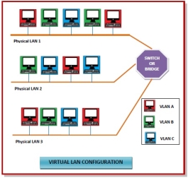
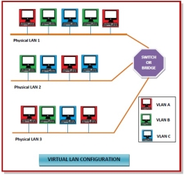
In computing terminology, the term "wired" is used to differentiate between wireless connections and those that involve cables. While wireless devices communicate over the air, a wired setup uses physical cables to transfer data between different devices and computer systems. A wired network is a common type of wired configuration. Most wired networks use Ethernet cables to transfer data between connected PCs. In a small wired network, a single router may be used to connect all the computers. Larger networks often involve multiple routers or switches that connect to each other. One of these devices typically connects to a cable modem, T1 line, or other type of Internet connection that provides Internet access to all devices connected to the network. Wired may refer to peripheral devices as well. Since many keyboards and mice are now wireless, "wired" is often used to describe input devices that connect to a USB port. Peripherals such as monitors and external hard drives also use cables, but they are rarely called wired devices since wireless options are generally not available. While many peripherals are now wireless, some users still prefer wired devices, since they have a few benefits over their wireless counterparts. For example, an Ethernet connection is not prone to signal interference that can slow down Wi-Fi connections. Additionally, wired network connections are often faster than wireless ones, which allows for faster data transfer rates. Some users also prefer wired peripherals since their is no need to replace batteries on a regular basis. Gamers especially prefer wired keyboards and mice since they have lower latency and can be backlit, thanks to the power provided by the USB connection. Virtual Local Area Networks or Virtual LANs (VLANs) are a logical group of computers that appear to be on the same LAN irrespective of the configuration of the underlying physical network. Network administrators partition the networks to match the functional requirements of the VLANs so that each VLAN comprise of a subset of ports on a single or multiple switches or bridges. This allows computers and devices in a VLAN to communicate in the simulated environment as if it is a separate LAN.
Fig 43 - VLAN
Fig 44 – Types of VLAN
|
Key takeaways
- A computer network is a group of computers linked to each other that enables the computer to communicate with another computer and share their resources, data, and applications.
- A computer network can be categorized by their size. A computer network is mainly of four types:
|
- LAN(Local Area Network)
- PAN(Personal Area Network)
- MAN(Metropolitan Area Network)
- WAN(Wide Area Network)
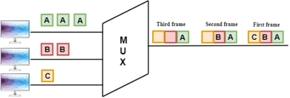
Multiplexing is a technique used to combine and send the multiple data streams over a single medium. The process of combining the data streams is known as multiplexing and hardware used for multiplexing is known as a multiplexer. Multiplexing is achieved by using a device called Multiplexer (MUX) that combines n input lines to generate a single output line. Multiplexing follows many-to-one, i.e., n input lines and one output line. Demultiplexing is achieved by using a device called Demultiplexer (DEMUX) available at the receiving end. DEMUX separates a signal into its component signals (one input and n outputs). Therefore, we can say that demultiplexing follows the one-to-many approach.
Fig 45 - Multiplexing
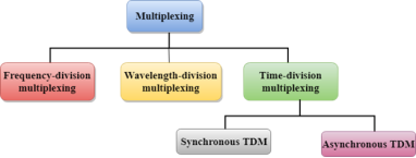
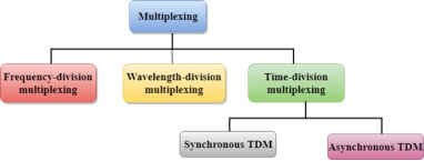
Multiplexing techniques can be classified as:
Fig 46 - Multiplexing techniques Frequency-division Multiplexing (FDM)
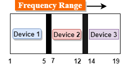
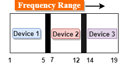
Fig 47 – Frequency range
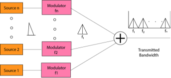
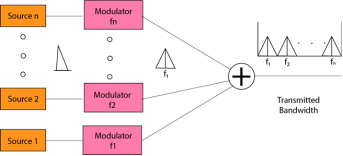
Fig 48 - FDM Advantages Of FDM:
Disadvantages Of FDM:
Applications Of FDM:
Wavelength Division Multiplexing (WDM)
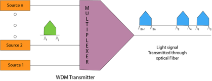
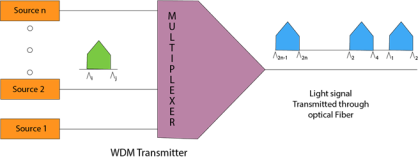
Fig 49 - WDM
Fig 50 – Fiber optic cable
There are two types of TDM:
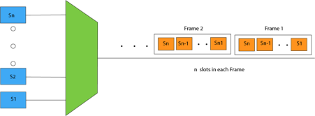
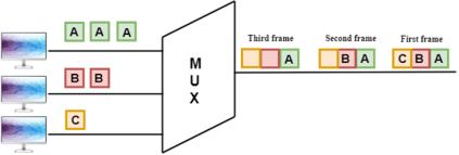
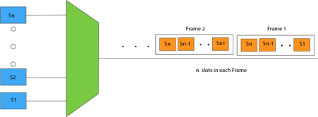
Fig 51 - Synchronous TDM Concept Of Synchronous TDM
Fig 52 - MUX In the above figure, the Synchronous TDM technique is implemented. Each device is allocated with some time slot. The time slots are transmitted irrespective of whether the sender has data to send or not. Disadvantages Of Synchronous TDM:
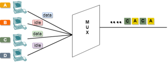
Concept Of Asynchronous TDM
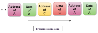
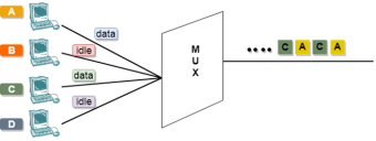
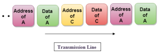
Fig 53 - Asynchronous TDM In the above diagram, there are 4 devices, but only two devices are sending the data, i.e., A and C. Therefore, the data of A and C are only transmitted through the transmission line. Frame of above diagram can be represented as:
The above figure shows that the data part contains the address to determine the source of the data. |
Key takeaways
- Multiplexing is a technique used to combine and send the multiple data streams over a single medium. The process of combining the data streams is known as multiplexing and hardware used for multiplexing is known as a multiplexer.
- Multiplexing is achieved by using a device called Multiplexer (MUX) that combines n input lines to generate a single output line. Multiplexing follows many-to-one, i.e., n input lines and one output line.
- Demultiplexing is achieved by using a device called Demultiplexer (DEMUX) available at the receiving end. DEMUX separates a signal into its component signals (one input and n outputs). Therefore, we can say that demultiplexing follows the one-to-many approach.
Spread spectrum is a technique used for wireless communications in telecommunication and radio communication. In this technique, the frequency of the transmitted signal, i.e., an electrical signal, electromagnetic signal, or acoustic signal, is deliberately varied and generates a much greater bandwidth than the signal would have if its frequency were not varied. In other words, "Spread Spectrum is a technique in which the transmitted signals of specific frequencies are varied slightly to obtain greater bandwidth as compared to initial bandwidth." Now, spread spectrum technology is widely used in radio signals transmission because it can easily reduce noise and other signal issues. Let's see an example to understand the concept of spread spectrum in wireless communication: We know that a conventional wireless signal frequency is usually specified in megahertz (MHz) or gigahertz (GHz). It does not change with time (Sometimes it is exceptionally changed in the form of small, rapid fluctuations that generally occur due to modulation). Suppose you want to listen to FM stereo at frequency 104.8 MHz on your radio, and then once you set the frequency, the signal stays at 104.8 MHz. It does not go up to 105.1 MHz or down to 101.1 MHz. You see that your set digits on the radio's frequency dial stay the same at all times. The frequency of a conventional wireless signal is kept as constant to keep bandwidth within certain limits, and the signal can be easily located by someone who wants to retrieve the information. In this conventional wireless communication model, you can face at least two problems:
The spread spectrum model is used to overcome with this conventional communication model. Here, the transmitted signal frequency is deliberately varied over a comparatively large segment of the electromagnetic radiation spectrum. This variation is done according to a specific but complicated mathematical function. If the receiver wants to intercept the signal, it must be tuned to frequencies that vary precisely according to this function. Reasons to use Spread Spectrum
There are many reasons to use this spread spectrum technique for wireless communications. The following are some reasons:
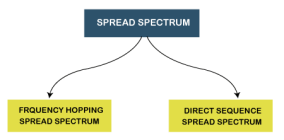
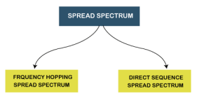
Spread Spectrum can be categorized into two types:
Fig 54 – Spread spectrum Frequency Hopping Spread Spectrum (FHSS)
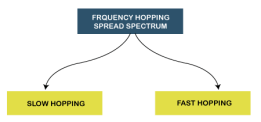
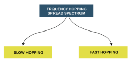
The Frequency Hopping Spread Spectrum or FHSS can also be classified into two types:
Fig 55 - Frequency Hopping Spread Spectrum
Advantages of Frequency Hopping Spread Spectrum (FHSS) The following are some advantages of frequency hopping spread spectrum (FHSS):
Disadvantages of Frequency Hopping Spread Spectrum (FHSS) The following are some disadvantages of Frequency Hopping Spread Spectrum (FHSS):
Applications of Frequency Hopping Spread Spectrum (FHSS) Following is the list of most used applications of Frequency Hopping Spread Spectrum or FHSS:
Direct Sequence Spread Spectrum (DSSS) The Direct Sequence Spread Spectrum (DSSS) is a spread-spectrum modulation technique primarily used to reduce overall signal interference in telecommunication. The Direct Sequence Spread Spectrum modulation makes the transmitted signal wider in bandwidth than the information bandwidth. In DSSS, the message bits are modulated by a bit sequencing process known as a spreading sequence. This spreading-sequence bit is known as a chip. It has a much shorter duration (larger bandwidth) than the original message bits. Following are the features of Direct Sequence Spread Spectrum or DSSS.
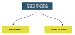
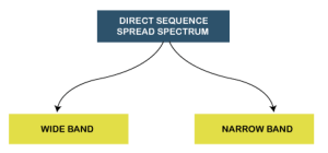
The Direct Sequence Spread Spectrum or DSSS can also be classified into two types:
Advantages of Direct Sequence Spread Spectrum (DSSS) The following are some advantages of Direct Sequence Spread Spectrum or DSSS:
Disadvantages of Direct Sequence Spread Spectrum (DSSS) The following are some disadvantages of Direct Sequence Spread Spectrum or DSSS:
Applications of Direct Sequence Spread Spectrum (DSSS) Following is the list of most used applications of Direct Sequence Spread Spectrum or DSSS:
|
Key takeaways
- Spread spectrum is a technique used for wireless communications in telecommunication and radio communication. In this technique, the frequency of the transmitted signal, i.e., an electrical signal, electromagnetic signal, or acoustic signal, is deliberately varied and generates a much greater bandwidth than the signal would have if its frequency were not varied.
- In other words, "Spread Spectrum is a technique in which the transmitted signals of specific frequencies are varied slightly to obtain greater bandwidth as compared to initial bandwidth."
- Now, spread spectrum technology is widely used in radio signals transmission because it can easily reduce noise and other signal issues.
References
1. Computer Networks, 8th Edition, Andrew S. Tanenbaum, Pearson New International Edition.
2. Internetworking with TCP/IP, Volume 1, 6th Edition Douglas Comer, Prentice Hall of India.
3. TCP/IP Illustrated, Volume 1, W. Richard Stevens, Addison-Wesley, United States of America.
