UNIT-3
Network Layer
Why is Switching Concept required? Switching concept is developed because of the following reasons:
Fig 1 – Switching mode
There are three types of switching modes:
Fig 2 – Store and forward
Fig 3 – Cut through
Fig 4 – Fragment free
Differences b/w Store-and-forward and Cut-through Switching.
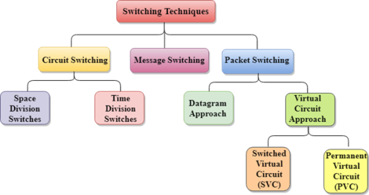
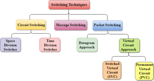
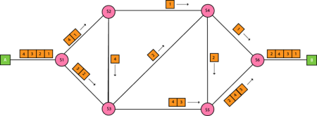
In large networks, there can be multiple paths from sender to receiver. The switching technique will decide the best route for data transmission. Switching technique is used to connect the systems for making one-to-one communication. Classification Of Switching Techniques
Fig 5 – Switching techniques
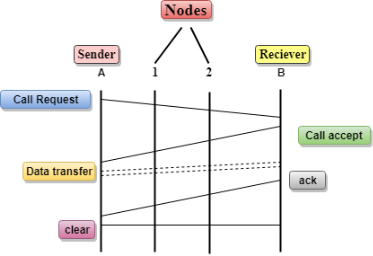
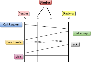
Communication through circuit switching has 3 phases:
Fig 6 - Communication Circuit Switching can use either of the two technologies:
Space Division Switches can be categorized in two ways:
The Crossbar switch is a switch that has n input lines and n output lines. The crossbar switch has n2 intersection points known as crosspoints. Disadvantage of Crossbar switch: The number of crosspoints increases as the number of stations is increased. Therefore, it becomes very expensive for a large switch. The solution to this is to use a multistage switch.
Advantages Of Circuit Switching:
Disadvantages Of Circuit Switching:
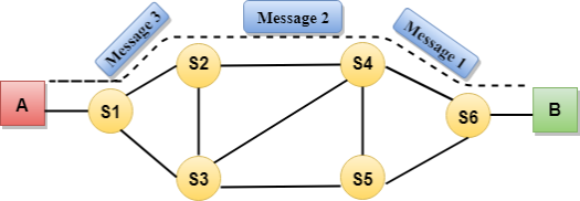
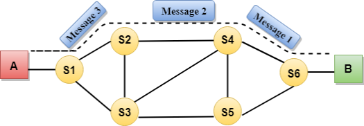
Fig 7 – Message switching Advantages Of Message Switching
Disadvantages Of Message Switching
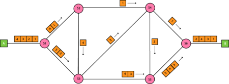
Approaches Of Packet Switching: There are two approaches to Packet Switching:
Let's understand the concept of virtual circuit switching through a diagram:
Differences b/w Datagram approach and Virtual Circuit approach
Advantages Of Packet Switching:
Disadvantages Of Packet Switching:
|
Key takeaways
- When a user accesses the internet or another computer network outside their immediate location, messages are sent through the network of transmission media. This technique of transferring the information from one computer network to another network is known as switching.
- Switching in a computer network is achieved by using switches. A switch is a small hardware device which is used to join multiple computers together with one local area network (LAN).
- Network switches operate at layer 2 (Data link layer) in the OSI model.
- Switching is transparent to the user and does not require any configuration in the home network.
- Switches are used to forward the packets based on MAC addresses.
- A Switch is used to transfer the data only to the device that has been addressed. It verifies the destination address to route the packet appropriately.
- It is operated in full duplex mode.
- Packet collision is minimum as it directly communicates between source and destination.
- It does not broadcast the message as it works with limited bandwidth.
An IP stands for internet protocol. An IP address is assigned to each device connected to a network. Each device uses an IP address for communication. It also behaves as an identifier as this address is used to identify the device on a network. It defines the technical format of the packets. Mainly, both the networks, i.e., IP and TCP, are combined together, so together, they are referred to as a TCP/IP. It creates a virtual connection between the source and the destination. We can also define an IP address as a numeric address assigned to each device on a network. An IP address is assigned to each device so that the device on a network can be identified uniquely. To facilitate the routing of packets, TCP/IP protocol uses a 32-bit logical address known as IPv4(Internet Protocol version 4). An IP address consists of two parts, i.e., the first one is a network address, and the other one is a host address. There are two types of IP addresses:
IPv4 is a version 4 of IP. It is a current version and the most commonly used IP address. It is a 32-bit address written in four numbers separated by 'dot', i.e., periods. This address is unique for each device. For example, 66.94.29.13 The above example represents the IP address in which each group of numbers separated by periods is called an Octet. Each number in an octet is in the range from 0-255. This address can produce 4,294,967,296 possible unique addresses. In today's computer network world, computers do not understand the IP addresses in the standard numeric format as the computers understand the numbers in binary form only. The binary number can be either 1 or 0. The IPv4 consists of four sets, and these sets represent the octet. The bits in each octet represent a number. Each bit in an octet can be either 1 or 0. If the bit the 1, then the number it represents will count, and if the bit is 0, then the number it represents does not count. Representation of 8 Bit Octet
The above representation shows the structure of 8- bit octet. Now, we will see how to obtain the binary representation of the above IP address, i.e., 66.94.29.13 Step 1: First, we find the binary number of 66.
To obtain 66, we put 1 under 64 and 2 as the sum of 64 and 2 is equal to 66 (64+2=66), and the remaining bits will be zero, as shown above. Therefore, the binary bit version of 66 is 01000010. Step 2: Now, we calculate the binary number of 94.
To obtain 94, we put 1 under 64, 16, 8, 4, and 2 as the sum of these numbers is equal to 94, and the remaining bits will be zero. Therefore, the binary bit version of 94 is 01011110. Step 3: The next number is 29.
To obtain 29, we put 1 under 16, 8, 4, and 1 as the sum of these numbers is equal to 29, and the remaining bits will be zero. Therefore, the binary bit version of 29 is 00011101.
Step 4: The last number is 13.
To obtain 13, we put 1 under 8, 4, and 1 as the sum of these numbers is equal to 13, and the remaining bits will be zero. Therefore, the binary bit version of 13 is 00001101. Currently, the population of the world is 7.6 billion. Every user is having more than one device connected with the internet, and private companies also rely on the internet. As we know that IPv4 produces 4 billion addresses, which are not enough for each device connected to the internet on a planet. Although the various techniques were invented, such as variable- length mask, network address translation, port address translation, classes, inter-domain translation, to conserve the bandwidth of IP address and slow down the depletion of an IP address. In these techniques, public IP is converted into a private IP due to which the user having public IP can also use the internet. But still, this was not so efficient, so it gave rise to the development of the next generation of IP addresses, i.e., IPv6. IPv4 produces 4 billion addresses, and the developers think that these addresses are enough, but they were wrong. IPv6 is the next generation of IP addresses. The main difference between IPv4 and IPv6 is the address size of IP addresses. The IPv4 is a 32-bit address, whereas IPv6 is a 128-bit hexadecimal address. IPv6 provides a large address space, and it contains a simple header as compared to IPv4. It provides transition strategies that convert IPv4 into IPv6, and these strategies are as follows:
This hexadecimal address contains both numbers and alphabets. Due to the usage of both the numbers and alphabets, IPv6 is capable of producing over 340 undecillion (3.4*1038) addresses. IPv6 is a 128-bit hexadecimal address made up of 8 sets of 16 bits each, and these 8 sets are separated by a colon. In IPv6, each hexadecimal character represents 4 bits. So, we need to convert 4 bits to a hexadecimal number at a time The address format of IPv4:
The address format of IPv6:
The above diagram shows the address format of IPv4 and IPv6. An IPv4 is a 32-bit decimal address. It contains 4 octets or fields separated by 'dot', and each field is 8-bit in size. The number that each field contains should be in the range of 0-255. Whereas an IPv6 is a 128-bit hexadecimal address. It contains 8 fields separated by a colon, and each field is 16-bit in size. Differences between IPv4 and IPv6
|
Key takeaways
- An IP stands for internet protocol. An IP address is assigned to each device connected to a network. Each device uses an IP address for communication. It also behaves as an identifier as this address is used to identify the device on a network. It defines the technical format of the packets. Mainly, both the networks, i.e., IP and TCP, are combined together, so together, they are referred to as a TCP/IP. It creates a virtual connection between the source and the destination.
- We can also define an IP address as a numeric address assigned to each device on a network. An IP address is assigned to each device so that the device on a network can be identified uniquely. To facilitate the routing of packets, TCP/IP protocol uses a 32-bit logical address known as IPv4(Internet Protocol version 4).
- An IP address consists of two parts, i.e., the first one is a network address, and the other one is a host address.
- There are two types of IP addresses:
IPv4
IPv6
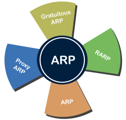
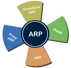
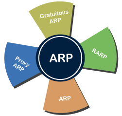
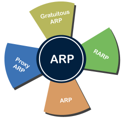
Address Resolution Protocol (ARP) and its types Address Resolution Protocol (ARP) is a communication protocol used to find the MAC (Media Access Control) address of a device from its IP address. This protocol is used when a device wants to communicate with another device on a Local Area Network or Ethernet. There are four types of Address Resolution Protocol, which is given below:
Fig 8 - ARP Proxy ARP - Proxy ARP is a method through which a Layer 3 devices may respond to ARP requests for a target that is in a different network from the sender. The Proxy ARP configured router responds to the ARP and map the MAC address of the router with the target IP address and fool the sender that it is reached at its destination. At the backend, the proxy router sends its packets to the appropriate destination because the packets contain the necessary information. Example - If Host A wants to transmit data to Host B, which is on the different network, then Host A sends an ARP request message to receive a MAC address for Host B. The router responds to Host A with its own MAC address pretend itself as a destination. When the data is transmitted to the destination by Host A, it will send to the gateway so that it sends to Host B. This is known as proxy ARP. Gratuitous ARP - Gratuitous ARP is an ARP request of the host that helps to identify the duplicate IP address. It is a broadcast request for the IP address of the router. If an ARP request is sent by a switch or router to get its IP address and no ARP responses are received, so all other nodes cannot use the IP address allocated to that switch or router. Yet if a router or switch sends an ARP request for its IP address and receives an ARP response, another node uses the IP address allocated to the switch or router. There are some primary use cases of gratuitous ARP that are given below:
Reverse ARP (RARP) - It is a networking protocol used by the client system in a local area network (LAN) to request its IPv4 address from the ARP gateway router table. A table is created by the network administrator in the gateway-router that is used to find out the MAC address to the corresponding IP address. When a new system is set up or any machine that has no memory to store the IP address, then the user has to find the IP address of the device. The device sends a RARP broadcast packet, including its own MAC address in the address field of both the sender and the receiver hardware. A host installed inside of the local network called the RARP-server is prepared to respond to such type of broadcast packet. The RARP server is then trying to locate a mapping table entry in the IP to MAC address. If any entry matches the item in the table, then the RARP server sends the response packet along with the IP address to the requesting computer. Inverse ARP (InARP) - Inverse ARP is inverse of the ARP, and it is used to find the IP addresses of the nodes from the data link layer addresses. These are mainly used for the frame relays, and ATM networks, where Layer 2 virtual circuit addressing are often acquired from Layer 2 signaling. When using these virtual circuits, the relevant Layer 3 addresses are available. ARP conversions Layer 3 addresses to Layer 2 addresses. However, its opposite address can be defined by InARP. The InARP has a similar packet format as ARP, but operational codes are different.
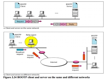
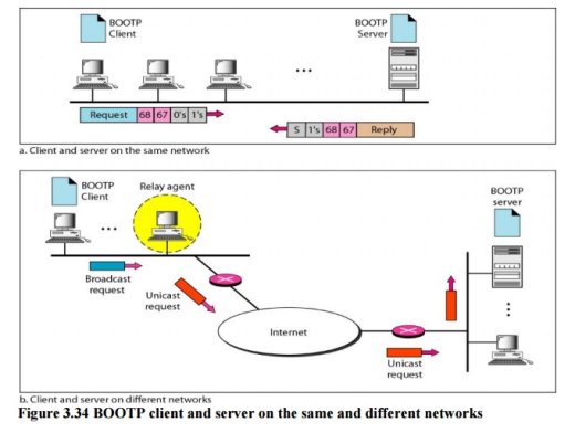
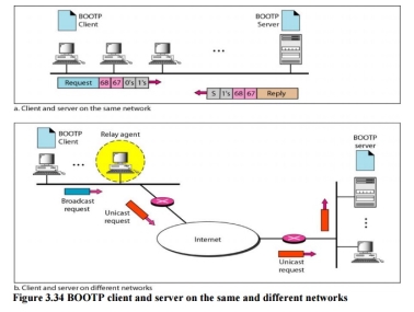
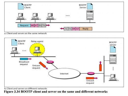
Fig 9 – BOOTP client and server on the same and different networks The Bootstrap Protocol (BOOTP) is a client/server protocol designed to provide physical address to logical address mapping. BOOTP The Bootstrap Protocol (BOOTP) is a client/server protocol designed to provide physical address to logical address mapping. BOOTP is an application layer protocol. The administrator may put the client and the server on the same network or on different networks
Fig 10 – BOOTP client and server on the same and different networks One of the advantages of BOOTP over RARP is that the client and server are application-layer processes. As in other application-layer processes, a client can be in one network and the server in another, separated by several other networks. However, there is one problem that must be solved. The BOOTP request is broadcast because the client does not know the IP address of the server. A broadcast IP datagram cannot pass through any router. To solve the problem, there is a need for an intermediary. One of the hosts (or a router that can be configured to operate at the application layer) can be used as a relay. The host in this case is called a relay agent. The relay agent knows the unicast address of a BOOTP server. When it receives this type of packet, it encapsulates the message in a unicast datagram and sends the request to the BOOTP server. The packet, carrying a unicast destination address, is routed by any router and reaches the BOOTP server. The BOOTP server knows the message comes from a relay agent because one of the fields in the request message defines the IP address of the relay agent. The relay agent, after receiving the reply, sends it to the BOOTP client. Dynamic Host Configuration Protocol Dynamic Host Configuration Protocol (DHCP) is a network management protocol used to dynamically assign an IP address to nay device, or node, on a network so they can communicate using IP (Internet Protocol). DHCP automates and centrally manages these configurations. There is no need to manually assign IP addresses to new devices. Therefore, there is no requirement for any user configuration to connect to a DHCP based network. DHCP can be implemented on local networks as well as large enterprise networks. DHCP is the default protocol used by the most routers and networking equipment. DHCP is also called RFC (Request for comments) 2131.
DHCP is also used to configure the proper subnet mask, default gateway and DNS server information on the node or device. There are many versions of DCHP are available for use in IPV4 (Internet Protocol Version 4) and IPV6 (Internet Protocol Version 6). DHCP runs at the application layer of the TCP/IP protocol stack to dynamically assign IP addresses to DHCP clients/nodes and to allocate TCP/IP configuration information to the DHCP clients. Information includes subnet mask information, default gateway, IP addresses and domain name system addresses. DHCP is based on client-server protocol in which servers manage a pool of unique IP addresses, as well as information about client configuration parameters, and assign addresses out of those address pools. The DHCP lease process works as follows:
When working with DHCP, it is important to understand all of the components. Following are the list of components:
There are following benefits of DHCP: Centralized administration of IP configuration: DHCP IP configuration information can be stored in a single location and enables that administrator to centrally manage all IP address configuration information. Dynamic host configuration: DHCP automates the host configuration process and eliminates the need to manually configure individual host. When TCP/IP (Transmission control protocol/Internet protocol) is first deployed or when IP infrastructure changes are required. Seamless IP host configuration: The use of DHCP ensures that DHCP clients get accurate and timely IP configuration IP configuration parameter such as IP address, subnet mask, default gateway, IP address of DND server and so on without user intervention. Flexibility and scalability: Using DHCP gives the administrator increased flexibility, allowing the administrator to move easily change IP configuration when the infrastructure changes. |
Key takeaways
- Address Resolution Protocol (ARP) is a communication protocol used to find the MAC (Media Access Control) address of a device from its IP address. This protocol is used when a device wants to communicate with another device on a Local Area Network or Ethernet.
- There are four types of Address Resolution Protocol, which is given below:
- Proxy ARP
- Gratuitous ARP
- Reverse ARP (RARP)
- Inverse ARP
|
When a device has multiple paths to reach a destination, it always selects one path by preferring it over others. This selection process is termed as Routing. Routing is done by special network devices called routers or it can be done by means of software processes.The software based routers have limited functionality and limited scope. A router is always configured with some default route. A default route tells the router where to forward a packet if there is no route found for specific destination. In case there are multiple path existing to reach the same destination, router can make decision based on the following information:
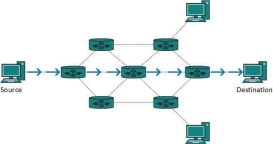
Routes can be statically configured or dynamically learnt. One route can be configured to be preferred over others. Most of the traffic on the internet and intranets known as unicast data or unicast traffic is sent with specified destination. Routing unicast data over the internet is called unicast routing. It is the simplest form of routing because the destination is already known. Hence the router just has to look up the routing table and forward the packet to next hop.
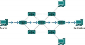
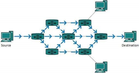
Fig 10 – Unicast routing By default, the broadcast packets are not routed and forwarded by the routers on any network. Routers create broadcast domains. But it can be configured to forward broadcasts in some special cases. A broadcast message is destined to all network devices. Broadcast routing can be done in two ways (algorithm):
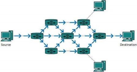
This method consumes lots of bandwidth and router must destination address of each node.
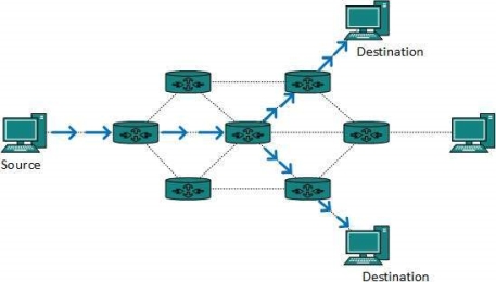
Fig 11 – Broadcast routing This method is easy on router's CPU but may cause the problem of duplicate packets received from peer routers. Reverse path forwarding is a technique, in which router knows in advance about its predecessor from where it should receive broadcast. This technique is used to detect and discard duplicates. Multicast routing is special case of broadcast routing with significance difference and challenges. In broadcast routing, packets are sent to all nodes even if they do not want it. But in Multicast routing, the data is sent to only nodes which wants to receive the packets.
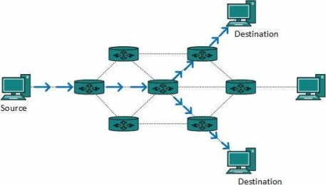
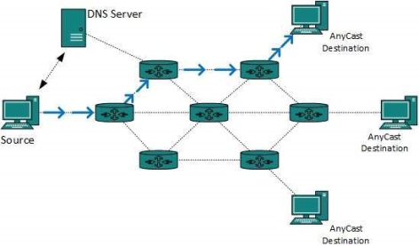
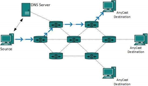
Fig 12 – Multicast routing The router must know that there are nodes, which wish to receive multicast packets (or stream) then only it should forward. Multicast routing works spanning tree protocol to avoid looping. Multicast routing also uses reverse path Forwarding technique, to detect and discard duplicates and loops. Anycast packet forwarding is a mechanism where multiple hosts can have same logical address. When a packet destined to this logical address is received, it is sent to the host which is nearest in routing topology.
Fig 13 – Anycast routing Anycast routing is done with help of DNS server. Whenever an Anycast packet is received it is enquired with DNS to where to send it. DNS provides the IP address which is the nearest IP configured on it. There are two kinds of routing protocols available to route unicast packets: Distance Vector is simple routing protocol which takes routing decision on the number of hops between source and destination. A route with less number of hops is considered as the best route. Every router advertises its set best routes to other routers. Ultimately, all routers build up their network topology based on the advertisements of their peer routers, For example Routing Information Protocol (RIP). Link State protocol is slightly complicated protocol than Distance Vector. It takes into account the states of links of all the routers in a network. This technique helps routes build a common graph of the entire network. All routers then calculate their best path for routing purposes.for example, Open Shortest Path First (OSPF) and Intermediate System to Intermediate System (ISIS). Unicast routing protocols use graphs while Multicast routing protocols use trees, i.e. spanning tree to avoid loops. The optimal tree is called shortest path spanning tree.
Protocol Independent Multicast is commonly used now. It has two flavors:
This mode uses source-based trees. It is used in dense environment such as LAN.
This mode uses shared trees. It is used in sparse environment such as WAN. The routing algorithms are as follows: Flooding is simplest method packet forwarding. When a packet is received, the routers send it to all the interfaces except the one on which it was received. This creates too much burden on the network and lots of duplicate packets wandering in the network. Time to Live (TTL) can be used to avoid infinite looping of packets. There exists another approach for flooding, which is called Selective Flooding to reduce the overhead on the network. In this method, the router does not flood out on all the interfaces, but selective ones. Routing decision in networks, are mostly taken on the basis of cost between source and destination. Hop count plays major role here. Shortest path is a technique which uses various algorithms to decide a path with minimum number of hops. Common shortest path algorithms are:
Routing metrics and costs are used for determining the best route to the destination. The factors used by the protocols to determine the shortest path, these factors are known as a metric. Metrics are the network variables used to determine the best route to the destination. For some protocols use the static metrics means that their value cannot be changed and for some other routing protocols use the dynamic metrics means that their value can be assigned by the system administrator. The most common metric values are given below:
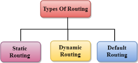
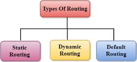
Routing can be classified into three categories:
Fig 14 – Types of routing
Following are the advantages of Static Routing:
Disadvantages of Static Routing: Following are the disadvantages of Static Routing:
The Dynamic protocol should have the following features:
Advantages of Dynamic Routing:
Disadvantages of Dynamic Routing:
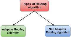
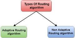
Classification of a Routing algorithm The Routing algorithm is divided into two categories:
Fig 15 – Types of routing algorithm
An adaptive routing algorithm can be classified into three parts:
Non-Adaptive Routing algorithm
The Non-Adaptive Routing algorithm is of two types: Flooding: In case of flooding, every incoming packet is sent to all the outgoing links except the one from it has been reached. The disadvantage of flooding is that node may contain several copies of a particular packet. Random walks: In case of random walks, a packet sent by the node to one of its neighbors randomly. An advantage of using random walks is that it uses the alternative routes very efficiently. Differences b/w Adaptive and Non-Adaptive Routing Algorithm
|
Key takeaways
- When a device has multiple paths to reach a destination, it always selects one path by preferring it over others. This selection process is termed as Routing. Routing is done by special network devices called routers or it can be done by means of software processes.The software based routers have limited functionality and limited scope.
- A router is always configured with some default route. A default route tells the router where to forward a packet if there is no route found for specific destination. In case there are multiple path existing to reach the same destination, router can make decision based on the following information:
- Hop Count
- Bandwidth
- Metric
- Prefix-length
- Delay
3. Routes can be statically configured or dynamically learnt. One route can be configured to be preferred over others.
References
1. Computer Networks, 8th Edition, Andrew S. Tanenbaum, Pearson New International Edition.
2. Internetworking with TCP/IP, Volume 1, 6th Edition Douglas Comer, Prentice Hall of India.
3. TCP/IP Illustrated, Volume 1, W. Richard Stevens, Addison-Wesley, United States of America.


