Unit – 4
Transformers
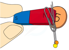
- Iron
- Steel (an alloy of iron)
- Nickel
- Cobalt
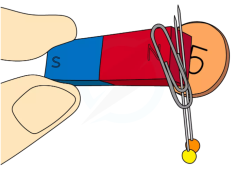
- Are easy to magnetise
- Easily lose their magnetism
- Are hard to magnetise
- Do not easily lose their magnetism
Bh Characteristics
B-H Curve
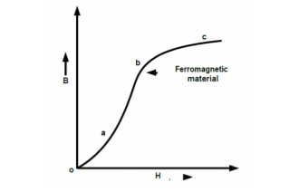
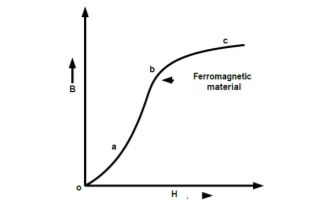
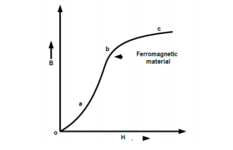
The curve plotted between flux density B and magnetizing force H of a material is called magnetizing or B-H curve.
The shape of curve is non-linear. This indicates that relative permeability (µr = B / µ0H) of a material is not constant, but it varies.
B-H curves are extremely useful to analyse the magnetic circuit. If value of flux density and dimension of magnetic circuit is known than from B-H curve total ampere turn can be easily known.
Ideal And Practical Transformer
Ideal Transformer
An ideal transformer is one that has
Although an ideal transformer cannot be physically realized, yet its study provides a very powerful tool in the analysis of a practical transformer. In fact, practical transformers have properties that approach remarkably close to an ideal transformer.
Ideal Transformer and Phasor Diagram
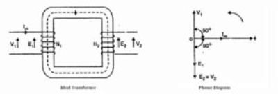
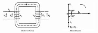
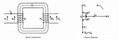
Consider an ideal transformer on no load i.e., the secondary is open circuited as shown in the figure. Under such conditions, the primary is simply a coil of pure inductance.
When an alternating voltage V₁ is applied to the primary, it draws a small magnetizing current Iₘ which lags the applied voltage by 90°. This alternating current Iₘ produces an alternating flux ϕ which is proportional to and in phase with it.
The alternating flux ϕ links both the windings and induces e.m.f. E₁ in the primary and e.m.f. E₂ in the secondary. The primary e.m.f. E₁ is, at every instant, equal to and in opposition to V₁ (Lenz’s law). Both e.m.f.s E₁, and E₂ lag flux ϕ by 90°. However, their magnitudes depend upon the number of primary and secondary turns.
Phasor Diagram of Ideal Transformer
The phasor diagram of an ideal transformer on no load is also shown above. Since flux ϕ is common to both the windings, it has been taken as the reference phasor.
The primary e.m.f. E₁ and secondary e.m.f. E₂ lag behind the flux ϕ by 90°.
Note that E₁ and E₂ are in phase. But E₁ is equal to V₁ and 180° out of phase with it.
Practical Transformer
A practical transformer differs from the ideal transformer in many respects. The practical transformer has,
1. Iron Losses
Since the iron core is subjected to alternating flux, there occurs eddy current and hysteresis loss in it. These two losses together are known as iron losses or core losses. The iron losses depend upon the supply frequency, the maximum flux density in the core, volume of the core, etc.
2. Winding resistances
Since the windings consist of copper conductors, it immediately follows that both primary and secondary will have winding resistance. The primary resistance R₁ and secondary resistance R₂ act in series with the respective windings as shown in the figure.
When current flows through the windings, there will be power loss as well as a loss in voltage due to IR drop. This will affect the power factor and E₁ will be less than V₁ while V₂ will be less than E₂.
TYPES OF MAGNETIC MATERIAL
1.Paramagnetic Materials.
The materials, which are not strongly attracted by a magnet, such as aluminium, tin, platinum, magnesium, manganese etc., are known as paramagnetic materials. Their relative permeability is small but positive.
Such materials are slightly magnetized when placed in a strong magnetic field and act in the direction of the magnetic field. In paramagnetic materials the individual atomic dipoles are oriented in a random fashion, as shown in Figure.

The resultant magnetic field is, therefore, negligible. When an external magnetic field is applied, the permanent magnetic dipoles orient themselves parallel to the applied magnetic field and give rise to a positive magnetization. Since the orientation of the dipoles parallel to the applied magnetic field is not complete, the magnetization is small. These materials have little application in the field of electrical engineering.
2. Diamagnetic Materials. The materials which are repelled by a magnet such as zinc, mercury, lead, sulphur, copper, silver, bismuth, wood etc., are known as diamagnetic materials.
Their permeability is slightly less than unity.
For example, the relative permeabilities of bismuth, copper and wood are 0.99983, 0.999995 and 0.9999995 respectively.
They are slightly magnetized when placed in a strong magnetic field and act in the direction opposite to that of applied magnetic field. In diamagnetic materials, the two relatively weak magnetic fields (one caused due to orbital revolution and other due to axial rotation) are in opposite directions and cancel each other. Permanent magnetic dipoles are absent in them.
3. Ferromagnetic Materials. Ferromagnetism may be thought of as a special case of para magnetism in which the individual spin magnetic moments are interacting or coupled. As with paramagnets, ferromagnets have strong and positive magnetic susceptibility. Ferromagnetism is possible only when atoms are arranged in a lattice and the atomic magnetic moments interact to align parallel with each other. This field is sufficient to magnetize the material to saturation. Unlike paramagnets, when the applied field is removed, they retain a component of magnetization in the direction of the applied field – they are “permanently” magnetized Ferromagnetic materials are of two types: (a) soft magnetic material and (b) hard magnetic materials.
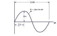
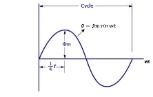
As primary winding excited by the a sinusoidal alternating voltage an alternating current flows in the winding producing an alternating varying flux Ø
Ø = Øm sin wt
As per Faradays Law of Electromagnetic Induction emf E1 is induced
E1 = N1 
E1 = N1  (Ø Sin wt)
= - N1 Øm w Cos wt
Sin (90-wt)
= - Sin (wt-90)
 E1 = N1 Øm w Sin (wt-90)
 w =
w = 
 E1 =
E1 =  N1 Ø m Sin (wt-90)
Max value of E1 = E max
Is when Sin (wt-90) =  1
1
E1 max =  N1 Ø m
Hence rms value of induced EMF in primary winding
E1 rms =  =
= 
 E1 = 4.44 F Ø m N1
 Similarly RMS value of induced EMF in secondary wdg Is
E2 = 4.44 F Ø m N2
There are 2 types of losses occurring in a transformer
A) 1. Core loss or Iron loss
B) 2. Copper loss


1 Hysteresis loss
2 Reedy current loss
Hysteresis loss: The iron loss occurring in the core of T/F due to the Hysteresis curve of the magnetic material used for core is called as Hysteresis loss.
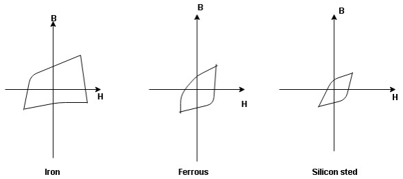
Hysteresis curve is the curve as loop which shows the properly of magnetic material to lag the flux density B behind the field Intensely H
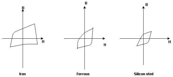
Above is the 3 different loops (Hysteresis of 3 diff. Materials)
 the selection of magnetic material for the construction of core depends upon Hysteresis loop of that material having tall and narrow Hysteresis loop is selected for the T/F core
 silicon Steel
Hysteresis loss depends on fold factor
PH = KH. Bm1.67 F  V – watts
Where KH = constant (Hyst)
Bm = max Flux density
F = Frequency
 = Volume of core.
A] Reedy current loss :
This loss is due to the flow of reedy (circular) current in the core caused by induced emf in core
PE = Ke Bm2 f2 t2 v – watts
Where
Ke = reedy current const.
t = thickness of core
It can be reduced by using stacks of laminations instead of solid core
B] Copper loss : PCU
The Copper loss is due to resistance of the primary and secondary winding.
It is load dependent / current dependent loss
As load on a transformer is variable (changing)  current changes
  copper loss is a variable loss
Total C is loss = I12 R12 + I22 R22
Copper loss depends upon load on T/F and is proportional to square of load current or KVA rating of transformer
 PCU
PCU  2
2  (KVA)2
F.L = full load
 PCU (at half load) =
  2 PCu F.L
= (0.5)2 PCU F.L.
Or PCu ( load) = (
 )2 PCu F.L
Find no load vtg E2
Remove the load and measure the reading of V2 meter Ew will get no load vtg E2
 E2 = V2 when load is absent
Now connect load and measure V2 this is now the load voltage

For each reading E2 will be same but V2 will change acc. To load
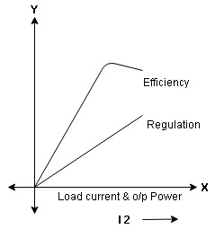
Efficiency:
Efficiency it is the ratio output power to input power of transformer
 =
= 
Output power = input power – total loss
 Input power = O/P + losses

O/P power = KVA  Cos Ø2
  1000
1000
Or = V2  I2 Cos Ø2
Losses = Pi + PCU (F.L)
= iron + copper loss
 Full load =
 Half load(H.L) or 50% or 0.5 =

 =
= 
Maximum efficiency – for numerical :
The efficiency of T/F is maximum when copper loss equates iron loss this is the condition for max efficiency
ie Pi = PCU
 =
= 
 PCU = Pi at max n
where KVA at max n given = Full load KVA 

Auto Transformer
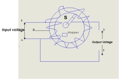
An auto Transformer is a special types of transformer such that a part of the
winding is common to both primary as well as secondary
It has only One winding wended on a laminated magnetic core
With the help of auto Transformer the voltage can be stepped up and stepped
down at any desired value
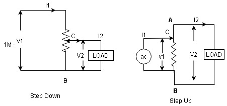
Fig A shows auto T/F as step down T/F variable terminal B C is connected to load and it acts as secondary wdg.
The position of point C is called as topping point can be selected as per requirement
Fig. B show auto T/F as step up T/F variable terminal B C is connected to supply side ie ac side and it acts as secondary winding
The operating principle of auto Transformer is same as that of 2 winding Transformer
Advantages
Disadvantage:
As low voltage and high voltage sides are not separate then there is always risk of electric shocks when use for high vtg. Applications
Applications
Three-Phase Transformer Connections:
Connection | Phase Voltage | Line Voltage | Phase current | Line current |
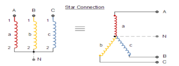
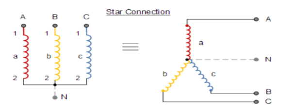
Star | Vp = VL /3 | VL = √ 3 x VP | Ip = IL | Ip = IL |
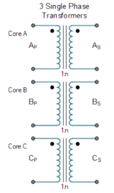
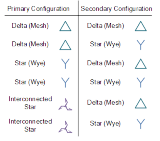
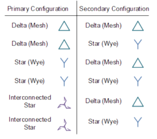
There are four different ways in which three single-phase transformers may be connected together between their primary and secondary three-phase circuits. These four standard configurations are given as: Delta-Delta (Dd), Star-Star (Yy), Star-Delta (Yd), and Delta-Star (Dy).
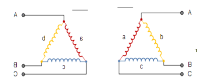

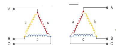
The delta-delta connection nevertheless has one big advantage over the star-delta configuration, in that if one transformer of a group of three should become faulty or disabled, the two remaining ones will continue to deliver three-phase power with a capacity equal to approximately two thirds of the original output from the transformer unit.
References:
Unit – 4
Transformers
- Iron
- Steel (an alloy of iron)
- Nickel
- Cobalt
- Are easy to magnetise
- Easily lose their magnetism
- Are hard to magnetise
- Do not easily lose their magnetism
Bh Characteristics
B-H Curve
The curve plotted between flux density B and magnetizing force H of a material is called magnetizing or B-H curve.
The shape of curve is non-linear. This indicates that relative permeability (µr = B / µ0H) of a material is not constant, but it varies.
B-H curves are extremely useful to analyse the magnetic circuit. If value of flux density and dimension of magnetic circuit is known than from B-H curve total ampere turn can be easily known.
Ideal And Practical Transformer
Ideal Transformer
An ideal transformer is one that has
Although an ideal transformer cannot be physically realized, yet its study provides a very powerful tool in the analysis of a practical transformer. In fact, practical transformers have properties that approach remarkably close to an ideal transformer.
Ideal Transformer and Phasor Diagram
Consider an ideal transformer on no load i.e., the secondary is open circuited as shown in the figure. Under such conditions, the primary is simply a coil of pure inductance.
When an alternating voltage V₁ is applied to the primary, it draws a small magnetizing current Iₘ which lags the applied voltage by 90°. This alternating current Iₘ produces an alternating flux ϕ which is proportional to and in phase with it.
The alternating flux ϕ links both the windings and induces e.m.f. E₁ in the primary and e.m.f. E₂ in the secondary. The primary e.m.f. E₁ is, at every instant, equal to and in opposition to V₁ (Lenz’s law). Both e.m.f.s E₁, and E₂ lag flux ϕ by 90°. However, their magnitudes depend upon the number of primary and secondary turns.
Phasor Diagram of Ideal Transformer
The phasor diagram of an ideal transformer on no load is also shown above. Since flux ϕ is common to both the windings, it has been taken as the reference phasor.
The primary e.m.f. E₁ and secondary e.m.f. E₂ lag behind the flux ϕ by 90°.
Note that E₁ and E₂ are in phase. But E₁ is equal to V₁ and 180° out of phase with it.
Practical Transformer
A practical transformer differs from the ideal transformer in many respects. The practical transformer has,
1. Iron Losses
Since the iron core is subjected to alternating flux, there occurs eddy current and hysteresis loss in it. These two losses together are known as iron losses or core losses. The iron losses depend upon the supply frequency, the maximum flux density in the core, volume of the core, etc.
2. Winding resistances
Since the windings consist of copper conductors, it immediately follows that both primary and secondary will have winding resistance. The primary resistance R₁ and secondary resistance R₂ act in series with the respective windings as shown in the figure.
When current flows through the windings, there will be power loss as well as a loss in voltage due to IR drop. This will affect the power factor and E₁ will be less than V₁ while V₂ will be less than E₂.
TYPES OF MAGNETIC MATERIAL
1.Paramagnetic Materials.
The materials, which are not strongly attracted by a magnet, such as aluminium, tin, platinum, magnesium, manganese etc., are known as paramagnetic materials. Their relative permeability is small but positive.
Such materials are slightly magnetized when placed in a strong magnetic field and act in the direction of the magnetic field. In paramagnetic materials the individual atomic dipoles are oriented in a random fashion, as shown in Figure.

The resultant magnetic field is, therefore, negligible. When an external magnetic field is applied, the permanent magnetic dipoles orient themselves parallel to the applied magnetic field and give rise to a positive magnetization. Since the orientation of the dipoles parallel to the applied magnetic field is not complete, the magnetization is small. These materials have little application in the field of electrical engineering.
2. Diamagnetic Materials. The materials which are repelled by a magnet such as zinc, mercury, lead, sulphur, copper, silver, bismuth, wood etc., are known as diamagnetic materials.
Their permeability is slightly less than unity.
For example, the relative permeabilities of bismuth, copper and wood are 0.99983, 0.999995 and 0.9999995 respectively.
They are slightly magnetized when placed in a strong magnetic field and act in the direction opposite to that of applied magnetic field. In diamagnetic materials, the two relatively weak magnetic fields (one caused due to orbital revolution and other due to axial rotation) are in opposite directions and cancel each other. Permanent magnetic dipoles are absent in them.
3. Ferromagnetic Materials. Ferromagnetism may be thought of as a special case of para magnetism in which the individual spin magnetic moments are interacting or coupled. As with paramagnets, ferromagnets have strong and positive magnetic susceptibility. Ferromagnetism is possible only when atoms are arranged in a lattice and the atomic magnetic moments interact to align parallel with each other. This field is sufficient to magnetize the material to saturation. Unlike paramagnets, when the applied field is removed, they retain a component of magnetization in the direction of the applied field – they are “permanently” magnetized Ferromagnetic materials are of two types: (a) soft magnetic material and (b) hard magnetic materials.
Unit – 4
Transformers
Unit – 4
Transformers
- Iron
- Steel (an alloy of iron)
- Nickel
- Cobalt
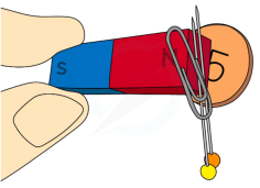
- Are easy to magnetise
- Easily lose their magnetism
- Are hard to magnetise
- Do not easily lose their magnetism
Bh Characteristics
B-H Curve
The curve plotted between flux density B and magnetizing force H of a material is called magnetizing or B-H curve.
The shape of curve is non-linear. This indicates that relative permeability (µr = B / µ0H) of a material is not constant, but it varies.
B-H curves are extremely useful to analyse the magnetic circuit. If value of flux density and dimension of magnetic circuit is known than from B-H curve total ampere turn can be easily known.
Ideal And Practical Transformer
Ideal Transformer
An ideal transformer is one that has
Although an ideal transformer cannot be physically realized, yet its study provides a very powerful tool in the analysis of a practical transformer. In fact, practical transformers have properties that approach remarkably close to an ideal transformer.
Ideal Transformer and Phasor Diagram
Consider an ideal transformer on no load i.e., the secondary is open circuited as shown in the figure. Under such conditions, the primary is simply a coil of pure inductance.
When an alternating voltage V₁ is applied to the primary, it draws a small magnetizing current Iₘ which lags the applied voltage by 90°. This alternating current Iₘ produces an alternating flux ϕ which is proportional to and in phase with it.
The alternating flux ϕ links both the windings and induces e.m.f. E₁ in the primary and e.m.f. E₂ in the secondary. The primary e.m.f. E₁ is, at every instant, equal to and in opposition to V₁ (Lenz’s law). Both e.m.f.s E₁, and E₂ lag flux ϕ by 90°. However, their magnitudes depend upon the number of primary and secondary turns.
Phasor Diagram of Ideal Transformer
The phasor diagram of an ideal transformer on no load is also shown above. Since flux ϕ is common to both the windings, it has been taken as the reference phasor.
The primary e.m.f. E₁ and secondary e.m.f. E₂ lag behind the flux ϕ by 90°.
Note that E₁ and E₂ are in phase. But E₁ is equal to V₁ and 180° out of phase with it.
Practical Transformer
A practical transformer differs from the ideal transformer in many respects. The practical transformer has,
1. Iron Losses
Since the iron core is subjected to alternating flux, there occurs eddy current and hysteresis loss in it. These two losses together are known as iron losses or core losses. The iron losses depend upon the supply frequency, the maximum flux density in the core, volume of the core, etc.
2. Winding resistances
Since the windings consist of copper conductors, it immediately follows that both primary and secondary will have winding resistance. The primary resistance R₁ and secondary resistance R₂ act in series with the respective windings as shown in the figure.
When current flows through the windings, there will be power loss as well as a loss in voltage due to IR drop. This will affect the power factor and E₁ will be less than V₁ while V₂ will be less than E₂.
TYPES OF MAGNETIC MATERIAL
1.Paramagnetic Materials.
The materials, which are not strongly attracted by a magnet, such as aluminium, tin, platinum, magnesium, manganese etc., are known as paramagnetic materials. Their relative permeability is small but positive.
Such materials are slightly magnetized when placed in a strong magnetic field and act in the direction of the magnetic field. In paramagnetic materials the individual atomic dipoles are oriented in a random fashion, as shown in Figure.

The resultant magnetic field is, therefore, negligible. When an external magnetic field is applied, the permanent magnetic dipoles orient themselves parallel to the applied magnetic field and give rise to a positive magnetization. Since the orientation of the dipoles parallel to the applied magnetic field is not complete, the magnetization is small. These materials have little application in the field of electrical engineering.
2. Diamagnetic Materials. The materials which are repelled by a magnet such as zinc, mercury, lead, sulphur, copper, silver, bismuth, wood etc., are known as diamagnetic materials.
Their permeability is slightly less than unity.
For example, the relative permeabilities of bismuth, copper and wood are 0.99983, 0.999995 and 0.9999995 respectively.
They are slightly magnetized when placed in a strong magnetic field and act in the direction opposite to that of applied magnetic field. In diamagnetic materials, the two relatively weak magnetic fields (one caused due to orbital revolution and other due to axial rotation) are in opposite directions and cancel each other. Permanent magnetic dipoles are absent in them.
3. Ferromagnetic Materials. Ferromagnetism may be thought of as a special case of para magnetism in which the individual spin magnetic moments are interacting or coupled. As with paramagnets, ferromagnets have strong and positive magnetic susceptibility. Ferromagnetism is possible only when atoms are arranged in a lattice and the atomic magnetic moments interact to align parallel with each other. This field is sufficient to magnetize the material to saturation. Unlike paramagnets, when the applied field is removed, they retain a component of magnetization in the direction of the applied field – they are “permanently” magnetized Ferromagnetic materials are of two types: (a) soft magnetic material and (b) hard magnetic materials.
As primary winding excited by the a sinusoidal alternating voltage an alternating current flows in the winding producing an alternating varying flux Ø
Ø = Øm sin wt
As per Faradays Law of Electromagnetic Induction emf E1 is induced
E1 = N1 
E1 = N1  (Ø Sin wt)
= - N1 Øm w Cos wt
Sin (90-wt)
= - Sin (wt-90)
 E1 = N1 Øm w Sin (wt-90)
 w =
w = 
 E1 =
E1 =  N1 Ø m Sin (wt-90)
Max value of E1 = E max
Is when Sin (wt-90) =  1
1
E1 max =  N1 Ø m
Hence rms value of induced EMF in primary winding
E1 rms =  =
= 
 E1 = 4.44 F Ø m N1
 Similarly RMS value of induced EMF in secondary wdg Is
E2 = 4.44 F Ø m N2
There are 2 types of losses occurring in a transformer
A) 1. Core loss or Iron loss
B) 2. Copper loss


1 Hysteresis loss
2 Reedy current loss
Hysteresis loss: The iron loss occurring in the core of T/F due to the Hysteresis curve of the magnetic material used for core is called as Hysteresis loss.
Hysteresis curve is the curve as loop which shows the properly of magnetic material to lag the flux density B behind the field Intensely H
Above is the 3 different loops (Hysteresis of 3 diff. Materials)
 the selection of magnetic material for the construction of core depends upon Hysteresis loop of that material having tall and narrow Hysteresis loop is selected for the T/F core
 silicon Steel
Hysteresis loss depends on fold factor
PH = KH. Bm1.67 F  V – watts
Where KH = constant (Hyst)
Bm = max Flux density
F = Frequency
 = Volume of core.
A] Reedy current loss :
This loss is due to the flow of reedy (circular) current in the core caused by induced emf in core
PE = Ke Bm2 f2 t2 v – watts
Where
Ke = reedy current const.
t = thickness of core
It can be reduced by using stacks of laminations instead of solid core
B] Copper loss : PCU
The Copper loss is due to resistance of the primary and secondary winding.
It is load dependent / current dependent loss
As load on a transformer is variable (changing)  current changes
  copper loss is a variable loss
Total C is loss = I12 R12 + I22 R22
Copper loss depends upon load on T/F and is proportional to square of load current or KVA rating of transformer
 PCU
PCU  2
2  (KVA)2
F.L = full load
 PCU (at half load) =
  2 PCu F.L
= (0.5)2 PCU F.L.
Or PCu ( load) = (
 )2 PCu F.L
Find no load vtg E2
Remove the load and measure the reading of V2 meter Ew will get no load vtg E2
 E2 = V2 when load is absent
Now connect load and measure V2 this is now the load voltage

For each reading E2 will be same but V2 will change acc. To load
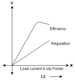
Efficiency:
Efficiency it is the ratio output power to input power of transformer
 =
= 
Output power = input power – total loss
 Input power = O/P + losses

O/P power = KVA  Cos Ø2
  1000
1000
Or = V2  I2 Cos Ø2
Losses = Pi + PCU (F.L)
= iron + copper loss
 Full load =
 Half load(H.L) or 50% or 0.5 =

 =
= 
Maximum efficiency – for numerical :
The efficiency of T/F is maximum when copper loss equates iron loss this is the condition for max efficiency
ie Pi = PCU
 =
= 
 PCU = Pi at max n
where KVA at max n given = Full load KVA 

Auto Transformer
An auto Transformer is a special types of transformer such that a part of the
winding is common to both primary as well as secondary
It has only One winding wended on a laminated magnetic core
With the help of auto Transformer the voltage can be stepped up and stepped
down at any desired value
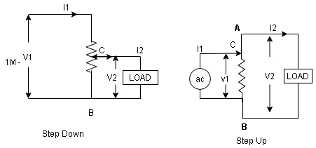
Fig A shows auto T/F as step down T/F variable terminal B C is connected to load and it acts as secondary wdg.
The position of point C is called as topping point can be selected as per requirement
Fig. B show auto T/F as step up T/F variable terminal B C is connected to supply side ie ac side and it acts as secondary winding
The operating principle of auto Transformer is same as that of 2 winding Transformer
Advantages
Disadvantage:
As low voltage and high voltage sides are not separate then there is always risk of electric shocks when use for high vtg. Applications
Applications
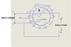
Three-Phase Transformer Connections:
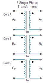
Connection | Phase Voltage | Line Voltage | Phase current | Line current |
Star | Vp = VL /3 | VL = √ 3 x VP | Ip = IL | Ip = IL |
There are four different ways in which three single-phase transformers may be connected together between their primary and secondary three-phase circuits. These four standard configurations are given as: Delta-Delta (Dd), Star-Star (Yy), Star-Delta (Yd), and Delta-Star (Dy).

The delta-delta connection nevertheless has one big advantage over the star-delta configuration, in that if one transformer of a group of three should become faulty or disabled, the two remaining ones will continue to deliver three-phase power with a capacity equal to approximately two thirds of the original output from the transformer unit.
References: