Unit – 4
DC MACHINES
They convert mechanical energy into electrical energy. The energy conversion is based on the principle of production of induced emf. The construction and working are explained below.
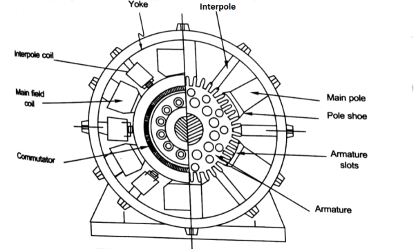
Construction – A simple generator is shown below, the essential parts of which are
1) Yoke – It is the outer frame of machine which carries the magnetic flux produced by poles and also provides mechanical support to the poles. The yoke is generally made of cast steel or rolled steel.
2) Pole shoes – They are made up of thin lamination of anmealed steel, which are piled up under hydraulic pressure. They spread out the flux in the air gap. They reduce the reluctance as they have large cross-sectional area.
3) Held coils –They are the copper wire which are wounded around the core, the flux is produced when the current passes through these coils.
4) Armature core – It provides the low reluctance path to the flux through the armature. It carries the conductor coils and makes them to rotate, which in turn tells the magnetic flux produced. It is cylindrical in shape and made of circular steel sheets.
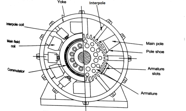
5) Armature Windings – These windings are arranged in armature slots, the slots are lined with tough insulating material. The useful EMF is encouraged in these findings and is received across brushes.
6) Commutator - It collects the current from armature and supplies to the load. It is cylindrical in shape. It periodically reverses the current direction between the rotor and external circuit. It is composed of multiple metal segments insulated from each other by thin layer of Mica. The number of segments is equal to number of armature coil.
7) Brushes and bearings - The brushes are usually made of carbon or graphite. The main function of brushes is to collect current from commutator. They are housed in brush holders and mounted on a spindle. The number of brushes per spindle depends upon the magnitude of the current to be collected from commutator.
Separately Excitation
It is the curve which relates the field current and armature terminal voltage on open circuit. For generating mode, we already know that generated emf is directly proportional to flux per pole and speed of armature.

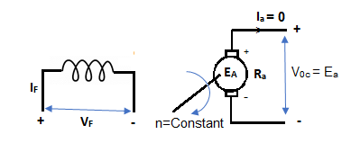
The circuit is given below-
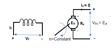
From above figure,
Voc = Ea
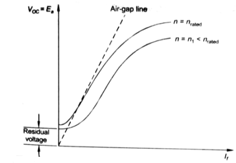
The magnetization characteristic of dc machines is determined by measuring Voc at rated armature speed and gradually increasing If from zero till Voc reaches above rated value of machine.
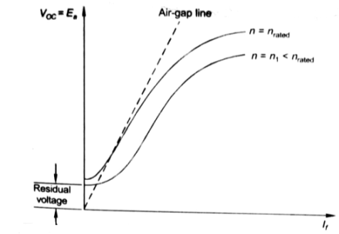
From above curve, we can conclude
1) A small residue voltage is present when field is unexcited.
2) The field current If increases from initial value, the flux and hence generated emf is increased.
3) The air-gap line is the magnetic behaviour of machines air-gap. The iron being unsaturated in this region consumes negligible power.
4) The open circuit cost is conducted by exciting the main field winding.
5) The equivalent main field current is given

Nf, main field turns
If, main field current
Nse, main series turn
Ise, main series current
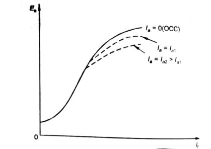
As induced emf is reduced by demagnetizing effect of armature reaction in saturation region of curve. So, the modified magnetization characteristics are shown below with Ia = 0, Ia = Ia1, Ia = Ia2.
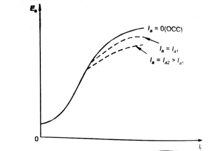
This is discussed in section 4.10
Armature Winding is the windings, in which voltage is induced. The Field Winding is the winding in which the main field flux is produced when the current through the winding is passed. Below section 4.5 deals with the types of armature windings.
Commutation:
The armature coil has two commutators connected to its ends. When commutators and brushes are in contact current transformation can be attained. In DC machines we use more than one coil. As shown in below figure.
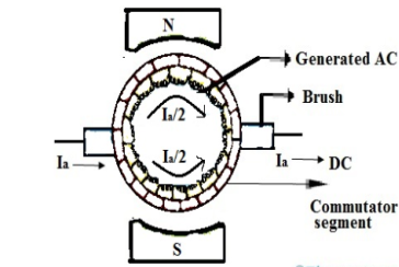
Fig: Commutation
Hence, we have more than one pair of commutator segments. The coil is short-circuited for a very short period of time with the help of brushes. This period is known as commutation period.
Reactance voltage: The coil in armature slot has self inductance L. As we already know the direction of current is reversed in commutation. So, due to reversal of current and self-inductance a voltage is induced equal to  . This voltage is also known as Reactance voltage.
Reactance voltage=
Tc= Commutation period.
I is maximum change in current in either direction.
So total change in current = I-(-I)=2I
Reactance voltage=
1.11 is form factor of sinusoidal waveform.
Armature windings
Simple lap winding –
1) In this type of winding, the back and front pitches are odd and opposite in sign. They have difference of 2 or multiple of 9r.
2) The back and front pitches should be equal to pole pitch.
3) Average pitch, 
4) Commutator pitch, Yc = ±m.
5) Resultant pitch, YR = YB – YF.
6) The number of slots is half the number of coil sides.
7) YB = YF ± 2m (m=1, simplex wave winding)
If YB> YF, YB = YF + 2 (Right handed winding). Yc = +1
If YB< YF, YB = YF – 2 (Left handed winding). Yc = -1.
8) They are useful for low voltage, high current generators.
Simple Wave Winding
1) The back and front pitches both are odd and of same sign.
2) YB and YF are nearly equal to the pole pitches.
3) Resultant pitch, YR = YB + YF
4) Commutator pitch, YC= YA (for lap winding YC = ±1).

5) Average pitch, 
6) The number of coils, 
7) The number of armature parallel paths =2m
m = multiplicity of windings.
8) They are suitable for low current and high voltage generators.
9) It gives more emf than lap winding.
Construction of commutator is already discussed in section 4.4
Linear commutation:
This type of commutation is also called as Ideal commutation. In this type of commutation the current from commutating coil changes linearly from +Ic to -Ic. The below figure shows the same.
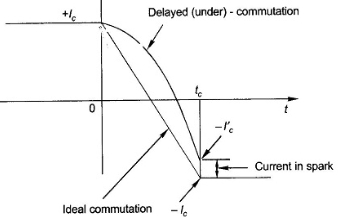
Fig: Ideal Commutation
There are two ways of achieving good commutation—close to straight-line commutation. These are resistance commutation and voltage commutation.
In a DC motor when the armature rotates the conductors also rotate and hence cut the flux. According to the law of electromagnetic induction, the induced EMF is in the opposite direction (by Fleming’s Right hand rule) to the applied voltage. As it has opposite direction so it is referred to as back EMF (Eb).
Let φ = Flux /pole
P = Number of poles
Total flux produced by poles = φ x P
Time taken to complete one revolution= 60/N
N= speed of armature conductor in rpm
Let e be the induced emf of the armature conductor.
By Faraday’s Law e=
Induced emf in one conductor is given as
E=
E= φPN/60
Z = total numbers of conductor
A = number of parallel paths
Then,
Z/A = number of conductors connected in series
We know that induced emf in each path is same across the line
Therefore,
Induced emf of DC generator
E = emf of one conductor × number of conductor connected in series.
Induced emf of DC generator is
E= φP x
x volts
volts
For Simple wave wound generator numbers of parallel paths are only 2. So, A=2
Therefore,
E= φP x
x =
= volts
volts
Simple lap-wound generator
Here, number of parallel paths is equal to number of conductors in one path
i.e. P = A
Therefore,
Induced emf for lap-wound generator is
Eg= x
x volts
volts
The back emf induced is motor is same as the emf induced in generator
Eb= x
x volts
volts
Q1) A 220V, 4-pole, wave wound dc series motor has 680 conductors on its armature. It has armature and series field resistance of 0.75 ohm. The motor takes a current of 40 A. Calculate the speed and torque developed if flux/pole is 25mWb?
Sol: Eb= x
x
Eb=V-IaRa=220-40x0.75=190 volts
190=25x10-3x680x40x(4/2)xN
N=502.9 rpm
Q2) A 4-pole 220V shunt motor has 540 lap wound conductors. It takes 32A from the supply mains. The field windings take 1A. The armature resistance is 0.09 ohm and flux/pole is 30mWb. Calculate speed.
Sol: Eb=V-IaRa
Ia=32-1=31 A
Eb= 220-0.09x31=217.2V
Eb= x
x
217.2=
N=804.4 rpm
Average conductor force
Fav = Bav l Ic
Bav = avg. Flux density over pole.
l = active conductor length.
Force, F = ZFav = BavlIcZ
T = f.r
T = Bav l IC Zr
r = mean of r gap radius.
Flux/pole = Bav
= Bav Pl
Pl


The torque is uniform for given flux/pole and armature current.
Q1) Determine torque established by the armature of six pole DC motor having 680 conductors, two paths in parallel, 24mWb flux/pole and armature current 50A?
Sol: 

T= x24x10-3x50x680x(4/2)=259.74 N-m
Q2) A 220V DC Shunt motor runs at 450rpm when armature current is 39A. Calculate speed if the torque is doubled. The armature has a resistance of 0.2 ohm?
Sol: Ta α φIa
Ta1 α φIa1 and Ta2 α φIa2
2= Ia2/39
Ia2=78A
N2/N1=Eb2/Eb1
Eb1=220-(39x0.2)=212.2Volts
Eb2=220-(78x0.2)=204.4Volts
N2/450=204.4/212.2
N2=433.46 rpm
Armature Reactions
When armature of a DC Machine carries current, the distributed armature winding produces its own mmf which is known as armature reaction. The figure is shown below.
The nature of armature reaction in a DC machine is cross magnetizing with its axis along the (90° to main pole).
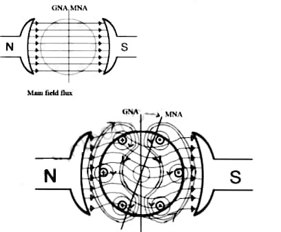
MNA (Magnetic Neutral Axis) It is the axis along which no EMF generated in the armature conductors.
GNA (Geometrical Neutral Axis) It is perpendicular to the field axis.
When DC machine is running the flux due to armature and field winding exists.The armature flux is dominant on the later and hence disturbing the main field flux. This effect is called armature reaction in DC machines.
Q. 1 A 4 pole, 210 V shunt motor has 450 lap wound conductor. It takes 32 A from supply mains and develops output power of 4.5 kW. The field takes 1 A. The armature resistance is 0.09 ohm and flux per pole is 30 mWb. Calculate speed and torque.
Soln. Ia = 32-1 = 31 n
Eb = V – Ia Ra = 210 - (0.09×31) = 207.21 V


N = 920.9 rpm


Q. 2 A 220 V, dc shunt motor has an armature resistance of 0.3 ohm and field resistance of 105 ohm. At no load speed is 1200 rpm and armature current is 2.3 A on application of rated load speed drops to 1120 rpm. Find the current and power input when motor delivers rated load.
Soln. N1 = 1200 rpm Eb1 = 220 – (0.3×2.3) = 219.31 V
N2 = 1120 rpm Eb2 = 220 – 0.3 Ia2


Ia2 = 37.93 A
Line current = Ia2 + Ish = 37.93 + (220/105) = 40 A
Power input = 220 × 40 = 8800 W
Q. 3 A 230 V shunt motor runs at 1000 rpm at no load and takes 6A. The total armature resistance is 0.2 ohm and field resistance is 210 ohm. Calculate the speed when loaded and taking 40 A. Assume flux constant.
Soln. 


Q. 4 The armature resistance of a 15 kW, 230 V series motor is 0? 1 ohm, the brush voltage drop is 3 V and series field resistance is 0.05 ohm. The motor takes 60 A speed is 600 rpm. Calculate speed when current is 100 A.
Soln.


Φ1  60
60
Φ2  100
100


N2=350.22 rpm
Q.5 A 230V DC Shunt motor takes 4A at no load when running at 600 rpm. The field resistance is 100 ohm. The resistance of armature at standstill gives a drop of 6V across armature terminals when 10A were passed through it. Find i)Speed at no load (ii) Torque. Normal input of motor is 6kW
Soln
i)Speed 
Ish=  =2.3A
=2.3A
F.L Power=6000
F.L line current=  =26.08A
Ia=26.08-2.3=23.78A
Ra= =0.6Ω
=0.6Ω


N=566.2 rpm
Ii)Torque Ta=  =
=

From the figure(a) below we can say For one pole pair with brushes placed in GNA which is also the MNA, when armature is not carrying current. In figure(b) the armature mmf distribution is shown. It is clearly seen that the armature mmf is stepped wave of 90 from d-axis. Which means its cross magnetizing. The step wave can be approximated as a triangular wave. The armature ampere turns will be
Ampere conductors/pole=ZIc/P=ZIa/AP
Ic=conductor current
Ampere turns/pole=ZIa/2AP=ATa(Peak)
ATa(peak)= ATa(Total)/P
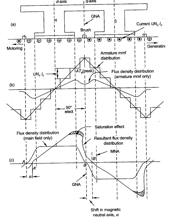
The flux density shown in figure(b) has a dip in q-axis because of large air gap in the inter-pole region. The Flux density of main field and the resultant flux density both are shown in figure(c). Where we can se that the armature reaction mmf distorts the flux density wave.so as to be depressed in one half of the pole and strengthen equally in other half. This is because of the odd symmetry with d-axis of the flux density wave of armature mmf. Due to this the flux/pole remains constant although the resultant flux density wave is distorted. The figure also shows that its MNA also gets shifted from its GNA by small angle α so that the brushes placed in GNA are no longer in MNA.
The armature reaction in DC machines is cross magnetizing causing distortion in flux density wave and slightly shifts MNA. It also causes demagnetization. Distortion in flux density distribution results in increase of flux density on one pole and decrease on other. Distortion also has adverse effect on commutation but can be solved by interpoles.
Unit – 4
DC MACHINES
They convert mechanical energy into electrical energy. The energy conversion is based on the principle of production of induced emf. The construction and working are explained below.
Construction – A simple generator is shown below, the essential parts of which are
1) Yoke – It is the outer frame of machine which carries the magnetic flux produced by poles and also provides mechanical support to the poles. The yoke is generally made of cast steel or rolled steel.
2) Pole shoes – They are made up of thin lamination of anmealed steel, which are piled up under hydraulic pressure. They spread out the flux in the air gap. They reduce the reluctance as they have large cross-sectional area.
3) Held coils –They are the copper wire which are wounded around the core, the flux is produced when the current passes through these coils.
4) Armature core – It provides the low reluctance path to the flux through the armature. It carries the conductor coils and makes them to rotate, which in turn tells the magnetic flux produced. It is cylindrical in shape and made of circular steel sheets.
5) Armature Windings – These windings are arranged in armature slots, the slots are lined with tough insulating material. The useful EMF is encouraged in these findings and is received across brushes.
6) Commutator - It collects the current from armature and supplies to the load. It is cylindrical in shape. It periodically reverses the current direction between the rotor and external circuit. It is composed of multiple metal segments insulated from each other by thin layer of Mica. The number of segments is equal to number of armature coil.
7) Brushes and bearings - The brushes are usually made of carbon or graphite. The main function of brushes is to collect current from commutator. They are housed in brush holders and mounted on a spindle. The number of brushes per spindle depends upon the magnitude of the current to be collected from commutator.
Separately Excitation
It is the curve which relates the field current and armature terminal voltage on open circuit. For generating mode, we already know that generated emf is directly proportional to flux per pole and speed of armature.

The circuit is given below-
From above figure,
Voc = Ea
The magnetization characteristic of dc machines is determined by measuring Voc at rated armature speed and gradually increasing If from zero till Voc reaches above rated value of machine.
From above curve, we can conclude
1) A small residue voltage is present when field is unexcited.
2) The field current If increases from initial value, the flux and hence generated emf is increased.
3) The air-gap line is the magnetic behaviour of machines air-gap. The iron being unsaturated in this region consumes negligible power.
4) The open circuit cost is conducted by exciting the main field winding.
5) The equivalent main field current is given

Nf, main field turns
If, main field current
Nse, main series turn
Ise, main series current
As induced emf is reduced by demagnetizing effect of armature reaction in saturation region of curve. So, the modified magnetization characteristics are shown below with Ia = 0, Ia = Ia1, Ia = Ia2.
This is discussed in section 4.10
Armature Winding is the windings, in which voltage is induced. The Field Winding is the winding in which the main field flux is produced when the current through the winding is passed. Below section 4.5 deals with the types of armature windings.
Commutation:
The armature coil has two commutators connected to its ends. When commutators and brushes are in contact current transformation can be attained. In DC machines we use more than one coil. As shown in below figure.
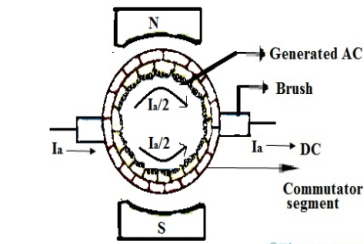
Fig: Commutation
Hence, we have more than one pair of commutator segments. The coil is short-circuited for a very short period of time with the help of brushes. This period is known as commutation period.
Reactance voltage: The coil in armature slot has self inductance L. As we already know the direction of current is reversed in commutation. So, due to reversal of current and self-inductance a voltage is induced equal to  . This voltage is also known as Reactance voltage.
Reactance voltage=
Tc= Commutation period.
I is maximum change in current in either direction.
So total change in current = I-(-I)=2I
Reactance voltage=
1.11 is form factor of sinusoidal waveform.
Armature windings
Simple lap winding –
1) In this type of winding, the back and front pitches are odd and opposite in sign. They have difference of 2 or multiple of 9r.
2) The back and front pitches should be equal to pole pitch.
3) Average pitch, 
4) Commutator pitch, Yc = ±m.
5) Resultant pitch, YR = YB – YF.
6) The number of slots is half the number of coil sides.
7) YB = YF ± 2m (m=1, simplex wave winding)
If YB> YF, YB = YF + 2 (Right handed winding). Yc = +1
If YB< YF, YB = YF – 2 (Left handed winding). Yc = -1.
8) They are useful for low voltage, high current generators.
Simple Wave Winding
1) The back and front pitches both are odd and of same sign.
2) YB and YF are nearly equal to the pole pitches.
3) Resultant pitch, YR = YB + YF
4) Commutator pitch, YC= YA (for lap winding YC = ±1).

5) Average pitch, 
6) The number of coils, 
7) The number of armature parallel paths =2m
m = multiplicity of windings.
8) They are suitable for low current and high voltage generators.
9) It gives more emf than lap winding.
Construction of commutator is already discussed in section 4.4
Linear commutation:
This type of commutation is also called as Ideal commutation. In this type of commutation the current from commutating coil changes linearly from +Ic to -Ic. The below figure shows the same.
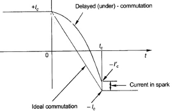
Fig: Ideal Commutation
There are two ways of achieving good commutation—close to straight-line commutation. These are resistance commutation and voltage commutation.
In a DC motor when the armature rotates the conductors also rotate and hence cut the flux. According to the law of electromagnetic induction, the induced EMF is in the opposite direction (by Fleming’s Right hand rule) to the applied voltage. As it has opposite direction so it is referred to as back EMF (Eb).
Let φ = Flux /pole
P = Number of poles
Total flux produced by poles = φ x P
Time taken to complete one revolution= 60/N
N= speed of armature conductor in rpm
Let e be the induced emf of the armature conductor.
By Faraday’s Law e=
Induced emf in one conductor is given as
E=
E= φPN/60
Z = total numbers of conductor
A = number of parallel paths
Then,
Z/A = number of conductors connected in series
We know that induced emf in each path is same across the line
Therefore,
Induced emf of DC generator
E = emf of one conductor × number of conductor connected in series.
Induced emf of DC generator is
E= φP x
x volts
volts
For Simple wave wound generator numbers of parallel paths are only 2. So, A=2
Therefore,
E= φP x
x =
= volts
volts
Simple lap-wound generator
Here, number of parallel paths is equal to number of conductors in one path
i.e. P = A
Therefore,
Induced emf for lap-wound generator is
Eg= x
x volts
volts
The back emf induced is motor is same as the emf induced in generator
Eb= x
x volts
volts
Q1) A 220V, 4-pole, wave wound dc series motor has 680 conductors on its armature. It has armature and series field resistance of 0.75 ohm. The motor takes a current of 40 A. Calculate the speed and torque developed if flux/pole is 25mWb?
Sol: Eb= x
x
Eb=V-IaRa=220-40x0.75=190 volts
190=25x10-3x680x40x(4/2)xN
N=502.9 rpm
Q2) A 4-pole 220V shunt motor has 540 lap wound conductors. It takes 32A from the supply mains. The field windings take 1A. The armature resistance is 0.09 ohm and flux/pole is 30mWb. Calculate speed.
Sol: Eb=V-IaRa
Ia=32-1=31 A
Eb= 220-0.09x31=217.2V
Eb= x
x
217.2=
N=804.4 rpm
Average conductor force
Fav = Bav l Ic
Bav = avg. Flux density over pole.
l = active conductor length.
Force, F = ZFav = BavlIcZ
T = f.r
T = Bav l IC Zr
r = mean of r gap radius.
Flux/pole = Bav
= Bav Pl
Pl


The torque is uniform for given flux/pole and armature current.
Q1) Determine torque established by the armature of six pole DC motor having 680 conductors, two paths in parallel, 24mWb flux/pole and armature current 50A?
Sol: 

T= x24x10-3x50x680x(4/2)=259.74 N-m
Q2) A 220V DC Shunt motor runs at 450rpm when armature current is 39A. Calculate speed if the torque is doubled. The armature has a resistance of 0.2 ohm?
Sol: Ta α φIa
Ta1 α φIa1 and Ta2 α φIa2
2= Ia2/39
Ia2=78A
N2/N1=Eb2/Eb1
Eb1=220-(39x0.2)=212.2Volts
Eb2=220-(78x0.2)=204.4Volts
N2/450=204.4/212.2
N2=433.46 rpm
Armature Reactions
When armature of a DC Machine carries current, the distributed armature winding produces its own mmf which is known as armature reaction. The figure is shown below.
The nature of armature reaction in a DC machine is cross magnetizing with its axis along the (90° to main pole).
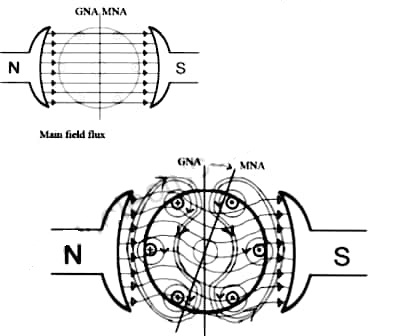
MNA (Magnetic Neutral Axis) It is the axis along which no EMF generated in the armature conductors.
GNA (Geometrical Neutral Axis) It is perpendicular to the field axis.
When DC machine is running the flux due to armature and field winding exists.The armature flux is dominant on the later and hence disturbing the main field flux. This effect is called armature reaction in DC machines.
Q. 1 A 4 pole, 210 V shunt motor has 450 lap wound conductor. It takes 32 A from supply mains and develops output power of 4.5 kW. The field takes 1 A. The armature resistance is 0.09 ohm and flux per pole is 30 mWb. Calculate speed and torque.
Soln. Ia = 32-1 = 31 n
Eb = V – Ia Ra = 210 - (0.09×31) = 207.21 V


N = 920.9 rpm


Q. 2 A 220 V, dc shunt motor has an armature resistance of 0.3 ohm and field resistance of 105 ohm. At no load speed is 1200 rpm and armature current is 2.3 A on application of rated load speed drops to 1120 rpm. Find the current and power input when motor delivers rated load.
Soln. N1 = 1200 rpm Eb1 = 220 – (0.3×2.3) = 219.31 V
N2 = 1120 rpm Eb2 = 220 – 0.3 Ia2


Ia2 = 37.93 A
Line current = Ia2 + Ish = 37.93 + (220/105) = 40 A
Power input = 220 × 40 = 8800 W
Q. 3 A 230 V shunt motor runs at 1000 rpm at no load and takes 6A. The total armature resistance is 0.2 ohm and field resistance is 210 ohm. Calculate the speed when loaded and taking 40 A. Assume flux constant.
Soln. 


Q. 4 The armature resistance of a 15 kW, 230 V series motor is 0? 1 ohm, the brush voltage drop is 3 V and series field resistance is 0.05 ohm. The motor takes 60 A speed is 600 rpm. Calculate speed when current is 100 A.
Soln.


Φ1  60
60
Φ2  100
100


N2=350.22 rpm
Q.5 A 230V DC Shunt motor takes 4A at no load when running at 600 rpm. The field resistance is 100 ohm. The resistance of armature at standstill gives a drop of 6V across armature terminals when 10A were passed through it. Find i)Speed at no load (ii) Torque. Normal input of motor is 6kW
Soln
i)Speed 
Ish=  =2.3A
=2.3A
F.L Power=6000
F.L line current=  =26.08A
Ia=26.08-2.3=23.78A
Ra= =0.6Ω
=0.6Ω


N=566.2 rpm
Ii)Torque Ta=  =
=

From the figure(a) below we can say For one pole pair with brushes placed in GNA which is also the MNA, when armature is not carrying current. In figure(b) the armature mmf distribution is shown. It is clearly seen that the armature mmf is stepped wave of 90 from d-axis. Which means its cross magnetizing. The step wave can be approximated as a triangular wave. The armature ampere turns will be
Ampere conductors/pole=ZIc/P=ZIa/AP
Ic=conductor current
Ampere turns/pole=ZIa/2AP=ATa(Peak)
ATa(peak)= ATa(Total)/P
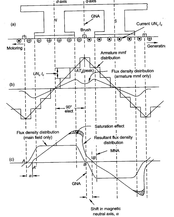
The flux density shown in figure(b) has a dip in q-axis because of large air gap in the inter-pole region. The Flux density of main field and the resultant flux density both are shown in figure(c). Where we can se that the armature reaction mmf distorts the flux density wave.so as to be depressed in one half of the pole and strengthen equally in other half. This is because of the odd symmetry with d-axis of the flux density wave of armature mmf. Due to this the flux/pole remains constant although the resultant flux density wave is distorted. The figure also shows that its MNA also gets shifted from its GNA by small angle α so that the brushes placed in GNA are no longer in MNA.
The armature reaction in DC machines is cross magnetizing causing distortion in flux density wave and slightly shifts MNA. It also causes demagnetization. Distortion in flux density distribution results in increase of flux density on one pole and decrease on other. Distortion also has adverse effect on commutation but can be solved by interpoles.