UNIT 4
KINETICS OF RIGID BODY
Start from the expression of the angular momentum of a system of particles about the center of mass,  ,
,
 (1)
(1)
 (2)
(2)

Here, r is the position vector relative to the center of mass; v is the velocity relative to the center of mass. We note that, in the above expression, an integral is used instead of a summation, since we are now dealing with a continuum distribution of mass.
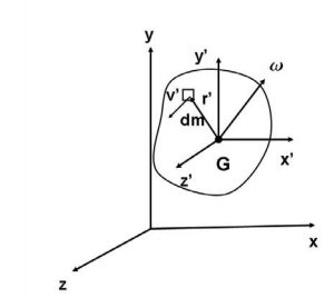
For a 3D rigid body, the distance between any particle and the center of mass will remain constant, and the particle velocity, relative to the center of mass, will be given by

Thus we have,

Here, we have used the vector identity A ×( B ×C) = (A·C)B −(A·B)C. We note that, for planar bodies undergoing a 2D motion in its own plane, r is perpendicular to ω, and the term (r ·ω) is zero. In this case, the vectors ω and HG are always parallel. In the three-dimensional case however, this simplification does not occur, and as a consequence, the angular velocity vector, ω, and the angular momentum vector, HG, are in general, not parallel. In Cartesian coordinates, we have, and
and  , and the above expression can be expanded to yield,

 +
+ +
+
The quantities Ixx, Iyy, and Izz are called moments of inertia with respect to the x, y and z axis, respectively, and are given by
 ,
,  ,
,  .
.
We observe that the quantity in the integrand is precisely the square of the distance to the x, y and z axis, respectively. They are analogous to the moment of inertia used in the two dimensional case. It is also clear, from their expressions, that the moments of inertia are always positive. The quantities Ixy, Ixz, Iyx, Iyz, Izx and Izy are called products of inertia. They can be positive, negative, or zero, and are given by,
 ,
,  ,
,  .
.
They are a measure of the imbalance in the mass distribution. If we are interested in calculating the angular momentum with respect to a fixed point O then, the resulting expression would be,


Here the moments of products of inertial have expressions which are analogous to those given but with  replace by x, y and z. Thus we have that
 ,
,  ,
,  ,
,
 ,
,  ,
,
 ,
,
The expression for angular momentum given by equation (3), can be written in matrix form as


Where [IG] is the tensor of inertia (written in matrix form) about the centre of mass G and with respect to the xyz axes. The tensor of inertia gives us an idea about how the mass is distributed in a rigid body. Analogously, we can define the tensor of inertia about point O, by writing equation (4) in matrix form.
Thus, we have HO = [IO] ω
Where the components of [IO] are the moments and products of inertia about point O given above. It follows from the definition of the products of inertia, that the tensors of inertia are always symmetric.
The implications of equation (5) are that in many situations of importance, even for bodes of some symmetry, the angular momentum vector  and the angular velocity vector
  are not parallel. This introduces considerable complexity into the analysis of the dynamics of rotating bodies in three dimensions.
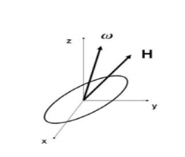
For a general three-dimensional body, it is always possible to find 3 mutually orthogonal axis (an x, y, z coordinate system) for which the products of inertia are zero, and the inertia matrix takes a diagonal form. In most problems, this would be the preferred system in which to formulate a problem. For a rotation about only one of these axis, the angular momentum vector is parallel to the angular velocity vector. For symmetric bodies, it may be obvious which axis is principle axis. However, for an irregular-shaped body this coordinate system may be difficult to determine by inspection; we will present a general method to determine these axes in the next section. But, if the body has symmetries with respect to some of the axis, then some of the products of inertia become zero and we can identify the principal axes.
For instance, if the body is symmetric with respect to the plane  then, we will have
  and
and  will be a principal axis. This can be shown by looking at the definition of the products of inertia.

The integral for, say,  can be decomposed into two integrals for the two halves of the body at either side of the plane
 . The integrand on one half
  will be equal in magnitude and opposite in sign to the integrand on the other half (because
  will change sign). Therefore, the integrals over the two halves will cancel each other and the product of inertia
  will be zero. (As will the product of inertia
  ) Also, if the body is symmetric with respect to two planes passing through the center of mass which are orthogonal to the coordinate axis, then the tensor of inertia is diagonal, with
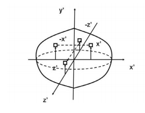
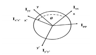
Another case of practical importance is when we consider axisymmetric bodies of revolution. In this case, if one of the axis coincides with the axis of symmetry, the tensor of inertia has a simple diagonal form. For an axisymmetric body, the moments of inertia about the two axis in the plane will be equal. Therefore, the moment about any axis in this plane is equal to one of these. And therefore, any axis in the plane is a principal axis. One can extend this to show that if the moment of inertia is equal about two axis in the plane (IP P = Ixx), whether or not they are orthogonal, then all axes in the plane are principal axes and the moment of inertia is the same about all of them. In its inertial properties, the body behaves like a circular cylinder.
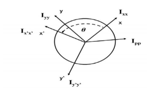
The tensor of inertia will take different forms when expressed in different axes. When the axes are such that the tensor of inertia is diagonal, then these axes are called the principal axes of inertia.
The Search for Principal Axes and Moments of Inertia as an Eigenvalue Problem
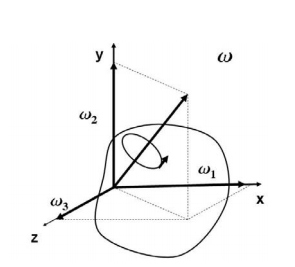
Three orthogonal principal axes of inertia always exist even though in bodies without symmetries their directions may not be obvious. To find the principle axis of a general body consider the body shown in the figure that rotates about an unknown principal axis. The total angular momentum vector is  in the direction of the principle axis. For rotation about the principal axis, the angular momentum and the angular velocity are in the same direction.
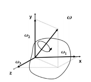
We seek a coordinate axes x, y and z, about which a rotation ωx, ωy and ωz, which is aligned with this coordinate direction, will be parallel to the angular momentum vector and related by the equation
 (7)
(7)
We then express the general form for angular momentum vector in components along the x, y and z axis in term of the components of ω along these axes using the general form of the inertia tensor in the x, y, z system, we have
 (8)
(8)
To obtain the special direction of ω that is aligned with a principal axis, we equate two expressions
 (9)
(9)
At this point in the process we know the inertia tensor in an arbitrary x, y, and z system and are seeking the special orientation of ω which will align the angular momentum HG with the angular velocity ω. Collecting terms from equation(11) on the left-hand side, we obtain
 (10)
(10)
Resulting in the requirement that
 (11)
(11)
The structure of the solution for finding the principal axes of inertia and their magnitudes is a characteristic value problem. The three eigenvalues give the directions of the three principal axis, and the three eigenvectors give the moments of inertia with respect to each of these axis. In principal directions, the inertia tensor has the form

 and
and  =
= Also, in principal axes we will then have

Parallel axes theorem
Parallel axis theorem states that the moment of inertia of a body about an axis parallel to the body passing through its center is equal to the sum of moment of inertia of body about the axis passing through the centre and product of mass of the body times the square of distance between the two axes.
Parallel Axis Theorem Formula
Parallel axis theorem statement can be expressed as follows:
I = Ic + Mh2
Where,
- I is the moment of inertia of the body
- Ic is the moment of inertia about the centre
- M is the mass of the body
- h2 is the square of the distance between the two axes
Parallel Axis Theorem Derivation
Let Ic be the moment of inertia of an axis which is passing through the center of mass (AB from the figure) and I be the moment of inertia about the axis A’B’ at a distance of h.
Consider a particle of mass m at a distance r from the center of gravity of the body.
Then,
Distance from A’B’ = r + h
I = ∑m (r + h)2
I = ∑m (r2 + h2 + 2rh)
I = ∑mr2 + ∑mh2 + ∑2rh
I = Ic + h2∑m + 2h∑mr
I = Ic + Mh2 + 0
I = Ic + Mh2
Hence the above theorem is of parallel axes theorem.
Theorem of perpendicular axes
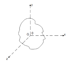
It states that , if  be the moments of inertia of figure or plane section about two axis x and y which are perpendicular to each other at point O, then moment of Inertia of that plane section about Z axis which is perpendicular to the plane [&(
 is given by :

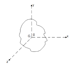
 of plane area about Z axis passing through C.G.
 of plane area about X axis passing through C.G
 of plane area about Y axis passing through C.G
 Is also called as polar moment of Inertia (J)
Moment Of Inertia of Cylinder
The moment of inertia of cylinder about a perpendicular axis passing through its centre is determined by;
Ix = ¼ MR2 + 1/12 ML2
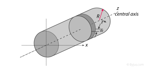
We will look at the derivation of this formula below.
Generally, the derivation involves 3 primary steps. It includes;
- Splitting the cylinder into infinitesimally thin disks and stating the moment of inertia.
- Using both parallel and perpendicular axis theorems to determine the expression.
- Integrating over the length of the cylinder.
1. Cutting the cylinder into infinitesimally thin disks
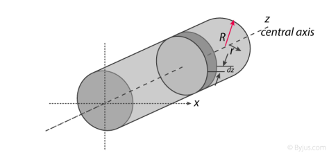
We will consider the cylinder having mass M, radius R, length L and the z-axis which passes through the central axis.
Here,
Density ρ = M / V
Next, we will consider the moment of inertia of the infinitesimally thin disks with thickness dz.
First, we assume that dm is the mass of each disk, We get;
Dm = ρ X Volume of disk
Dm = M / V X (πr2.dz)
We take V = area of circular face X length which is = πr2L. Now we obtain;
Dm = M / πr2L X (πr2.dz)
Dm = M / L X dz
The moment of inertia about the central axis is given as;
Dlz = ½ dmR2
Use of Perpendicular Axis Theorem
We now apply the perpendicular axis theorem which gives us;
Dlz = dlx + dly
Here, if we need to consider that both x and y moments of inertia are equal by symmetry.
Dlx = dly
We need to combine the equations for the perpendicular axis theorem and symmetry. We get;
Dlx = dlz / 2
Now we substitute lz from the equation above.
Dlx = ½ x ½ dmR2
Dlx = ¼ dmR2
Alternatively, for the x-axis, we use the parallel axis theorem to find the moment of inertia. We get;
Dlx = ¼ dmR2 + dmz2
Integration
Now we conduct integration over the length of the cylinder to express the mass element dm in terms of z. We take the integral from z=0 to z=L.
Ix = o∫L dlx
Ix = o∫L ¼ dzR2 + o∫L ¼ z2 m / l dz
Ix = ¼ M / L R2z + M / L Z3 / 3]0L
Since it is a definite form of integral we ignore the constant. We will now have;
Ix = ¼ M / L R2 L + M / 3L 2L3 / 23
Ix = ¼ MR2 + 1/12 ML2


Similarly, 
As the centroidal axis coincides with axis of cylinder.


Therefore, I =1/2 MR2
Moment Of Inertia of Sphere
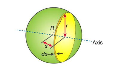
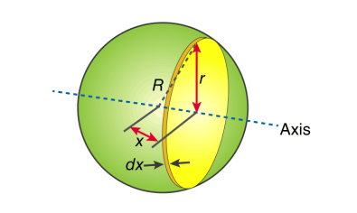
First, we take the moment of inertia of a disc that is thin. It is given as;
I = ½ MR2
In this case, we write it as;
DI (infinitesimally moment of inertia element) = ½ r2dm
Find the dm and dv using;
Dm = p dV
p = moment of a thin disk of mass dm
Dv = expressing mass dm in terms of density and volume
DV = π r2 dx
Now we replace dV into dm. We get;
Dm = p π r2 dx
And finally, we replace dm with dI.
DI = ½ p π r4 dx
The next step involves adding x to the equation. If we look at the diagram we see that r, R and x forms a triangle. Now we will use Pythagoras theorem which gives us;
r2 = R2 – x2
Now if we substitute the values we get;
DI = ½ p π (R2 – x2)2 dx
This leads to:
I = ½ p π -R∫R (R2 – x2)2 dx
After integration and expanding we get;
I = pπ 8/15 R5
Additionally, we have to find the density as well. For that we use;
P (density) = M (mass) / V (volume)
p = M (mass) / (4/3 πR3)
If we substitute all the values;
I = 8/15 π [M / (4/3 πR3)] R5
I = ⅖ MR2
Moment of inertia of Solid Cone
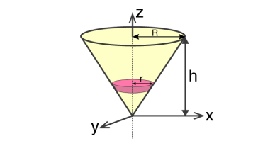
We will take a solid cone where its axis will pass through the centre with radius = r, height = h. We will need to determine the mass though.
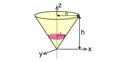
We take the elemental disc whose mass is given by;
Dm = ρ ⋅ π r2dz
Density is given as;
ρ = M / V = M / (⅓ π R2h)
With this, we will calculate the dm.
Dm = [M / (⅓ π R2h)] X π r2dz
Dm = (3M / R2h ) X r2dz
If we consider the similarity of the triangle, then we have;
R / r = h / z
r = R .z / h
Now,
Dm = (3M / R2h )⋅( R2 / h2) ⋅ z2dz
Dm = (3M / h3 ). z2dz
If we consider z-axis, the moment of inertia of the elemental disk will be;
DI = ½ dmr2
DI = ½ ⋅ (3M / h3 ) . z2 ⋅ (z2 R2 / h2) dz
DI = 3 / 2 ⋅ M R2 / h5 X z4dz
Now we will follow the integration process. Here;
I = 3 / 2 ⋅ M R2 / h5 o∫h z4dz
I = 3 / 2 ⋅ M R2 / h5 [z5 / 5 ]oh
I = 3 / 2 ⋅ M R2 / h5 ⋅ h5 / 5
Therefore, I = 3/10 MR2
Moments of Inertia for Areas:
When a distributed loading whose intensity varies linearly acts perpendicular to an area, the computation of the moment of the loading distribution about an axis involves a quantity called the moment of inertia of the area or simply area moment of inertia.
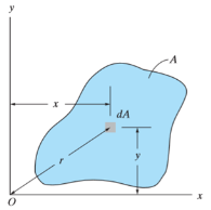
Consider a differential plate, subjected to fluid pressure P that varies linearly with depth, as shown in fig, such that  , where,
  is the specific weight of fluid.
The force acting on a acting on the differential area of the plate is given by

The moment of this this force about the x-axis is

Integrating  over the entire area of the plate yields


The integral part of the moment equation is called area moment of inertia about x-axis 

Similarly, area moment of inertia about y-axis is given as,

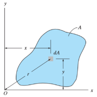
Moment of Inertia for area can also be given as

Where, A is the total area
And k is referred as radius of gyration
Radius of gyration for area of a plate about an axis is defined as the radial distance to a point which would have a same moment of inertia as the plate’s actual distribution of area, if the total area of the plate were concentrated.
It is given by,

Polar Moment Of Inertia
Polar Moment of Inertia is a measure of an object’s capacity to oppose or resist torsion when some amount of torque is applied to it on a specified axis. Torsion, on the other hand, is nothing but the twisting of an object due to an applied torque. Polar moment of inertia basically describes the cylindrical object’s (including its segments) resistance to torsional deformation when torque is applied in a plane that is parallel to the cross-section area or in a plane that is perpendicular to the object’s central axis.
If we put it in simple terms polar moment of inertia is the resistance offered by a beam or shaft when it is being distorted by torsion. This opposition usually arises from the cross-sectional area and it should be noted that it does not depend on the material composition. If the polar moment of inertia is of higher magnitude then the torsional resistance of the object will also be greater. More torque will be required to turn the shaft at an angle.
Nonetheless, it is one of the main aspects of the area moment of inertia and we can use the perpendicular axis theorem to link the two quantities.
Polar Moment Of Inertia Formula
Polar Moment of Inertia is also called the second polar moment of area. It is usually denoted by IZ. However, sometimes J or JZ is also used. Polar Moment of Inertia can be represented mathematically with the given formula;
I or J = r2 dA
Here,
r = distance to the element dA.
Units
The dimension unit of polar moment of inertia is length to the power of four (L4); The SI unit of this property is, meters to the fourth power (m4). In the imperial unit system, it is inches to the fourth power (in4).
Types of Cross-section Polar Moment of Inertia
There are three main types of cross-section polar moment of inertia. They are as follows.

1. Hollow Shaft
To determine the polar moment of inertia we use;
Jhollow = π (R04–R14 )/2
R1 and Ro = inner and outer radius of the hollow shaft.
2. Thin-Walled Shaft
To determine the polar moment of inertia we use;
Jthin = 2πt [R0+Ri /2]3
t = thickness of the thin-walled shaft.
3. Solid Circular Shaft
To determine the polar moment of inertia we use the following formula;
Jsolid = πR4 /2
R = radius of the circular shaft.
Uses and Limitations
Generally, the second polar moment of area is used in determining the angular displacement of a body that is subjected to torque or to calculate the torsion force on a circular body. As for the limitation, the polar moment of inertia is not suitable for analyzing shafts and beams with non-circular cross-sections. This is mainly because objects with non-circular cross-sections tend to warp when torque is applied and it further leads to out-of-plane deformations.
The Moment of a force is a measure of its tendency to cause a body to rotate about a specific point or axis. This is different from the tendency for a body to move, or translate, in the direction of the force. In order for a moment to develop, the force must act upon the body in such a manner that the body would begin to twist. This occurs every time a force is applied so that it does not pass through the centroid of the body. A moment is due to a force not having an equal and opposite force directly along it's line of action.
Imagine two people pushing on a door at the doorknob from opposite sides. If both of them are pushing with an equal force then there is a state of equilibrium. If one of them would suddenly jump back from the door, the push of the other person would no longer have any opposition and the door would swing away. The person who was still pushing on the door created a moment.
Elements of a Moment
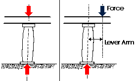
The magnitude of the moment of a force acting about a point or axis is directly proportional to the distance of the force from the point or axis. It is defined as the product of the force (F) and the moment arm (d). The moment arm or lever arm is the perpendicular distance between the line of action of the force and the center of moments.
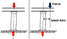
Moment = Force x Distance or M = (F)(d)
The Center of Moments may be the actual point about which the force causes rotation. It may also be a reference point or axis about which the force may be considered as causing rotation. It does not matter as long as a specific point is always taken as the reference point. The latter case is much more common situation in structural design problems.
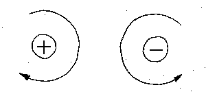
A moment is expressed in units of foot-pounds, kip-feet, newton-meters, or kilo newton-meters. A moment also has a sense; A clockwise rotation about the center of moments will be considered a positive moment; while a counter-clockwise rotation about the center of moments will be considered negative. The most common way to express a moment is
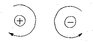
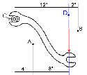
The example shows a wrench being applied to a nut. A 100 pound force is applied to it at point C, the center of the nut. The force is applied at an x- distance of 12 inches from the nut. The center of moments could be point C, but could also be points A or B or D.
Moment about C
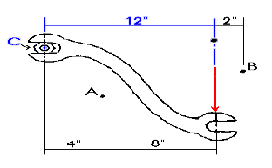
The moment arm for calculating the moment around point C is 12 inches. The magnitude of the moment about point C is 12 inches multiplied by the force of 100 lbs to give a total moment of 1200 inch-lbs (or 100 ft-lbs).
Moment Arm (d) = 12 inches
Magnitude (F) = 100 lbs
Moment = M = 100 lbs x 12 in. = 1200 in-lbs
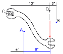
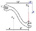
Similarly, we can find the moments about any point in space.
Moment @ | A | B | D |
Moment Arm | 8 inches | 2 inches | 0 inches |
Magnitude of F | 100 pounds | 100 pounds | 100 pounds |
Total Moment | 800 in- pounds | 200 in- pounds | 0 in- pounds |
|
 |
 |
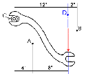 |
A moment causes a rotation about a point or axis. If the moment is to be taken about a point due to a force F, then in order for a moment to develop, the line of action cannot pass through that point. If the line of action does go through that point, the moment is zero because the magnitude of the moment arm is zero. Such was the case for point D in the previous wrench problem. The total moment was zero because the moment arm was zero as well.
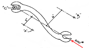
As another example, let us assume that 200 pound force is applied to the wrench as indicated. The moment of the 200 pound force applied at C is zero because:
M = F x d = 200 lbs x 0 in = 0 in-lbs
In other words, there is no tendency for the 200 pound force to cause the wrench to rotate the nut. One could increase the magnitude of the force until the bolt finally broke off (shear failure).
The moment about points X, Y, and Z would also be zero because they also lie on the line of action.
UNIT 4
KINETICS OF RIGID BODY
Start from the expression of the angular momentum of a system of particles about the center of mass,  ,
,
 (1)
(1)
 (2)
(2)

Here, r is the position vector relative to the center of mass; v is the velocity relative to the center of mass. We note that, in the above expression, an integral is used instead of a summation, since we are now dealing with a continuum distribution of mass.
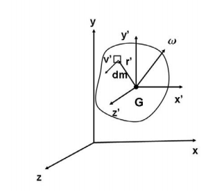
For a 3D rigid body, the distance between any particle and the center of mass will remain constant, and the particle velocity, relative to the center of mass, will be given by

Thus we have,

Here, we have used the vector identity A ×( B ×C) = (A·C)B −(A·B)C. We note that, for planar bodies undergoing a 2D motion in its own plane, r is perpendicular to ω, and the term (r ·ω) is zero. In this case, the vectors ω and HG are always parallel. In the three-dimensional case however, this simplification does not occur, and as a consequence, the angular velocity vector, ω, and the angular momentum vector, HG, are in general, not parallel. In Cartesian coordinates, we have, and
and  , and the above expression can be expanded to yield,

 +
+ +
+
The quantities Ixx, Iyy, and Izz are called moments of inertia with respect to the x, y and z axis, respectively, and are given by
 ,
,  ,
,  .
.
We observe that the quantity in the integrand is precisely the square of the distance to the x, y and z axis, respectively. They are analogous to the moment of inertia used in the two dimensional case. It is also clear, from their expressions, that the moments of inertia are always positive. The quantities Ixy, Ixz, Iyx, Iyz, Izx and Izy are called products of inertia. They can be positive, negative, or zero, and are given by,
 ,
,  ,
,  .
.
They are a measure of the imbalance in the mass distribution. If we are interested in calculating the angular momentum with respect to a fixed point O then, the resulting expression would be,


Here the moments of products of inertial have expressions which are analogous to those given but with  replace by x, y and z. Thus we have that
 ,
,  ,
,  ,
,
 ,
,  ,
,
 ,
,
The expression for angular momentum given by equation (3), can be written in matrix form as


Where [IG] is the tensor of inertia (written in matrix form) about the centre of mass G and with respect to the xyz axes. The tensor of inertia gives us an idea about how the mass is distributed in a rigid body. Analogously, we can define the tensor of inertia about point O, by writing equation (4) in matrix form.
Thus, we have HO = [IO] ω
Where the components of [IO] are the moments and products of inertia about point O given above. It follows from the definition of the products of inertia, that the tensors of inertia are always symmetric.
The implications of equation (5) are that in many situations of importance, even for bodes of some symmetry, the angular momentum vector  and the angular velocity vector
  are not parallel. This introduces considerable complexity into the analysis of the dynamics of rotating bodies in three dimensions.
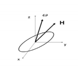
For a general three-dimensional body, it is always possible to find 3 mutually orthogonal axis (an x, y, z coordinate system) for which the products of inertia are zero, and the inertia matrix takes a diagonal form. In most problems, this would be the preferred system in which to formulate a problem. For a rotation about only one of these axis, the angular momentum vector is parallel to the angular velocity vector. For symmetric bodies, it may be obvious which axis is principle axis. However, for an irregular-shaped body this coordinate system may be difficult to determine by inspection; we will present a general method to determine these axes in the next section. But, if the body has symmetries with respect to some of the axis, then some of the products of inertia become zero and we can identify the principal axes.
For instance, if the body is symmetric with respect to the plane  then, we will have
  and
and  will be a principal axis. This can be shown by looking at the definition of the products of inertia.
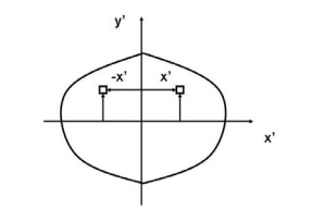
The integral for, say,  can be decomposed into two integrals for the two halves of the body at either side of the plane
 . The integrand on one half
  will be equal in magnitude and opposite in sign to the integrand on the other half (because
  will change sign). Therefore, the integrals over the two halves will cancel each other and the product of inertia
  will be zero. (As will the product of inertia
  ) Also, if the body is symmetric with respect to two planes passing through the center of mass which are orthogonal to the coordinate axis, then the tensor of inertia is diagonal, with

Another case of practical importance is when we consider axisymmetric bodies of revolution. In this case, if one of the axis coincides with the axis of symmetry, the tensor of inertia has a simple diagonal form. For an axisymmetric body, the moments of inertia about the two axis in the plane will be equal. Therefore, the moment about any axis in this plane is equal to one of these. And therefore, any axis in the plane is a principal axis. One can extend this to show that if the moment of inertia is equal about two axis in the plane (IP P = Ixx), whether or not they are orthogonal, then all axes in the plane are principal axes and the moment of inertia is the same about all of them. In its inertial properties, the body behaves like a circular cylinder.
The tensor of inertia will take different forms when expressed in different axes. When the axes are such that the tensor of inertia is diagonal, then these axes are called the principal axes of inertia.
The Search for Principal Axes and Moments of Inertia as an Eigenvalue Problem
Three orthogonal principal axes of inertia always exist even though in bodies without symmetries their directions may not be obvious. To find the principle axis of a general body consider the body shown in the figure that rotates about an unknown principal axis. The total angular momentum vector is  in the direction of the principle axis. For rotation about the principal axis, the angular momentum and the angular velocity are in the same direction.
We seek a coordinate axes x, y and z, about which a rotation ωx, ωy and ωz, which is aligned with this coordinate direction, will be parallel to the angular momentum vector and related by the equation
 (7)
(7)
We then express the general form for angular momentum vector in components along the x, y and z axis in term of the components of ω along these axes using the general form of the inertia tensor in the x, y, z system, we have
 (8)
(8)
To obtain the special direction of ω that is aligned with a principal axis, we equate two expressions
 (9)
(9)
At this point in the process we know the inertia tensor in an arbitrary x, y, and z system and are seeking the special orientation of ω which will align the angular momentum HG with the angular velocity ω. Collecting terms from equation(11) on the left-hand side, we obtain
 (10)
(10)
Resulting in the requirement that
 (11)
(11)
The structure of the solution for finding the principal axes of inertia and their magnitudes is a characteristic value problem. The three eigenvalues give the directions of the three principal axis, and the three eigenvectors give the moments of inertia with respect to each of these axis. In principal directions, the inertia tensor has the form

 and
and  =
= Also, in principal axes we will then have

Parallel axes theorem
Parallel axis theorem states that the moment of inertia of a body about an axis parallel to the body passing through its center is equal to the sum of moment of inertia of body about the axis passing through the centre and product of mass of the body times the square of distance between the two axes.
Parallel Axis Theorem Formula
Parallel axis theorem statement can be expressed as follows:
I = Ic + Mh2
Where,
- I is the moment of inertia of the body
- Ic is the moment of inertia about the centre
- M is the mass of the body
- h2 is the square of the distance between the two axes
Parallel Axis Theorem Derivation
Let Ic be the moment of inertia of an axis which is passing through the center of mass (AB from the figure) and I be the moment of inertia about the axis A’B’ at a distance of h.
Consider a particle of mass m at a distance r from the center of gravity of the body.
Then,
Distance from A’B’ = r + h
I = ∑m (r + h)2
I = ∑m (r2 + h2 + 2rh)
I = ∑mr2 + ∑mh2 + ∑2rh
I = Ic + h2∑m + 2h∑mr
I = Ic + Mh2 + 0
I = Ic + Mh2
Hence the above theorem is of parallel axes theorem.
Theorem of perpendicular axes
It states that , if  be the moments of inertia of figure or plane section about two axis x and y which are perpendicular to each other at point O, then moment of Inertia of that plane section about Z axis which is perpendicular to the plane [&(
 is given by :

 of plane area about Z axis passing through C.G.
 of plane area about X axis passing through C.G
 of plane area about Y axis passing through C.G
 Is also called as polar moment of Inertia (J)
Moment Of Inertia of Cylinder
The moment of inertia of cylinder about a perpendicular axis passing through its centre is determined by;
Ix = ¼ MR2 + 1/12 ML2
We will look at the derivation of this formula below.
Generally, the derivation involves 3 primary steps. It includes;
- Splitting the cylinder into infinitesimally thin disks and stating the moment of inertia.
- Using both parallel and perpendicular axis theorems to determine the expression.
- Integrating over the length of the cylinder.
1. Cutting the cylinder into infinitesimally thin disks
We will consider the cylinder having mass M, radius R, length L and the z-axis which passes through the central axis.
Here,
Density ρ = M / V
Next, we will consider the moment of inertia of the infinitesimally thin disks with thickness dz.
First, we assume that dm is the mass of each disk, We get;
Dm = ρ X Volume of disk
Dm = M / V X (πr2.dz)
We take V = area of circular face X length which is = πr2L. Now we obtain;
Dm = M / πr2L X (πr2.dz)
Dm = M / L X dz
The moment of inertia about the central axis is given as;
Dlz = ½ dmR2
Use of Perpendicular Axis Theorem
We now apply the perpendicular axis theorem which gives us;
Dlz = dlx + dly
Here, if we need to consider that both x and y moments of inertia are equal by symmetry.
Dlx = dly
We need to combine the equations for the perpendicular axis theorem and symmetry. We get;
Dlx = dlz / 2
Now we substitute lz from the equation above.
Dlx = ½ x ½ dmR2
Dlx = ¼ dmR2
Alternatively, for the x-axis, we use the parallel axis theorem to find the moment of inertia. We get;
Dlx = ¼ dmR2 + dmz2
Integration
Now we conduct integration over the length of the cylinder to express the mass element dm in terms of z. We take the integral from z=0 to z=L.
Ix = o∫L dlx
Ix = o∫L ¼ dzR2 + o∫L ¼ z2 m / l dz
Ix = ¼ M / L R2z + M / L Z3 / 3]0L
Since it is a definite form of integral we ignore the constant. We will now have;
Ix = ¼ M / L R2 L + M / 3L 2L3 / 23
Ix = ¼ MR2 + 1/12 ML2


Similarly, 
As the centroidal axis coincides with axis of cylinder.


Therefore, I =1/2 MR2
Moment Of Inertia of Sphere
First, we take the moment of inertia of a disc that is thin. It is given as;
I = ½ MR2
In this case, we write it as;
DI (infinitesimally moment of inertia element) = ½ r2dm
Find the dm and dv using;
Dm = p dV
p = moment of a thin disk of mass dm
Dv = expressing mass dm in terms of density and volume
DV = π r2 dx
Now we replace dV into dm. We get;
Dm = p π r2 dx
And finally, we replace dm with dI.
DI = ½ p π r4 dx
The next step involves adding x to the equation. If we look at the diagram we see that r, R and x forms a triangle. Now we will use Pythagoras theorem which gives us;
r2 = R2 – x2
Now if we substitute the values we get;
DI = ½ p π (R2 – x2)2 dx
This leads to:
I = ½ p π -R∫R (R2 – x2)2 dx
After integration and expanding we get;
I = pπ 8/15 R5
Additionally, we have to find the density as well. For that we use;
P (density) = M (mass) / V (volume)
p = M (mass) / (4/3 πR3)
If we substitute all the values;
I = 8/15 π [M / (4/3 πR3)] R5
I = ⅖ MR2
Moment of inertia of Solid Cone
We will take a solid cone where its axis will pass through the centre with radius = r, height = h. We will need to determine the mass though.
We take the elemental disc whose mass is given by;
Dm = ρ ⋅ π r2dz
Density is given as;
ρ = M / V = M / (⅓ π R2h)
With this, we will calculate the dm.
Dm = [M / (⅓ π R2h)] X π r2dz
Dm = (3M / R2h ) X r2dz
If we consider the similarity of the triangle, then we have;
R / r = h / z
r = R .z / h
Now,
Dm = (3M / R2h )⋅( R2 / h2) ⋅ z2dz
Dm = (3M / h3 ). z2dz
If we consider z-axis, the moment of inertia of the elemental disk will be;
DI = ½ dmr2
DI = ½ ⋅ (3M / h3 ) . z2 ⋅ (z2 R2 / h2) dz
DI = 3 / 2 ⋅ M R2 / h5 X z4dz
Now we will follow the integration process. Here;
I = 3 / 2 ⋅ M R2 / h5 o∫h z4dz
I = 3 / 2 ⋅ M R2 / h5 [z5 / 5 ]oh
I = 3 / 2 ⋅ M R2 / h5 ⋅ h5 / 5
Therefore, I = 3/10 MR2
Moments of Inertia for Areas:
When a distributed loading whose intensity varies linearly acts perpendicular to an area, the computation of the moment of the loading distribution about an axis involves a quantity called the moment of inertia of the area or simply area moment of inertia.
Consider a differential plate, subjected to fluid pressure P that varies linearly with depth, as shown in fig, such that  , where,
  is the specific weight of fluid.
The force acting on a acting on the differential area of the plate is given by

The moment of this this force about the x-axis is

Integrating  over the entire area of the plate yields


The integral part of the moment equation is called area moment of inertia about x-axis 

Similarly, area moment of inertia about y-axis is given as,

Moment of Inertia for area can also be given as

Where, A is the total area
And k is referred as radius of gyration
Radius of gyration for area of a plate about an axis is defined as the radial distance to a point which would have a same moment of inertia as the plate’s actual distribution of area, if the total area of the plate were concentrated.
It is given by,

Polar Moment Of Inertia
Polar Moment of Inertia is a measure of an object’s capacity to oppose or resist torsion when some amount of torque is applied to it on a specified axis. Torsion, on the other hand, is nothing but the twisting of an object due to an applied torque. Polar moment of inertia basically describes the cylindrical object’s (including its segments) resistance to torsional deformation when torque is applied in a plane that is parallel to the cross-section area or in a plane that is perpendicular to the object’s central axis.
If we put it in simple terms polar moment of inertia is the resistance offered by a beam or shaft when it is being distorted by torsion. This opposition usually arises from the cross-sectional area and it should be noted that it does not depend on the material composition. If the polar moment of inertia is of higher magnitude then the torsional resistance of the object will also be greater. More torque will be required to turn the shaft at an angle.
Nonetheless, it is one of the main aspects of the area moment of inertia and we can use the perpendicular axis theorem to link the two quantities.
Polar Moment Of Inertia Formula
Polar Moment of Inertia is also called the second polar moment of area. It is usually denoted by IZ. However, sometimes J or JZ is also used. Polar Moment of Inertia can be represented mathematically with the given formula;
I or J = r2 dA
Here,
r = distance to the element dA.
Units
The dimension unit of polar moment of inertia is length to the power of four (L4); The SI unit of this property is, meters to the fourth power (m4). In the imperial unit system, it is inches to the fourth power (in4).
Types of Cross-section Polar Moment of Inertia
There are three main types of cross-section polar moment of inertia. They are as follows.

1. Hollow Shaft
To determine the polar moment of inertia we use;
Jhollow = π (R04–R14 )/2
R1 and Ro = inner and outer radius of the hollow shaft.
2. Thin-Walled Shaft
To determine the polar moment of inertia we use;
Jthin = 2πt [R0+Ri /2]3
t = thickness of the thin-walled shaft.
3. Solid Circular Shaft
To determine the polar moment of inertia we use the following formula;
Jsolid = πR4 /2
R = radius of the circular shaft.
Uses and Limitations
Generally, the second polar moment of area is used in determining the angular displacement of a body that is subjected to torque or to calculate the torsion force on a circular body. As for the limitation, the polar moment of inertia is not suitable for analyzing shafts and beams with non-circular cross-sections. This is mainly because objects with non-circular cross-sections tend to warp when torque is applied and it further leads to out-of-plane deformations.
The Moment of a force is a measure of its tendency to cause a body to rotate about a specific point or axis. This is different from the tendency for a body to move, or translate, in the direction of the force. In order for a moment to develop, the force must act upon the body in such a manner that the body would begin to twist. This occurs every time a force is applied so that it does not pass through the centroid of the body. A moment is due to a force not having an equal and opposite force directly along it's line of action.
Imagine two people pushing on a door at the doorknob from opposite sides. If both of them are pushing with an equal force then there is a state of equilibrium. If one of them would suddenly jump back from the door, the push of the other person would no longer have any opposition and the door would swing away. The person who was still pushing on the door created a moment.
Elements of a Moment
The magnitude of the moment of a force acting about a point or axis is directly proportional to the distance of the force from the point or axis. It is defined as the product of the force (F) and the moment arm (d). The moment arm or lever arm is the perpendicular distance between the line of action of the force and the center of moments.
Moment = Force x Distance or M = (F)(d)
The Center of Moments may be the actual point about which the force causes rotation. It may also be a reference point or axis about which the force may be considered as causing rotation. It does not matter as long as a specific point is always taken as the reference point. The latter case is much more common situation in structural design problems.
A moment is expressed in units of foot-pounds, kip-feet, newton-meters, or kilo newton-meters. A moment also has a sense; A clockwise rotation about the center of moments will be considered a positive moment; while a counter-clockwise rotation about the center of moments will be considered negative. The most common way to express a moment is
The example shows a wrench being applied to a nut. A 100 pound force is applied to it at point C, the center of the nut. The force is applied at an x- distance of 12 inches from the nut. The center of moments could be point C, but could also be points A or B or D.
Moment about C
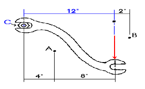
The moment arm for calculating the moment around point C is 12 inches. The magnitude of the moment about point C is 12 inches multiplied by the force of 100 lbs to give a total moment of 1200 inch-lbs (or 100 ft-lbs).
Moment Arm (d) = 12 inches
Magnitude (F) = 100 lbs
Moment = M = 100 lbs x 12 in. = 1200 in-lbs
Similarly, we can find the moments about any point in space.
Moment @ | A | B | D |
Moment Arm | 8 inches | 2 inches | 0 inches |
Magnitude of F | 100 pounds | 100 pounds | 100 pounds |
Total Moment | 800 in- pounds | 200 in- pounds | 0 in- pounds |
|
 |
 |
 |
A moment causes a rotation about a point or axis. If the moment is to be taken about a point due to a force F, then in order for a moment to develop, the line of action cannot pass through that point. If the line of action does go through that point, the moment is zero because the magnitude of the moment arm is zero. Such was the case for point D in the previous wrench problem. The total moment was zero because the moment arm was zero as well.
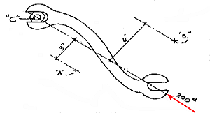
As another example, let us assume that 200 pound force is applied to the wrench as indicated. The moment of the 200 pound force applied at C is zero because:
M = F x d = 200 lbs x 0 in = 0 in-lbs
In other words, there is no tendency for the 200 pound force to cause the wrench to rotate the nut. One could increase the magnitude of the force until the bolt finally broke off (shear failure).
The moment about points X, Y, and Z would also be zero because they also lie on the line of action.