UNIT 7
BENDING MOMENT
Transverse loading is a load applied vertically to the plane of the longitudinal axis of a configuration, such as a wind load. It causes the material to bend and rebound from its original position, with inner tensile and compressive straining associated with the change in curvature of the material.
Transverse loading is also known as transverse force or crosswise force.
Transverse loading encourages shear forces that cause shear deformation of a material and increase its slanting deflection. When a transverse load is applied on a beam, it deforms and tensions develop within it. Therefore, bending moments are created by transverse loads once applied to beams.
Transverse loading occurs in traditional and cutting off stresses in transverse segments. Longitudinal cutting off strains may occur in any material subjected to crosswise loading. It additionally causes bending and shears in beams. Transverse loading of a beam could comprise concentrated loads and distributed loads or a mix of each, producing internal forces corresponding to a shear force and both.
Transverse Loading: Calculation of Bending Moment and Shear Force in Beams
Skeletal members that primarily carry loading applied perpendicular to their axes(transversely or laterally) will be referred to as beams. As they carry transverse loading they undergo bending or flexural deformations and to some extent shearing If the cross-sectional dimensions of a beam are small compared to their span (length of the beam undergoing bending) it may be classified as slender beam.
In most practical situations, the beams may be treated as slender. Slender beams undergo flexural deformations where one side of the beam gets stretched while the other side gets shortened as shown in Figure

There will also be shearing type deformation, which is considerable in beams that are short(cross-sectional dimensions being comparable to the span).
The deformations shown in the diagrams above are grossly exaggerated, and in practice the displacements are very small .Beams are used in most structures and machines, and the effect of transverse loading on beams is often the main criteria in structural design. Typical examples include bridges, roof structural elements (purlins, rafters), floor-beams, machine elements such as levers, cranks, manipulator arms etc. Even members that predominantly carry torsional loading such as transmission shafts are susceptible to flexural deformations, and knowledge of their flexural behaviour is needed in calculating the whirling speeds (the speed at which the shaft has a tendency to whirl) of shafts. Therefore, it is important to be able to calculate the internal actions in beams due to transverse loading.
Deformation of a beam under transverse loading
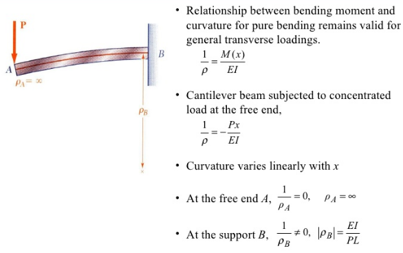
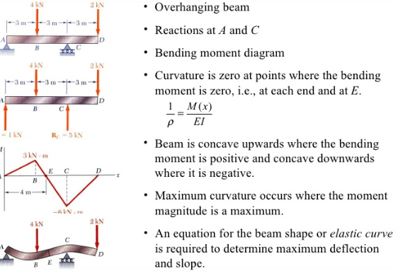
Shear force refers to the force acting along on a surface. Basically, the force forms no inclination/angle to the surface on which it is acting on. Within a beam, the shear force at any section is basically the algebraic sum of the lateral forces acting on either side of the section. For example, take a look at this beam:

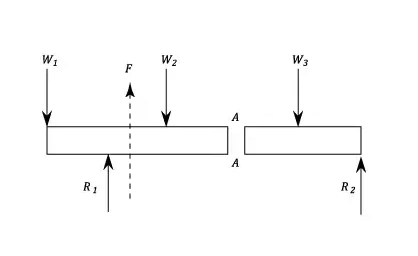
Consider a beam carrying loads W1, W2 and W3 with R1 and R2 as the support reactions. If we cut the beam at section AA, then since the resultant forces at the left of section AA is F upwards, then the shearing force at section AA is F downwards.
On the other hand, the bending moment refers to the internal rotational moments that cause a section to bend. In the case of a beam, it can be calculated as the algebraic sum of the moments about the section of all forces acting on either side of the section, where a sagging moment will make the beam concave (positive) upwards at that section, and vice versa for a hogging moment (i.e. negative).
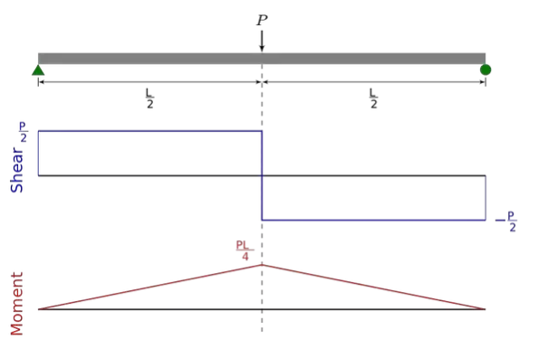
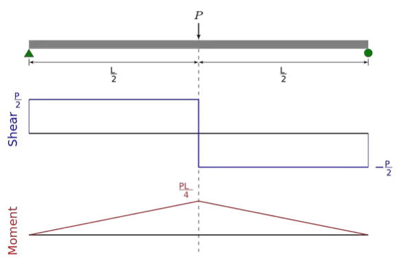
This diagram basically is an example of the shear force and bending moment of a simply supported beam subjected to a point load on the centre:
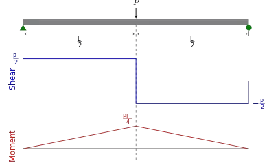

It is important to calculate both the shear force and bending moment because it is extremely handy when it comes to structural design. By determining the values of the shear force and bending moment across a structure/structural member, we can accordingly decide the appropriate material or size that can help it to withstand these internal forces and moments. This is crucial because using the wrong material or size can ultimately cost the structure/structural elements its integrity for failing to support the designed loads.
Shear and bending moment diagrams are analytical tools used in conjunction with structural analysis to help perform structural design by determining the value of shear force and bending moment at a given point of a structural element such as a beam. These diagrams can be used to easily determine the type, size, and material of a member in a structure so that a given set of loadscan be supported without structural failure. Another application of shear and moment diagrams is that the deflection of a beam can be easily determined using either the moment area method or the conjugate beam method.
Shear Forces and Bending Moments in Beams
Bending Stress:
σ = My/I
Moment of Inertia: Ix = ∫Ay2 dA
Iy = ∫Ax2 dA
Parallel Axis Theorem: Ix = Ixc + Ad2
Iy = Iyc + Ad2
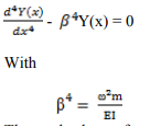
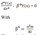
For a cantilever beam exposed to free vibration, and the system is considered as continuous system considering the beam mass as distributed along with the stiffness of the shaft, the equation of motion can be written as given by the following equations,

Where, E is the modulus of rigidity of beam material, I is the moment of inertia of the cross section of the beam, Y(x) is displacement in y direction at distance x from fixed end, ω is the circular natural frequency, m is the mass per unit length, m = ρA(x), ρ is the density of the material, x is the distance measured from the fixed end. Fig.17 shows a cantilever beam having rectangular cross section, which is subjected to bending vibration by giving a small initial displacement at the free end; and Fig. 18 depicts a cantilever beam under the free vibration. The boundary conditions for a cantilever beam (Fig.) are given by;

For uniform beam under free vibration from equation we get
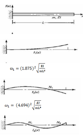
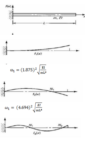
The mode shapes for a continious cantilever beam is given by

Where, N= 1,2,3,…..∞ and 
Where, α = 1.875, 4.694, 7.885

From Strength of Materials, the deflection, x, at the tip of a cantilever beam is given by

Where x tip displacement
P applied load (also referred to as F)
L length of the cantilever beam
E Young’s Modulus of Elasticity
I bending moment of inertia
The deflection at the end of the cantilever beam can be expressed as F = k x (4) and therefore, the stiffness of the cantilever beam can be expressed as F = k x
And therefore, the stiffness of the cantilever beam can be expressed as K= 3EI/L3
Realizing that the natural frequency is
 (in rad/sec)
And natural frequency of first mode of cantilever beam of the continuous solution is
 (where w = weight g =gravitational constant) allows the effective mass at the tip of the cantilever beam to be determined. This approximation allows the cantilever beam to be modeled as a single degree of freedom system since the mass and stiffness are known.
CANTILEVER BEAM:
Material used for Cantilever Beam:
A) Mild Steel
1) Density 7850 kg/m^3
2) Young’s modulus 210×10^9 Pa
3) Poisson’s Ratio 0.303
B) Aluminium
1) Density 2700kg/m^3
2) Young’s modulus 69×10^9 Pa
3) Poisson’s Ratio 0.334
C) Composite material (Glass fiber)
1) Density 2530 kg/m^3
2) Young’s modulus 72×10^9 Pa
3) Poisson’s Ratio 0.22
D) Geometries of cantilever beam:
1) Length 600mm
2) Width 50mm
3) Height 5mm
Also each beam is having 5 geometries viz. No hole, One hole, Two hole, Three hole, Four hole. These hole are equally spaced.
COMPOSITE: GLASS FIBER Material used:
1. Glass Fiber (E- Glass fiber)
2. Transparent Plastic sheet
3. Resin: Epoxy resin
4. Colour: Polyester epoxy pigment
5. Hardener: Epoxy hardener
ANALYSIS OF CANTILEVER BEAM USING ANSYS:
Problem definition: We have a MS cantilever beam with no hole in it with dimensions as:
1) Length 600mm
2) Width 50mm
3) Height 5mm
Given MS has following properties:
1) Density 7850 kg/m^3
2) Young’s modulus 210×10^9 Pa
3) Poisson’s Ratio 0.303
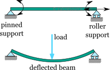
The simply supported beam is one of the simplest structures. It features only two supports, one at each end. One is a pinned support and the other is a roller support. With this configuration, the beam is inhibited from any vertical movement at both ends whereas it is allowed to rotate freely. Due to the roller support it is also allowed to expand or contract axially, though free horizontal movement is prevented by the other support.
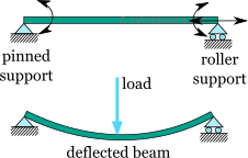
Removing any of the supports inserting an internal hinge, would render the simply supported beam to a mechanism, that is body the moves without restriction in one or more directions. Obviously this is unwanted for a load carrying structure. Therefore, the simply supported beam offers no redundancy in terms of supports, and if a local failure occurs the whole structure would collapse. These type of structures that offer no redundancy are called critical or determinant structures. To the contrary, a structure that features more supports than required to restrict its free movements is called redundant or indeterminate structure.
Is only part of the static analysis of a structure. Most of the time, it is very important to determine the forces and the moments that occur inside the beam, as a result of the imposed loading. Typically, for a plane structure that is loaded in its plane, the following internal actions may occur:
- Axial force,
- Transverse shear force,
- Bending moment,
To find these internal actions, at any particular point of the structure, a section cut must be performed. In simple words the structure is cut into two parts, at the specific point of interest. Then, by enforcing equilibrium equations on either of the two parts, the internal actions can be determined. The procedure can be summarized in the following steps:
- Cut the structure in the desired point, where the internal actions are going to be found. Select one of the two parts to work with
- Assign the internal actions to variables (i.e. for axial force, for shear force and for bending moment\) and place them to the structure, at the point of the cut, with their positive directions (more on this later)
- Write the equilibrium equations, taking into account the internal actions and any imposed loads and support reactions occurring in the selected part.
- Solve the system of equations
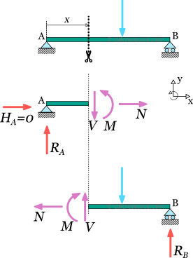
In the following figure, a section cut is illustrated at a random point of a simply supported beam. Let's select the left part to work with. The unknown internal actions, , and have been inserted at the cut, with their positive directions. For the moment, accept the shown directions as correct ones. We will elaborate on the convention for positive directions later.
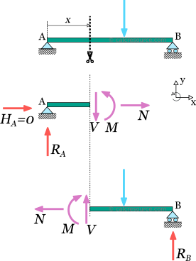
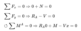
Next we have to write the equilibrium equations for the left part. Apart from the internal actions N, V, M, and , there are support reactions RA, HA and at point A. There is no imposed load though, in the left part. The equilibrium equations, according to our axes system (see figure), are the following:
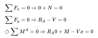
From the first equation we get N = 0, which means that no axial force occurs at the specific point. But since this point is a random one, it can be claimed that there is no axial force along the beam span. It is not hard to prove, that unless there is a horizontal component of imposed loads, the axial force in a simply supported beam is always zero.
Unless there is a horizontal component of imposed loads, the axial force in a simply supported beam is always zero
From the second equation we get: V=RA.
And substituting to the third equation, we get: .M=RAx
Normally, there is no need to examine both parts, after making a section cut
Point forces and point moments
Finding the shear force and the bending moment at the points where a concentrated force or bending moment is imposed requires some more consideration. Specifically, at the location of a point load, the resulting shear force is different, to the left and the right of the application point.
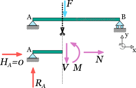
To illustrate this, let's consider the following simply supported beam. We have to determine the shear force, at the point where the imposed load is applied. So, a section cut is performed, just to the left of the application point. We also select the left part. The equilibrium of forces on axis y becomes:

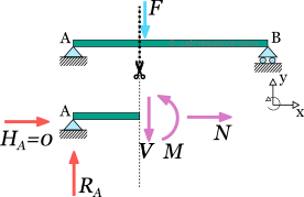
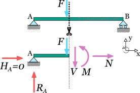
We have not included the force F in the equilibrium because the cut was made to the left of the application point, thus, leaving F to the right part of the cut. Now let's make the cut a little bit to the right of the force F. We select again, the left part, but this time the force is included. The equilibrium becomes:

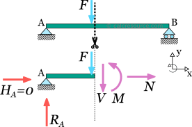
It is clear that:  . It is therefore important in such cases, to clarify the side of the application point we evaluate the transverse shear force, left or right.
Similar considerations apply when a point moment is present. To the left and right of its application point, the resulting bending moment is different.
Sign convention for bending moments and shear forces
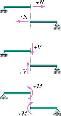
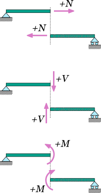
Regarding the sign convention for the internal forces and moments, at any section cut, the following conventions are usually adopted:
- The axial force is considered positive when it causes tension to the part
- The shear force is positive when it causes a clock-wise rotation of the part.
- The bending moment is positive when it causes tension to the lower fiber of the beam and compression to the top fiber.
These rules, though not mandatory, are rather established. A different set of rules, if followed consistently would also produce correct results.
Simple Beam
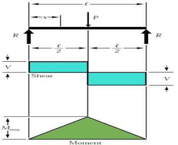
The simple beam above has two supports and a center load.
The simple beam has two supports at each end. These supports or reactions (R) are not fixed; hence they are free to move. This affects how the loads will react with supports in terms of shear and it’s bending moment. If they were fixed, the shear and moment forces would react differently (explained later). The first case is concentrated load (P), which acts on the beam at its center. The value of the force at each reaction is equates to the load at the center:
R = P/2
Where P is the value of the load force.
For the case of the concentrated load at the center, the shear stress (V) has the same value as the reaction force (R=V). One creates the shear diagram by analysing the forces acting on the beam from one side to the other. If we start on the left, the reaction forces push up on the beam. This translates into the shear diagram as rising to the same value and going across with no slope until it reaches the center load. The shear value then is directed down the same value as the center load and continues across with no slope until it reaches second reaction load on the other end of the beam.
The moment is determined in a similar fashion. The slope of the moment diagram over the interval 0 is equal to the value of shear. The change in moment is equal to the area under shear diagram. In this case, the maximum moment is derived by the following equation
Mmax = (P.l)/4
Where l is the length of the beam.
If the load was not centrally located, the value of R would be determined by its location. Let’s assume that the load P is not in the center, but a distance value a from the left and a distance value b from the right. The reaction values would be determined by:
R1=V1= (P. b)/l
R2=V2= (P. a)/l
Using the equations above for the reaction loads, you could alter the previous formulas as required.
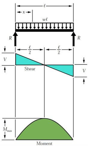
This simple beam is experiencing experiencing a uniformed load across the span of the beam.
A different loading case is a uniformed load. The load is equally distributed across the length of the beam. The distributed load is quantified as load per distance (i.e., 10 kN-m) and can also be equated as a concentrated load at a specific point along the bar. The magnitude of the force is equal to the area under the curve of the distributed load, and the location is at the center of mass of the distributed load. For this case, the force at the reactions, which is also the maximum shear force, is expressed by:
R = V = (w.l)/2
Where w is equal to the distributed load.
Here the shear diagram and the moment diagram change slightly. In the first case, the shear diagram is straight across until it encounters the load and shifts to the opposite direction. The shear in the second case is continuous negative slope. To find the shear force at any point, use the equation:
Vx=w (l/2 – x)
The maximum moment can be determined by:
Mmax = (w. l2)/8
Overhanging Beam
If the end portion of a beam extends beyond the support, then the beam is known as overhanging beam. Overhanging may be on one of the supports or on both the sides.
In the case of an overhanging beam, the bending moment is positive between the supports, whereas the bending moment is negative for the overhanging portion.
At the same point on the beam, the bending moment is zero or changes sign from positive to negative value or vice versa. This point where the bending moment changes sign is called as the point of contra flexure or point of inflexion.
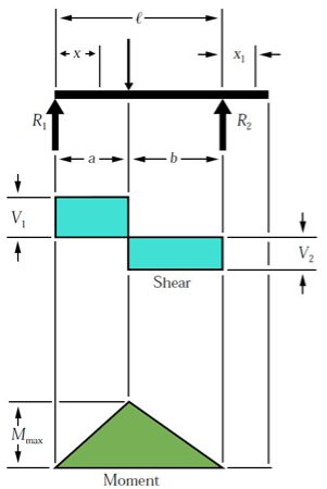
The overhanging beam, unlike the simple or fixed beam, has one end that is unsupported.
The overhanging beam has the first support at the beam’s end while the second support is located along the beam toward the center. In this particular example, the portion of the beam that passes the second support does not experience shear or bending. The visual depiction of shear and bending is similar to the simple beam. However, since the example above does not have a center load, the shear calculations will be different for each support:
R1= V1 = P.b/l
(max shear value when a < b)
R2 = V2 = P.a/l
(Maximum shear value when a > b)
Maximum moment is calculated by the following equation:
Mmax = P.ab/l
Double Overhanging Beam
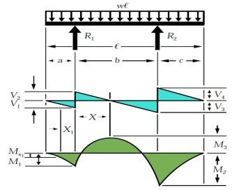
Both ends in the image above are unsupported. The double overhanging beam instead has supports located towards the center of the beam.
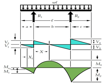
The double overhanging beam is the same concept as the single, except with both supports located along and within the beams length. In this case, the load across the beam is a uniformed load and impacts the shear and bending diagrams in a more complicated way. From left to right, the first shear value is determined by the distance of the first support to the end multiplied by the uniformed load.
V1=wa
The reaction load at the first support is determined by:
R1 = w l (l-2c)/2b
Where b and c are distances between supports and the remaining edge distance, respectively.
The shear value then changes at the first support location and is determined by the difference between the first shear value and the first support load:
V2=R1 – V1
Continuing left to right, the reaction load at the second support is:
R2 = w l (1-2a)/2b
Now the third shear value can be calculated as:
V3=R2-V4
Where V4 is the shear caused by the uniformed load at the right side overhanging edge:
V4=w.c
The momentum profile is much different in this case. As a result of the support locations, three different momentums take place. Using the same principle as we did for shear, we can analyze the moment values from left to right. The first bending moment is calculated simply by:
M1=-wa2/2
The next moment, which is M3 in the example above, is calculated with the following equation:
M3 = R1 (R1/2w – a)
The final moment, M2, is determined by:
M2=-wc2 / 2
These are the three moments acting on the beam for this case. Maximum moment is determined by:
Mmax = R1x- w (a + x ) 2 /2
Where x = R1/w – a
Relationship between Load, Shear, and Moment
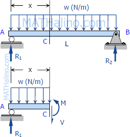
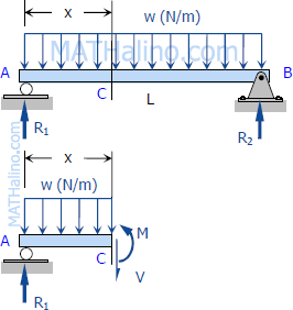
The vertical shear at C in the figure is taken as
VC= (ΣFv) L=R1−wx
Where R1 = R2 = w.L/2
Vc =wL2−wxVc=wL2−wx
The moment at C is
MC= (ΣMC) =wLx/2−wx(x/2)
MC=wLx/2−wx2 /2
If we differentiate M with respect to x:
dM/dx=wL/2⋅dx/dx−w/2(2x⋅dx/dx)
DM/dx=wL/2−wx=shear
Thus,
DM/dx=V
Thus, the rate of change of the bending moment with respect to x is equal to the shearing force, or the slope of the moment diagram at the given point is the shear at that point
Differentiate V with respect to x gives
dV/dx=0−w
thus,
DV/ dx=Load
Thus, the rate of change of the shearing force with respect to x is equal to the load or the slope of the shear diagram at a given point equal at the point
Properties of Shear and Moment Diagrams
The following are some important properties of shear and moment diagrams:
- The area of the shear diagram to the left or to the right of the section is equal to the moment at that section.
- The slope of the moment diagram at a given point is the shear at that point.
- The slope of the shear diagram at a given point equals the load at that point.
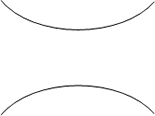 The maximum moment occurs at the point of zero shears. This is in reference to property number 2, that when the shear (also the slope of the moment diagram) is zero, the tangent drawn to the moment diagram is horizontal.
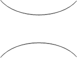
- When the shear diagram is increasing, the moment diagram is concave upward.
- When the shear diagram is decreasing, the moment diagram is concave downward.
Sign Convention
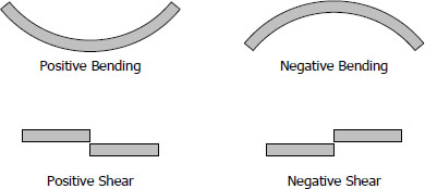
The customary sign conventions for shearing force and bending moment are represented by the figures below. A force that tends to bend the beam downward is said to produce a positive bending moment. A force that tends to shear the left portion of the beam upward with respect to the right portion is said to produce a positive shearing force.
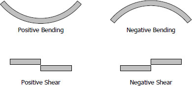
An easier way of determining the sign of the bending moment at any section is that upward forces always cause positive bending moments regardless of whether they act to the left or to the right of the exploratory section.
A shearing force occurs when a perpendicular force is applied to static material (in this case a beam). Think of a knife cutting through a carrot. Imagine the beam is the carrot and a point load is the knife. As the knife applies a downward force, it cuts (or shears) the carrot. These forces occur along numerous points of a beam, and it is important to determine where these shears are at the greatest points as this may be where a beam fails.
To calculate the shear forces of a beam, follow the following simple steps:
1. Start with the far left side of the beam
If there is an upward force (i.e a support) then the SFD will start at this force above the x-axis. If there is a downward point load and no support, than the shear force diagram will start as a negative at the value of the point load.
Move across the beam
As you come across loads, you simply add (or subtract) these loads from the value you already have, keeping a cumulative total.
It is much easier to understand when considering an example of a how to calculate a Shear Force Diagram. So let's consider the following example to calculate the shear force diagram of a beam:

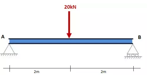

Step 1: After calculating the reactions at A and B, start the Shear Force Diagram at the first value of the force acting on the beam. In this case it is a +10kN due to the reaction at point A:

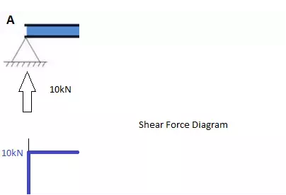
Step 2: Keep moving across the beam, stopping at every load that acts on the beam. When you get to a load, add to the Shear Force Diagram by the amount of the force. In this case we have come to a negative 20kN force, so we will minus 20kN from the existing 10kN. i.e. 10kN - 20kN = -10kN.
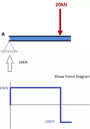
Moving across the beam again, we come to another force; a positive 10kN reaction at support B. Again, add this +10kN to the shear force diagram (which is currently at -10kN) which will bring us to a shear force of 0. Since we are at the end of the beam, we will go no further and we have our final Shear Force Diagram (SFD):
Things to keep in mind:
- The area under the SFD above the x axis should equal the area between the x-axis and the SFD below the x axis. i.e the area should sum to zero. Check this is true in our above example.
- Any points where the SFD cross the x-axis, will be a max or min Bending Moment
- The SFD should always equal zero at both ends.
How to Calculate the Bending Moment Diagram of a Beam
Below are simple instructions on how to calculate the bending moment diagram of a simple supported beam. Study this method as it is very versatile (and can be adapted to many different types of problem. The ability to calculate the bending moment of a beam is very common practice for structural engineers and often comes up in college and high school exams.
Firstly, what is a Bending Moment? A moment is rotational force that occurs when a force is applied perpendicularly to a point at a given distance away from that point. It is calculated as the perpendicular force multiplied by the distance from the point. A Bending Moment is simply the bend that occurs in a beam due to a moment. It is important to remember two things when calculating bending moments; (1) the standard units are Nm and (2) clockwise bending is taken as negative. Anyways, with the boring definitions out of the way, let's look at the steps to calculate a bending moment diagram:
1. Calculate reactions at supports and draw Free Body Diagram (FBD).
If you're not sure how to do this, click here for our tutorial. Once you have the reactions, draw your Free Body Diagram and Shear Force Diagram underneath the beam:
2. From left to right, make "cuts" before and after each reaction/load
TO calculate the bending moment of a beam, we must work in the same way we did for the Shear Force Diagram. Starting at x = 0 we will move across the beam and calculate the bending moment at each point
Cut 1
Make a "cut" just after the first reaction of the beam. In our simple example:
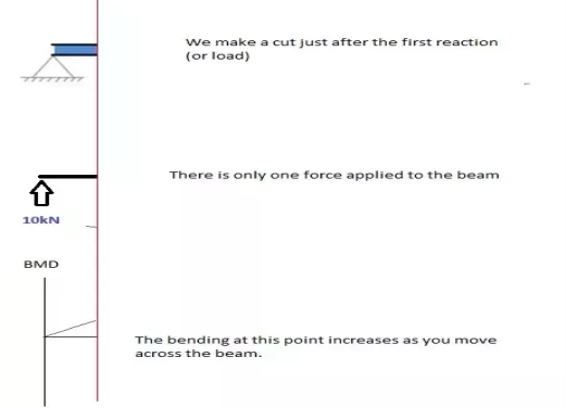
So, when we cut the beam, we only cosider the forces that are applied to the left of our cut. In this case we have a 10kN force in the upward direction. Now as you recall, a bending moment is simply the force x distance. So as we move further from the force, the magnitude of the bending moment will increase. We can see this in our BMD. The equation for this part of our bending moment diagram is:
-M(x) = 10(-x)
M(x) = 10x
Cut 2
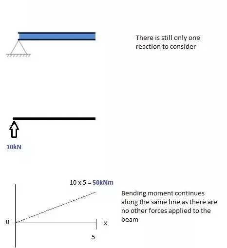

This cut is made just before the second force along the beam. Since there are no other loads applied between the first and second cut, the bending moment equation will remain the same. This means we can calculate the maximum bending moment (in this case at the midpoint, or x = 5) by simply substituting x=5 into the above equation:

Cut 3
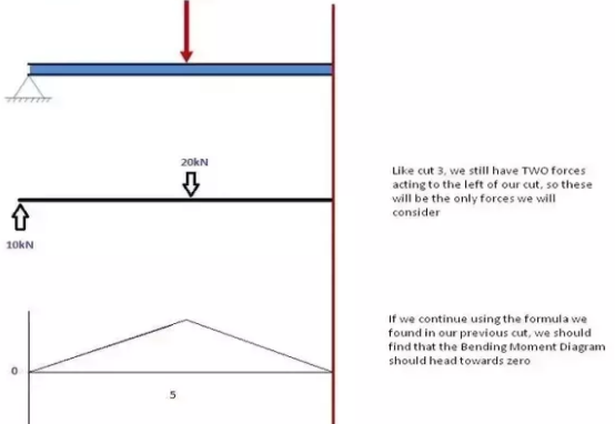
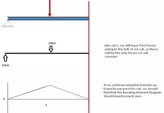
This cut is made just after the second force along the beam. Now we have TWO forces that act to the left of our cut: a 10kN support reaction and a -20kN downward acting load. So now we must consider both these forces as we progress along our beam. For every metre we move across the beam, there will a +10kNm moment added from the first force and -20kNm from the second. So after the point x=5, our Bending Moment Equation becomes:
M(x) = 50 +10(x-5) - 20(x-5)
M(x) = 50 -10(x-5) for 5 ≤ x ≤ 10
NOTE: The reason we write (x-5) is because we want to know the distance from the pt x=5 only. Anything before this point uses a previous equation.
Cut 4
Again, let's move across to the right of our beam and make a cut just before our next force. In this case, our next cut will occur just before the reaction from Right Support. Since there are no other forces between the support and our previous cut, the equation will remain the same:
M(x) = 50 -10(x-5) for 5 ≤ x≤ 10
And let's substitute x=10 into this to find the find bending moment at the end of the beam:
M(x) = 50 - 10(10-5) = 0kNm
Variation of Shear force and bending moments:
Variation of Shear force and bending moments for various standard loads are as shown in the following Table
Type of load
SFD/BMD | Between point loads OR for no load region | Uniformly distributed load | Uniformly varying load |
Shear Force Diagram | Horizontal line | Inclined line | Two-degree curve (Parabola) |
Bending Moment Diagram | Inclined line | Two-degree curve (Parabola) | Three-degree curve (Cubic-parabola) |
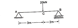
Question - Find the support reactions of given beam for loading as shown below.
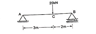
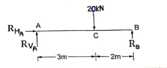
 Draw FBD of given beam & applying conditions of equilibrium
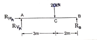
∑fx = 0
RHA = 0
∑fxy = 0
RVA – 20 + RB = 0
RVA + RB = 20 ------(1)
Taking moments at A
∑MA = 0
(20 × 3) – (RB × 5) = 0
60 – 5RB

RB = 12 kN  put in equation (1)
 RVA + 12 = 20
 RVA = 20-12 = RVA = 8 kN
UNIT 7
BENDING MOMENT
Transverse loading is a load applied vertically to the plane of the longitudinal axis of a configuration, such as a wind load. It causes the material to bend and rebound from its original position, with inner tensile and compressive straining associated with the change in curvature of the material.
Transverse loading is also known as transverse force or crosswise force.
Transverse loading encourages shear forces that cause shear deformation of a material and increase its slanting deflection. When a transverse load is applied on a beam, it deforms and tensions develop within it. Therefore, bending moments are created by transverse loads once applied to beams.
Transverse loading occurs in traditional and cutting off stresses in transverse segments. Longitudinal cutting off strains may occur in any material subjected to crosswise loading. It additionally causes bending and shears in beams. Transverse loading of a beam could comprise concentrated loads and distributed loads or a mix of each, producing internal forces corresponding to a shear force and both.
Transverse Loading: Calculation of Bending Moment and Shear Force in Beams
Skeletal members that primarily carry loading applied perpendicular to their axes(transversely or laterally) will be referred to as beams. As they carry transverse loading they undergo bending or flexural deformations and to some extent shearing If the cross-sectional dimensions of a beam are small compared to their span (length of the beam undergoing bending) it may be classified as slender beam.
In most practical situations, the beams may be treated as slender. Slender beams undergo flexural deformations where one side of the beam gets stretched while the other side gets shortened as shown in Figure

There will also be shearing type deformation, which is considerable in beams that are short(cross-sectional dimensions being comparable to the span).
The deformations shown in the diagrams above are grossly exaggerated, and in practice the displacements are very small .Beams are used in most structures and machines, and the effect of transverse loading on beams is often the main criteria in structural design. Typical examples include bridges, roof structural elements (purlins, rafters), floor-beams, machine elements such as levers, cranks, manipulator arms etc. Even members that predominantly carry torsional loading such as transmission shafts are susceptible to flexural deformations, and knowledge of their flexural behaviour is needed in calculating the whirling speeds (the speed at which the shaft has a tendency to whirl) of shafts. Therefore, it is important to be able to calculate the internal actions in beams due to transverse loading.
Deformation of a beam under transverse loading
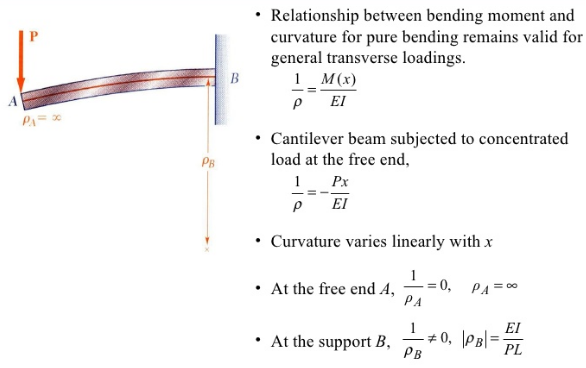
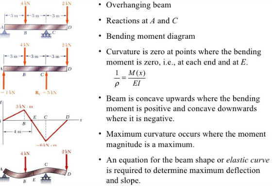
Shear force refers to the force acting along on a surface. Basically, the force forms no inclination/angle to the surface on which it is acting on. Within a beam, the shear force at any section is basically the algebraic sum of the lateral forces acting on either side of the section. For example, take a look at this beam:

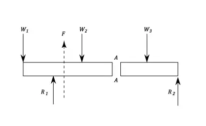
Consider a beam carrying loads W1, W2 and W3 with R1 and R2 as the support reactions. If we cut the beam at section AA, then since the resultant forces at the left of section AA is F upwards, then the shearing force at section AA is F downwards.
On the other hand, the bending moment refers to the internal rotational moments that cause a section to bend. In the case of a beam, it can be calculated as the algebraic sum of the moments about the section of all forces acting on either side of the section, where a sagging moment will make the beam concave (positive) upwards at that section, and vice versa for a hogging moment (i.e. negative).
This diagram basically is an example of the shear force and bending moment of a simply supported beam subjected to a point load on the centre:
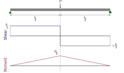

It is important to calculate both the shear force and bending moment because it is extremely handy when it comes to structural design. By determining the values of the shear force and bending moment across a structure/structural member, we can accordingly decide the appropriate material or size that can help it to withstand these internal forces and moments. This is crucial because using the wrong material or size can ultimately cost the structure/structural elements its integrity for failing to support the designed loads.
Shear and bending moment diagrams are analytical tools used in conjunction with structural analysis to help perform structural design by determining the value of shear force and bending moment at a given point of a structural element such as a beam. These diagrams can be used to easily determine the type, size, and material of a member in a structure so that a given set of loadscan be supported without structural failure. Another application of shear and moment diagrams is that the deflection of a beam can be easily determined using either the moment area method or the conjugate beam method.
Shear Forces and Bending Moments in Beams
Bending Stress:
σ = My/I
Moment of Inertia: Ix = ∫Ay2 dA
Iy = ∫Ax2 dA
Parallel Axis Theorem: Ix = Ixc + Ad2
Iy = Iyc + Ad2
For a cantilever beam exposed to free vibration, and the system is considered as continuous system considering the beam mass as distributed along with the stiffness of the shaft, the equation of motion can be written as given by the following equations,

Where, E is the modulus of rigidity of beam material, I is the moment of inertia of the cross section of the beam, Y(x) is displacement in y direction at distance x from fixed end, ω is the circular natural frequency, m is the mass per unit length, m = ρA(x), ρ is the density of the material, x is the distance measured from the fixed end. Fig.17 shows a cantilever beam having rectangular cross section, which is subjected to bending vibration by giving a small initial displacement at the free end; and Fig. 18 depicts a cantilever beam under the free vibration. The boundary conditions for a cantilever beam (Fig.) are given by;

For uniform beam under free vibration from equation we get
The mode shapes for a continious cantilever beam is given by

Where, N= 1,2,3,…..∞ and 
Where, α = 1.875, 4.694, 7.885

From Strength of Materials, the deflection, x, at the tip of a cantilever beam is given by

Where x tip displacement
P applied load (also referred to as F)
L length of the cantilever beam
E Young’s Modulus of Elasticity
I bending moment of inertia
The deflection at the end of the cantilever beam can be expressed as F = k x (4) and therefore, the stiffness of the cantilever beam can be expressed as F = k x
And therefore, the stiffness of the cantilever beam can be expressed as K= 3EI/L3
Realizing that the natural frequency is
 (in rad/sec)
And natural frequency of first mode of cantilever beam of the continuous solution is
 (where w = weight g =gravitational constant) allows the effective mass at the tip of the cantilever beam to be determined. This approximation allows the cantilever beam to be modeled as a single degree of freedom system since the mass and stiffness are known.
CANTILEVER BEAM:
Material used for Cantilever Beam:
A) Mild Steel
1) Density 7850 kg/m^3
2) Young’s modulus 210×10^9 Pa
3) Poisson’s Ratio 0.303
B) Aluminium
1) Density 2700kg/m^3
2) Young’s modulus 69×10^9 Pa
3) Poisson’s Ratio 0.334
C) Composite material (Glass fiber)
1) Density 2530 kg/m^3
2) Young’s modulus 72×10^9 Pa
3) Poisson’s Ratio 0.22
D) Geometries of cantilever beam:
1) Length 600mm
2) Width 50mm
3) Height 5mm
Also each beam is having 5 geometries viz. No hole, One hole, Two hole, Three hole, Four hole. These hole are equally spaced.
COMPOSITE: GLASS FIBER Material used:
1. Glass Fiber (E- Glass fiber)
2. Transparent Plastic sheet
3. Resin: Epoxy resin
4. Colour: Polyester epoxy pigment
5. Hardener: Epoxy hardener
ANALYSIS OF CANTILEVER BEAM USING ANSYS:
Problem definition: We have a MS cantilever beam with no hole in it with dimensions as:
1) Length 600mm
2) Width 50mm
3) Height 5mm
Given MS has following properties:
1) Density 7850 kg/m^3
2) Young’s modulus 210×10^9 Pa
3) Poisson’s Ratio 0.303
The simply supported beam is one of the simplest structures. It features only two supports, one at each end. One is a pinned support and the other is a roller support. With this configuration, the beam is inhibited from any vertical movement at both ends whereas it is allowed to rotate freely. Due to the roller support it is also allowed to expand or contract axially, though free horizontal movement is prevented by the other support.
Removing any of the supports inserting an internal hinge, would render the simply supported beam to a mechanism, that is body the moves without restriction in one or more directions. Obviously this is unwanted for a load carrying structure. Therefore, the simply supported beam offers no redundancy in terms of supports, and if a local failure occurs the whole structure would collapse. These type of structures that offer no redundancy are called critical or determinant structures. To the contrary, a structure that features more supports than required to restrict its free movements is called redundant or indeterminate structure.
Is only part of the static analysis of a structure. Most of the time, it is very important to determine the forces and the moments that occur inside the beam, as a result of the imposed loading. Typically, for a plane structure that is loaded in its plane, the following internal actions may occur:
- Axial force,
- Transverse shear force,
- Bending moment,
To find these internal actions, at any particular point of the structure, a section cut must be performed. In simple words the structure is cut into two parts, at the specific point of interest. Then, by enforcing equilibrium equations on either of the two parts, the internal actions can be determined. The procedure can be summarized in the following steps:
- Cut the structure in the desired point, where the internal actions are going to be found. Select one of the two parts to work with
- Assign the internal actions to variables (i.e. for axial force, for shear force and for bending moment\) and place them to the structure, at the point of the cut, with their positive directions (more on this later)
- Write the equilibrium equations, taking into account the internal actions and any imposed loads and support reactions occurring in the selected part.
- Solve the system of equations
In the following figure, a section cut is illustrated at a random point of a simply supported beam. Let's select the left part to work with. The unknown internal actions, , and have been inserted at the cut, with their positive directions. For the moment, accept the shown directions as correct ones. We will elaborate on the convention for positive directions later.
Next we have to write the equilibrium equations for the left part. Apart from the internal actions N, V, M, and , there are support reactions RA, HA and at point A. There is no imposed load though, in the left part. The equilibrium equations, according to our axes system (see figure), are the following:
From the first equation we get N = 0, which means that no axial force occurs at the specific point. But since this point is a random one, it can be claimed that there is no axial force along the beam span. It is not hard to prove, that unless there is a horizontal component of imposed loads, the axial force in a simply supported beam is always zero.
Unless there is a horizontal component of imposed loads, the axial force in a simply supported beam is always zero
From the second equation we get: V=RA.
And substituting to the third equation, we get: .M=RAx
Normally, there is no need to examine both parts, after making a section cut
Point forces and point moments
Finding the shear force and the bending moment at the points where a concentrated force or bending moment is imposed requires some more consideration. Specifically, at the location of a point load, the resulting shear force is different, to the left and the right of the application point.
To illustrate this, let's consider the following simply supported beam. We have to determine the shear force, at the point where the imposed load is applied. So, a section cut is performed, just to the left of the application point. We also select the left part. The equilibrium of forces on axis y becomes:

We have not included the force F in the equilibrium because the cut was made to the left of the application point, thus, leaving F to the right part of the cut. Now let's make the cut a little bit to the right of the force F. We select again, the left part, but this time the force is included. The equilibrium becomes:

It is clear that:  . It is therefore important in such cases, to clarify the side of the application point we evaluate the transverse shear force, left or right.
Similar considerations apply when a point moment is present. To the left and right of its application point, the resulting bending moment is different.
Sign convention for bending moments and shear forces
Regarding the sign convention for the internal forces and moments, at any section cut, the following conventions are usually adopted:
- The axial force is considered positive when it causes tension to the part
- The shear force is positive when it causes a clock-wise rotation of the part.
- The bending moment is positive when it causes tension to the lower fiber of the beam and compression to the top fiber.
These rules, though not mandatory, are rather established. A different set of rules, if followed consistently would also produce correct results.
Simple Beam
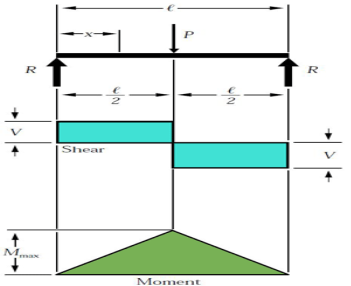
The simple beam above has two supports and a center load.
The simple beam has two supports at each end. These supports or reactions (R) are not fixed; hence they are free to move. This affects how the loads will react with supports in terms of shear and it’s bending moment. If they were fixed, the shear and moment forces would react differently (explained later). The first case is concentrated load (P), which acts on the beam at its center. The value of the force at each reaction is equates to the load at the center:
R = P/2
Where P is the value of the load force.
For the case of the concentrated load at the center, the shear stress (V) has the same value as the reaction force (R=V). One creates the shear diagram by analysing the forces acting on the beam from one side to the other. If we start on the left, the reaction forces push up on the beam. This translates into the shear diagram as rising to the same value and going across with no slope until it reaches the center load. The shear value then is directed down the same value as the center load and continues across with no slope until it reaches second reaction load on the other end of the beam.
The moment is determined in a similar fashion. The slope of the moment diagram over the interval 0 is equal to the value of shear. The change in moment is equal to the area under shear diagram. In this case, the maximum moment is derived by the following equation
Mmax = (P.l)/4
Where l is the length of the beam.
If the load was not centrally located, the value of R would be determined by its location. Let’s assume that the load P is not in the center, but a distance value a from the left and a distance value b from the right. The reaction values would be determined by:
R1=V1= (P. b)/l
R2=V2= (P. a)/l
Using the equations above for the reaction loads, you could alter the previous formulas as required.
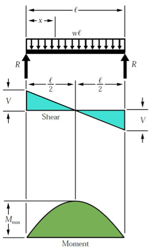
This simple beam is experiencing experiencing a uniformed load across the span of the beam.
A different loading case is a uniformed load. The load is equally distributed across the length of the beam. The distributed load is quantified as load per distance (i.e., 10 kN-m) and can also be equated as a concentrated load at a specific point along the bar. The magnitude of the force is equal to the area under the curve of the distributed load, and the location is at the center of mass of the distributed load. For this case, the force at the reactions, which is also the maximum shear force, is expressed by:
R = V = (w.l)/2
Where w is equal to the distributed load.
Here the shear diagram and the moment diagram change slightly. In the first case, the shear diagram is straight across until it encounters the load and shifts to the opposite direction. The shear in the second case is continuous negative slope. To find the shear force at any point, use the equation:
Vx=w (l/2 – x)
The maximum moment can be determined by:
Mmax = (w. l2)/8
Overhanging Beam
If the end portion of a beam extends beyond the support, then the beam is known as overhanging beam. Overhanging may be on one of the supports or on both the sides.
In the case of an overhanging beam, the bending moment is positive between the supports, whereas the bending moment is negative for the overhanging portion.
At the same point on the beam, the bending moment is zero or changes sign from positive to negative value or vice versa. This point where the bending moment changes sign is called as the point of contra flexure or point of inflexion.
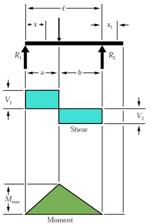
The overhanging beam, unlike the simple or fixed beam, has one end that is unsupported.
The overhanging beam has the first support at the beam’s end while the second support is located along the beam toward the center. In this particular example, the portion of the beam that passes the second support does not experience shear or bending. The visual depiction of shear and bending is similar to the simple beam. However, since the example above does not have a center load, the shear calculations will be different for each support:
R1= V1 = P.b/l
(max shear value when a < b)
R2 = V2 = P.a/l
(Maximum shear value when a > b)
Maximum moment is calculated by the following equation:
Mmax = P.ab/l
Double Overhanging Beam
Both ends in the image above are unsupported. The double overhanging beam instead has supports located towards the center of the beam.
The double overhanging beam is the same concept as the single, except with both supports located along and within the beams length. In this case, the load across the beam is a uniformed load and impacts the shear and bending diagrams in a more complicated way. From left to right, the first shear value is determined by the distance of the first support to the end multiplied by the uniformed load.
V1=wa
The reaction load at the first support is determined by:
R1 = w l (l-2c)/2b
Where b and c are distances between supports and the remaining edge distance, respectively.
The shear value then changes at the first support location and is determined by the difference between the first shear value and the first support load:
V2=R1 – V1
Continuing left to right, the reaction load at the second support is:
R2 = w l (1-2a)/2b
Now the third shear value can be calculated as:
V3=R2-V4
Where V4 is the shear caused by the uniformed load at the right side overhanging edge:
V4=w.c
The momentum profile is much different in this case. As a result of the support locations, three different momentums take place. Using the same principle as we did for shear, we can analyze the moment values from left to right. The first bending moment is calculated simply by:
M1=-wa2/2
The next moment, which is M3 in the example above, is calculated with the following equation:
M3 = R1 (R1/2w – a)
The final moment, M2, is determined by:
M2=-wc2 / 2
These are the three moments acting on the beam for this case. Maximum moment is determined by:
Mmax = R1x- w (a + x ) 2 /2
Where x = R1/w – a
Relationship between Load, Shear, and Moment
The vertical shear at C in the figure is taken as
VC= (ΣFv) L=R1−wx
Where R1 = R2 = w.L/2
Vc =wL2−wxVc=wL2−wx
The moment at C is
MC= (ΣMC) =wLx/2−wx(x/2)
MC=wLx/2−wx2 /2
If we differentiate M with respect to x:
dM/dx=wL/2⋅dx/dx−w/2(2x⋅dx/dx)
DM/dx=wL/2−wx=shear
Thus,
DM/dx=V
Thus, the rate of change of the bending moment with respect to x is equal to the shearing force, or the slope of the moment diagram at the given point is the shear at that point
Differentiate V with respect to x gives
dV/dx=0−w
thus,
DV/ dx=Load
Thus, the rate of change of the shearing force with respect to x is equal to the load or the slope of the shear diagram at a given point equal at the point
Properties of Shear and Moment Diagrams
The following are some important properties of shear and moment diagrams:
- The area of the shear diagram to the left or to the right of the section is equal to the moment at that section.
- The slope of the moment diagram at a given point is the shear at that point.
- The slope of the shear diagram at a given point equals the load at that point.
 The maximum moment occurs at the point of zero shears. This is in reference to property number 2, that when the shear (also the slope of the moment diagram) is zero, the tangent drawn to the moment diagram is horizontal.
- When the shear diagram is increasing, the moment diagram is concave upward.
- When the shear diagram is decreasing, the moment diagram is concave downward.
Sign Convention
The customary sign conventions for shearing force and bending moment are represented by the figures below. A force that tends to bend the beam downward is said to produce a positive bending moment. A force that tends to shear the left portion of the beam upward with respect to the right portion is said to produce a positive shearing force.
An easier way of determining the sign of the bending moment at any section is that upward forces always cause positive bending moments regardless of whether they act to the left or to the right of the exploratory section.
A shearing force occurs when a perpendicular force is applied to static material (in this case a beam). Think of a knife cutting through a carrot. Imagine the beam is the carrot and a point load is the knife. As the knife applies a downward force, it cuts (or shears) the carrot. These forces occur along numerous points of a beam, and it is important to determine where these shears are at the greatest points as this may be where a beam fails.
To calculate the shear forces of a beam, follow the following simple steps:
1. Start with the far left side of the beam
If there is an upward force (i.e a support) then the SFD will start at this force above the x-axis. If there is a downward point load and no support, than the shear force diagram will start as a negative at the value of the point load.
Move across the beam
As you come across loads, you simply add (or subtract) these loads from the value you already have, keeping a cumulative total.
It is much easier to understand when considering an example of a how to calculate a Shear Force Diagram. So let's consider the following example to calculate the shear force diagram of a beam:

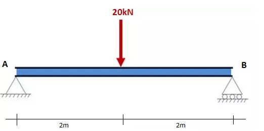

Step 1: After calculating the reactions at A and B, start the Shear Force Diagram at the first value of the force acting on the beam. In this case it is a +10kN due to the reaction at point A:

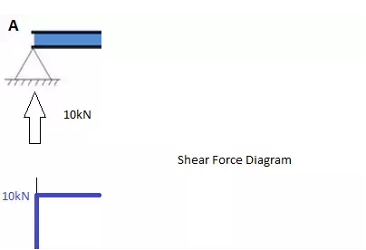
Step 2: Keep moving across the beam, stopping at every load that acts on the beam. When you get to a load, add to the Shear Force Diagram by the amount of the force. In this case we have come to a negative 20kN force, so we will minus 20kN from the existing 10kN. i.e. 10kN - 20kN = -10kN.
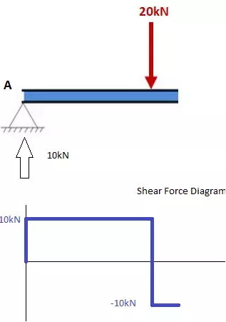
Moving across the beam again, we come to another force; a positive 10kN reaction at support B. Again, add this +10kN to the shear force diagram (which is currently at -10kN) which will bring us to a shear force of 0. Since we are at the end of the beam, we will go no further and we have our final Shear Force Diagram (SFD):
Things to keep in mind:
- The area under the SFD above the x axis should equal the area between the x-axis and the SFD below the x axis. i.e the area should sum to zero. Check this is true in our above example.
- Any points where the SFD cross the x-axis, will be a max or min Bending Moment
- The SFD should always equal zero at both ends.
How to Calculate the Bending Moment Diagram of a Beam
Below are simple instructions on how to calculate the bending moment diagram of a simple supported beam. Study this method as it is very versatile (and can be adapted to many different types of problem. The ability to calculate the bending moment of a beam is very common practice for structural engineers and often comes up in college and high school exams.
Firstly, what is a Bending Moment? A moment is rotational force that occurs when a force is applied perpendicularly to a point at a given distance away from that point. It is calculated as the perpendicular force multiplied by the distance from the point. A Bending Moment is simply the bend that occurs in a beam due to a moment. It is important to remember two things when calculating bending moments; (1) the standard units are Nm and (2) clockwise bending is taken as negative. Anyways, with the boring definitions out of the way, let's look at the steps to calculate a bending moment diagram:
1. Calculate reactions at supports and draw Free Body Diagram (FBD).
If you're not sure how to do this, click here for our tutorial. Once you have the reactions, draw your Free Body Diagram and Shear Force Diagram underneath the beam:
2. From left to right, make "cuts" before and after each reaction/load
TO calculate the bending moment of a beam, we must work in the same way we did for the Shear Force Diagram. Starting at x = 0 we will move across the beam and calculate the bending moment at each point
Cut 1
Make a "cut" just after the first reaction of the beam. In our simple example:
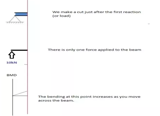
So, when we cut the beam, we only cosider the forces that are applied to the left of our cut. In this case we have a 10kN force in the upward direction. Now as you recall, a bending moment is simply the force x distance. So as we move further from the force, the magnitude of the bending moment will increase. We can see this in our BMD. The equation for this part of our bending moment diagram is:
-M(x) = 10(-x)
M(x) = 10x
Cut 2
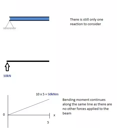

This cut is made just before the second force along the beam. Since there are no other loads applied between the first and second cut, the bending moment equation will remain the same. This means we can calculate the maximum bending moment (in this case at the midpoint, or x = 5) by simply substituting x=5 into the above equation:

Cut 3
This cut is made just after the second force along the beam. Now we have TWO forces that act to the left of our cut: a 10kN support reaction and a -20kN downward acting load. So now we must consider both these forces as we progress along our beam. For every metre we move across the beam, there will a +10kNm moment added from the first force and -20kNm from the second. So after the point x=5, our Bending Moment Equation becomes:
M(x) = 50 +10(x-5) - 20(x-5)
M(x) = 50 -10(x-5) for 5 ≤ x ≤ 10
NOTE: The reason we write (x-5) is because we want to know the distance from the pt x=5 only. Anything before this point uses a previous equation.
Cut 4
Again, let's move across to the right of our beam and make a cut just before our next force. In this case, our next cut will occur just before the reaction from Right Support. Since there are no other forces between the support and our previous cut, the equation will remain the same:
M(x) = 50 -10(x-5) for 5 ≤ x≤ 10
And let's substitute x=10 into this to find the find bending moment at the end of the beam:
M(x) = 50 - 10(10-5) = 0kNm
Variation of Shear force and bending moments:
Variation of Shear force and bending moments for various standard loads are as shown in the following Table
Type of load
SFD/BMD | Between point loads OR for no load region | Uniformly distributed load | Uniformly varying load |
Shear Force Diagram | Horizontal line | Inclined line | Two-degree curve (Parabola) |
Bending Moment Diagram | Inclined line | Two-degree curve (Parabola) | Three-degree curve (Cubic-parabola) |
Question - Find the support reactions of given beam for loading as shown below.
 Draw FBD of given beam & applying conditions of equilibrium
∑fx = 0
RHA = 0
∑fxy = 0
RVA – 20 + RB = 0
RVA + RB = 20 ------(1)
Taking moments at A
∑MA = 0
(20 × 3) – (RB × 5) = 0
60 – 5RB

RB = 12 kN  put in equation (1)
 RVA + 12 = 20
 RVA = 20-12 = RVA = 8 kN