External Communication Interface
Serial data can be sent by two ways which are
1. Synchronous communication
2. Asynchronous communication
In synchronous transmission, data are transmitted in block at a constant rate. The start and end of a block are identified with specific bytes or bit patterns.
|
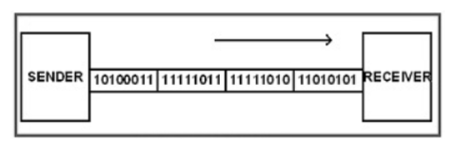
Figure 1. Synchronous transmission
There is no clock involved here and transmission is synchronized by special signals along the transmission medium. It transfers a single byte at a time between sender and receiver along with inserting a start bit before each data character and a stop bit at its termination so that to inform the receiver where the data begins and ends.
|
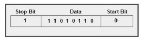
Figure 2. Asynchronous data transmission
Key Take Aways:
Synchronous and Aynchronous data transmission are used in 8051 serial communication.
RS232 is a standard protocol used for serial communication which is used for connecting computer and its peripheral devices for serial data exchange between them.
RS232 is used for connecting Data Transmission Equipment (DTE) and Data Communication Equipment (DCE).
|
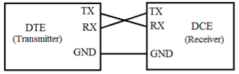
Figure 3. RS-232
Universal Asynchronous Data Receiver &Transmitter (UART) used in connection with RS232 for transferring data between printer and computer. The microcontrollers are not able to handle such kind of voltage levels, connectors are connected between RS232 signals. These connectors are known as the DB-9 Connector as a serial port and they are of two type’s Male connector (DTE) & Female connector (DCE).
Key Take Aways:
RS232 is one of the most widely used techniques to interface external equipment with computers.
The Inter-Integrated Circuit (I2C) Protocol allows multiple "peripheral" digital integrated circuits or "chips" to communicate with one or more "controller" chips. Like SPI, it is used for short distance communications within a single device. Like RS-232 it only requires two signal wires to exchange information.
|
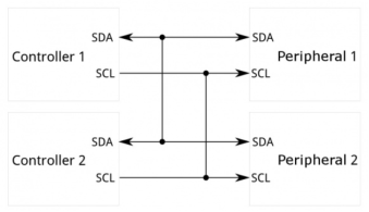
Figure4 . I2C communication
I2C requires two wires like asynchronous serial which can support up to 1008 peripheral devices.
I2C can support a multi-controller system allowing more than one controller to communicate with all peripheral devices on the bus.
Data rates fall between asynchronous serial and SPI; most I2C devices can communicate at 100kHz or 400kHz.
The hardware required to implement I2C is more complex than SPI, but less than asynchronous serial. It can be trivially implemented in software.
Key Take Aways:
It is a serial communications protocol similarly to UART but not used for PC-device communication but are used with modules and sensors.
|
Figure 5. Zigbee Block Diagram
The figure shows how to interface the Zigbee with microcontroller.
The Xbee modules work at the 2.4 GHz frequency. Xbee modules can transmit Digital, PWM, Analog or Serial RS232 signals wirelessly.
To communicate over UART or USART three basic signals are required which are namely, RXD (receive), TXD (transmit), GND (common ground).
|
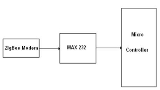
Figure 6. Zigbee Interfacing
To interface ZigBee module with 8051 Development Board for accessing the mobiles without wires can be done through UART0. The data communication is done in internet by using the ZigBee module through MAX232 into the SBUF register of 8051 microcontrollers.
The serial data from the Zigbee receiver is taken by using the Serial Interrupt of the controller. +5V and ground is connected to provide power to the module. While TX and RX pin is connected for communication.
|
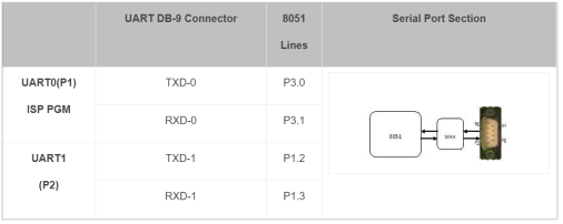
Figure. Pin Assignment
|
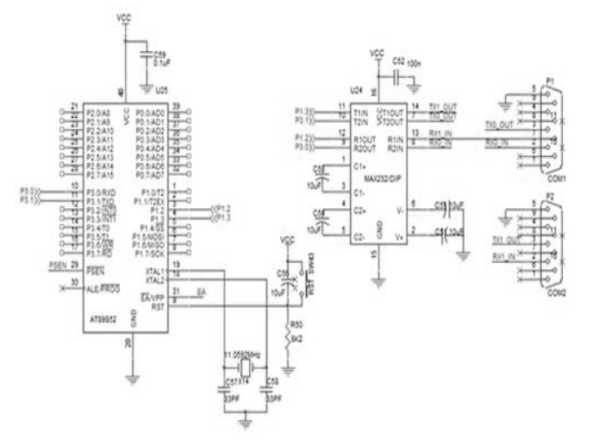
Figure 7. Interfacing Zigbee with 8051 microcontroller
#include //Define 8051 Registers void serial(void); //Serial Communication Register void DelayMs(unsigned int); //Delay Function unsigned int i,j; unsigned char b[25],d; //--------------------------- // Main Program //--------------------------- void main() { EA=1; //Enable All Interrupt ES=1; //Enable Serial Port Interrupt serial(); //Serial Communication while(1); //Loop Forever } //------------------------------------------ // Serial Communication Register Initialisation
//------------------------------------------
void serial(void) { TMOD=0X20; //Timer1, Mode2 SCON=0X50; //Serial Mode1, Receive Enable TH1=0XFD; //Baud Rate 9600bps TR1=1; //Timer1 ON } //----------------------------------------- // Serial Interrupt Function //----------------------------------------- void serin (void) interrupt 4 //Serial Port Interrupt { if(RI==1) //Receive Interrupt Gets Enabled { //after Stop Bit get Received d=SBUF; //Serial Buffer value moved to a variable b[j]=d; SBUF=b[j]; DelayMs(20); //Delay Function j++; } SCON=0X50; //Initialising Receive and Transmit Interrupt } //--------------------------------- // Delay Function //--------------------------------- void DelayMs(unsigned int k) { unsigned int i; for(i=0;i<=k;i++); }
|
- Bluetooth
The devices such as mobile and PC’s need special applications known as “Bluetooth Terminal” to communicate with our microcontrollers via Bluetooth.
|
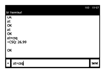
Figure8. BT terminal Application
These applications are developed in such a way to send characters through your device BT which was received by the BT module connected with the controller.
|
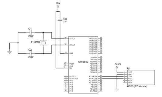
Figure9. Interfacing with 8051 microcontroller
Programming Steps:
- This uses Serial Communication or UART protocol in 8051.
- Initialize the Serial communication in 8051 using Timer and serial registers.
- Generate the required baud rate for the communication to take place. The default baud rate of the HC05 is 9600.
- Initialize serial interrupts to take control of the tasks performed by microcontroller or receive data when requested.
Program:
int a,b,ans;
char rec[4];
void main()
{
a=80;
b=40;
ans=a+b;
sprintf(rec, "%d", ans);
TMOD=0x20; //Choosing Timer mode
TH1=0xFD; //Selecting Baud Rate
SCON=0x50; //Serial mode selection
TR1=1;
IE=0x90; //Enabling Serial Interrupt
while(1);
}
void ser_intr(void)interrupt 4 //Subroutine for Interrupt
{
IE=0x00;
short int i;
for(i=0;i<=2;i++) //Transmitting data
{
SBUF=rec[i];
while(TI==0);
TI=0;
}
IE=0x90;
}
Key Takeaways:
HC-05 is a Bluetooth device used for wireless communication. It works on serial communication (UART).
References
- The 8051 Microcontroller and Embedded Systems using Assembly and C by Muhammad Ali Mazidi.
- The 8051 Microcontroller by I. Scott Mackenzie, Raphael C.W Phan
8051 Microcontrollers: Internals, Instructions, Programming, and Interfacing Book by Subrata Ghoshal


