Unit-6
Applications
Light Emitting Diodes are the semi- conductor light sources. Commonly used LEDs will have a cut-off voltage of 1.7V and current of 10mA. When an LED is applied with its required voltage and current it glows with full intensity.
The Light Emitting Diode works similar to normal PN- diode but it emits energy in the form of light. The color of light depends on the band gap of the semiconductor.
|
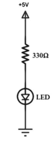
Figure 1. LED
LED is connected to AT89C51 microcontroller with the help of a current limiting resistor. The value of this resistor is calculated using the following formula.
R= (V-1.7)/10mA, where V is the input voltage.
The maximum output voltage of microcontrollers is 5V. Thus, the value of resistor calculated for this is 330 Ohms. The resistor can be connected to either the cathode or the anode of the LED.
- Initially, burn the code into the microcontroller.
- Connect the LEDs to the Port0 of the microcontroller.
- Switch on the circuit.
- The LEDs start glowing.
- Now, switch off the circuit.
- Initially, include the “reg51.h” header file in your code.
- Now write a function to produce delay using for loop.
- Start the main function.
- Inside the while loop write the condition to port pin for making it logic high or low.
- Initially, make it high for some delay of 1000 microseconds.
- Now make the port pin low.
- Again, provide some delay of 1000 microseconds.
- Repeat this for 8 times using for loop.
- In another loop, try to represent the binary equivalent of the first 255 number using LEDs.
- Now close the while loop and end main.
Applications
- LEDs are widely used in many applications like in seven segments.
- They are used in dot matrix displays.
- They can be used for streetlights.
- They are used as indicators.
- They can be used in traffic lights.
- They are used in emergency lights
- They can have used to make electronic designs.
Key Take Aways:
LED is a semiconductor device used mainly in electronic devices, for signal transmission /power indication purposes.
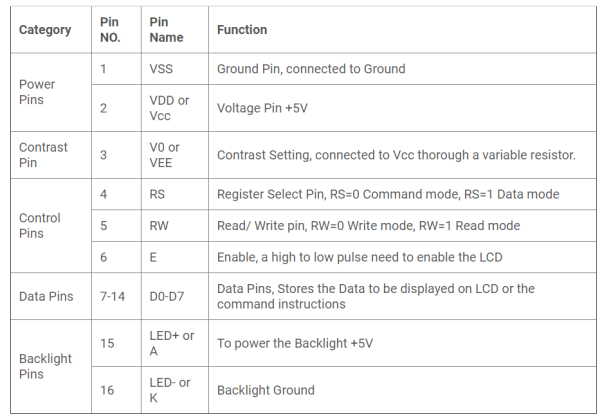
LCD is one of the most used display unit. 16x2 LCD means that there are two rows in which 16 characters can be displayed per line, and each character takes 5X7 matrix space on LCD.
We can divide it in five categories, Power Pins, contrast pin, Control Pins, Data pins and Backlight pins.
|
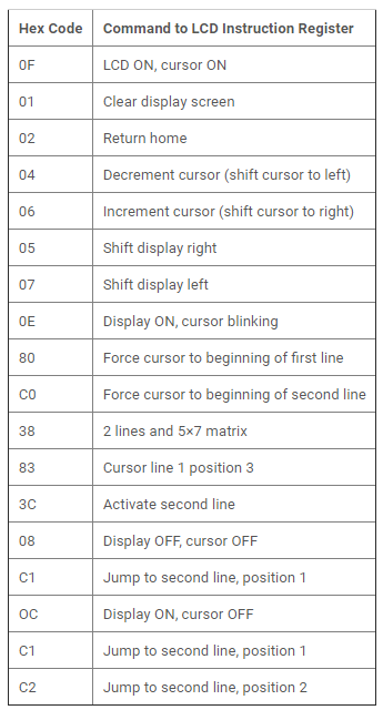
RS: RS is the register select pin. If set it to 1 we are sending some data to be displayed on LCD. If set it to 0 some command instruction like clear the screen (hex code 01).
RW: This is Read/write pin, If set it to 0, we write some data on LCD. And if set to 1 we read from LCD module. Generally, this is set to 0, because we do need to read data from LCD.
E: This pin is used to enable the module when a high to low pulse is given to it. That transition from HIGH to LOW makes the module ENABLE.
Some important command instructions are given below:
|
|
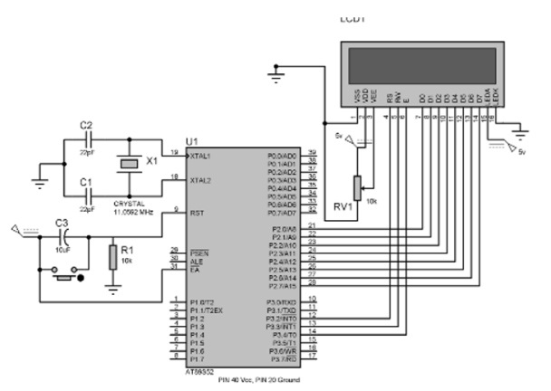
Figure 2. LCD Interfacing
LCD interfacing with 8051 microcontrollers is shown in the above figure.
The data pins (D0-D7) of LCD to the Port 2 (P2_0 – P2_7) microcontroller. And control pins RS, RW and E to the pin 12,13,14 (pin 2,3,4 of port 3) of microcontroller, respectively.
PIN 2(VDD) and PIN 15(Backlight supply) of LCD are connected to voltage (5v), and PIN 1 (VSS) and PIN 16(Backlight ground) are connected to ground.
Pin 3(V0) is connected to voltage (Vcc) through a variable resistor of 10k to adjust the contrast of LCD. Middle leg of the variable resistor is connected to PIN 3 and other two legs are connected to voltage supply and Ground.
Program:
/ Program for LCD Interfacing with 8051 Microcontroller (AT89S52) #include<reg51.h> #define display_port P2 //Data pins connected to port 2 on microcontroller sbit rs = P3^2; //RS pin connected to pin 2 of port 3 sbit rw = P3^3; // RW pin connected to pin 3 of port 3 sbit e = P3^4; //E pin connected to pin 4 of port 3 void msdelay(unsigned int time) // Function for creating delay in milliseconds. { unsigned i,j ; for(i=0;i<time;i++) for(j=0;j<1275;j++); } void lcd_cmd(unsigned char command) //Function to send command instruction to LCD { display_port = command; rs= 0; rw=0; e=1; msdelay(1); e=0; } void lcd_data(unsigned char disp_data) //Function to send display data to LCD { display_port = disp_data; rs= 1; rw=0; e=1; msdelay(1); e=0; } void lcd_init() //Function to prepare the LCD and get it ready { lcd_cmd(0x38); // for using 2 lines and 5X7 matrix of LCD msdelay(10); lcd_cmd(0x0F); // turn display ON, cursor blinking msdelay(10); lcd_cmd(0x01); //clear screen msdelay(10); lcd_cmd(0x81); // bring cursor to position 1 of line 1 msdelay(10); } void main() { unsigned char a[15]="CIRCUIT DIGEST"; //string of 14 characters with a null terminator. int l=0; lcd_init(); while(a[l] != '\0') // searching the null terminator in the sentence { lcd_data(a[l]); l++; msdelay(50); } }
|
Key Take Aways:
16x2 LCD means that there are two rows in which 16 characters can be displayed per line, and each character takes 5X7 matrix space on LCD.
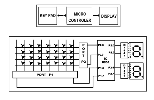
Matrix keyboard is used for interfacing. It is designed with a rows and columns. These rows and columns are connected to the microcontroller through its ports of 8051. .
Whenever a key is pressed, a row and a column get shorted through that pressed key and all the other keys are left open. The bit in the port goes high which indicates the microcontroller that the key is pressed. By this high on the bit key in the corresponding column is identified.
Once we are sure that one of key in the keyboard is pressed next our aim is to identify that key. To do this we firstly check particular row and then check the corresponding column on the keyboard.
In order to check the row of the pressed key, one of the rows is made high by making one of bit in the output port of 8051 high. This is done until the row is found out. Once we get the row the next task is to detect the column of the pressed key. The column is detected by contents in the input ports with the help of a counter. The content of the input port is rotated with carry until the carry bit is set.
The contents of the counter is compared and displayed in the display. This display is seven segment display and a BCD to seven segment decoder IC 7447.
The BCD equivalent to the number of counter is sent through output part of 8051 displays the number of pressed key.
|
Figure 3. Keyboard interfacing with 8051
Steps:
1.8051 has 4 I/O ports P0 to P3 each with 8 I/O pins, P0.0 to P0.7,P1.0 to P1.7, P2.0 to P2.7, P3.0 to P3.7. The one of the ports P1 means P1.0 to P1.7 serve as an i/p port for 8051. Port P0 serves as an o/p port of 8051 and port P2 is used for displaying the number of pressed key.
2.Make all rows of port P0 high so that it gives high signal when key is pressed.
3.See if any key is pressed by scanning port P1 and by checking all columns for non- zero condition.
4.If any key is pressed, then identify which key is pressed make one row high at a time.
5.Initiate a counter to hold the count so that each key is counted.
6.Check port P1 for nonzero condition. If any nonzero number is there in [accumulator], start column scanning by following step 9.
7.Otherwise make next row high in port P1.
8.Add a count of 08h to the counter to move to the next row by repeating steps from step 6.
9.If any key pressed is found, the [accumulator] content is rotated right through the carry until carry bit sets, while doing this increment the count in the counter till carry is found.
10. Move the content in the counter to display in data field or to memory location
11.To repeat the procedures, go to step 2.
Program:
Start of main program: to check that whether any key is pressed start: mov a,#00h mov p1,a ;making all rows of port p1 zero mov a,#0fh mov p1,a ;making all rows of port p1 high press: mov a,p2 jz press ;check until any key is pressed
after making sure that any key is pressed
mov a,#01h ;make one row high at a time mov r4,a mov r3,#00h ;initiating counter next: mov a,r4 mov p1,a ;making one row high at a time mov a,p2 ;taking input from port A jnz colscan ;after getting the row jump to check column mov a,r4 rl a ;rotate left to check next row mov r4,a mov a,r3 add a,#08h ;increment counter by 08 count mov r3,a sjmp next ;jump to check next row
after identifying the row to check the column following steps are followed
colscan: mov r5,#00h in: rrc a ;rotate right with carry until get the carry jc out ;jump on getting carry inc r3 ;increment one count jmp in out: mov a,r3 da a ;decimal adjust the contents of counter before display mov p2,a jmp start ;repeat for check next key. |
Key Take Aways:
The keyboard is designed with a particular rows and columns. These rows and columns are connected to the microcontroller through its ports of the micro controller 8051.
Stepper motors is mainly used to translate electrical pulses into mechanical movements.
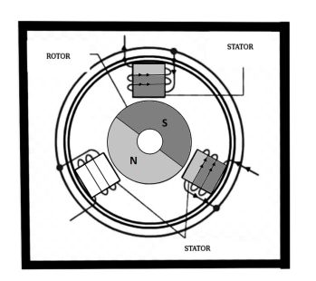
Stepper motors generally have a permanent magnet shaft (rotor), and it is surrounded by a stator.
|
|
|
| Figure4: Stepper Motor |
|
|
|
|
Parameters of stepper motors:
- Step Angle - The step angle is the angle at which the rotor moves when one pulse is applied as an input of the stator. This parameter is used to determine the positioning of a stepper motor.
- Steps per Revolution - This is the number of step angles required for a complete revolution. The formula is 360° /Step Angle.
- Steps per Second - This parameter is used to measure number of steps covered in each second.
- RPM - The RPM is the Revolution Per Minute. It measures the frequency of rotation. We can measure the number of rotations in one minute.
The relation between RPM steps per revolution and steps per second is
Steps per second = rpm x steps per revolution / 60
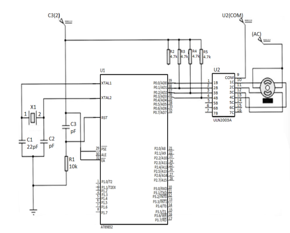
Port P0 of 8051 is used for connecting the stepper motor. HereULN2003 is used. This is basically a high voltage, high current Darlington transistor array. Each ULN2003 has seven NPN Darlington pairs. It can provide high voltage output with common cathode clamp diodes for switching inductive loads.
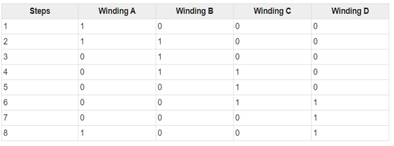
The Unipolar stepper motor works in three modes.
- Wave Drive Mode: In this mode, one coil is energized at a time. So all four coils are energized one after another. This mode produces less torque than full step drive mode.
|
Full Drive Mode: In this mode, two coils are energized at the same time. This mode produces more torque. Here the power consumption is also high.
|
Half Drive Mode: In this mode, one and two coils are energized alternately. At first, one coil is energized then two coils are energized. This is basically a combination of wave and full drive mode. It increases the angular rotation of the motor.
|
|
Figure 5. Interfacing Stepper Motor with 8051
Program:
#include<reg51.h> sbit LED_pin = P2^0; //set the LED pin as P2.0 void delay(int ms){ unsigned int i, j; for(i = 0; i<ms; i++){ // Outer for loop for given milliseconds value for(j = 0; j< 1275; j++){ //execute in each milliseconds ; } } } void main(){ int rot_angle[] = {0x0C,0x06,0x03,0x09}; int i; while(1){ //infinite loop for LED blinking for(i = 0; i<4; i++){ P0 = rot_angle[i]; delay(100); } } }
|
Key Take Aways:
Stepper motors are used to translate electrical pulses into mechanical movements. The main advantage of using the stepper motor is the position control. Stepper motors generally have a permanent magnet shaft (rotor), and it is surrounded by a stator.
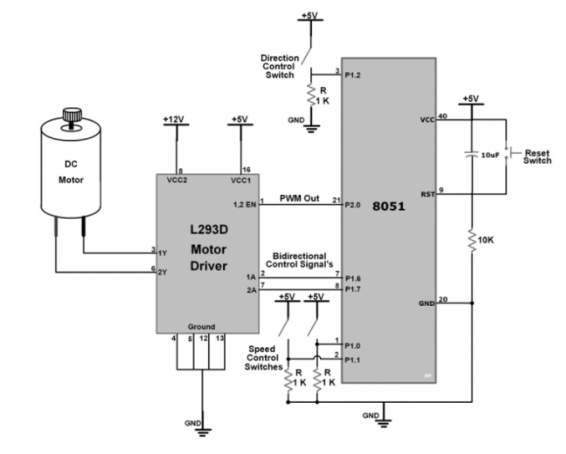
DC motor converts electrical energy in the form of Direct Current into mechanical energy.
|
Figure 6. DC Motor Interfacing
- As shown in the above figure we have connected two toggle switches on P1.0 and P1.1 pin of the AT89S52 microcontroller to change the speed of the DC motor by 10%.
- One toggle switch at pin P1.2 controls the motor rotating direction.
- P1.6 and P1.7 pins are used as output direction control pins. It provides control to motor1 input pins of L293D motor driver which rotate the motor clockwise and anticlockwise by changing their terminal polarity.
- And Speed of the DC Motor is varied through PWM Out pin P2.0.
- The timer of AT89S52 is used to generate PWM.
Program
#include <reg52.h> #include <intrins.h> /* Define value to be loaded in timer for PWM period of 20 milli second */ #define PWM_Period 0xB7FE sbit PWM_Out_Pin = P2^0; /* PWM Out Pin for speed control */ sbit Speed_Inc = P1^0; /* Speed Increment switch pin */ sbit Speed_Dec = P1^1; /* Speed Decrement switch pin */ sbit Change_Dir = P1^2; /* Rotation direction change switch pin */ sbit M1_Pin1 = P1^6; /* Motor Pin 1 */ sbit M1_Pin2 = P1^7; /* Motor Pin 2 */ unsigned int ON_Period, OFF_Period, DutyCycle, Speed; /* Function to provide delay of 1ms at 11.0592 MHz */ void delay(unsigned int count) { int i,j; for(i=0; i<count; i++) for(j=0; j<112; j++); } void Timer_init() { TMOD = 0x01; /* Timer0 mode1 */ TH0 = (PWM_Period >> 8);/* 20ms timer value */ TL0 = PWM_Period; TR0 = 1; /* Start timer0 */ } /* Timer0 interrupt service routine (ISR) */ void Timer0_ISR() interrupt 1 { PWM_Out_Pin = !PWM_Out_Pin; if(PWM_Out_Pin) { TH0 = (ON_Period >> 8); TL0 = ON_Period; } else { TH0 = (OFF_Period >> 8); TL0 = OFF_Period; }
}
/* Calculate ON & OFF period from PWM period & duty cycle */ void Set_DutyCycle_To(float duty_cycle) { float period = 65535 - PWM_Period; ON_Period = ((period/100.0) * duty_cycle); OFF_Period = (period - ON_Period); ON_Period = 65535 - ON_Period; OFF_Period = 65535 - OFF_Period; }
/* Initially Motor Speed & Duty cycle is zero and in either direction */ void Motor_Init() { Speed = 0; M1_Pin1 = 1; M1_Pin2 = 0; Set_DutyCycle_To(Speed); }
int main() { EA = 1; /* Enable global interrupt */ ET0 = 1; /* Enable timer0 interrupt */ Timer_init(); Motor_Init(); while(1) { /* Increment Duty cycle i.e. speed by 10% for Speed_Inc Switch */ if(Speed_Inc == 1) { if(Speed < 100) Speed += 10; Set_DutyCycle_To(Speed); while(Speed_Inc == 1); delay(200); } /* Decrement Duty cycle i.e. speed by 10% for Speed_Dec Switch */ if(Speed_Dec == 1) { if(Speed > 0) Speed -= 10; Set_DutyCycle_To(Speed); while(Speed_Dec == 1); delay(200); } /* Change rotation direction for Change_Dir Switch */ if(Change_Dir == 1) { M1_Pin1 = !M1_Pin1; M1_Pin2 = !M1_Pin2; while(Change_Dir == 1); delay(200); } } }
|
Key Take Aways:
In the case of the motor, the mechanical energy produced is in the form of a rotational movement of the motor shaft. The direction of rotation of the shaft of the motor can be reversed by reversing the direction of Direct Current through the motor.
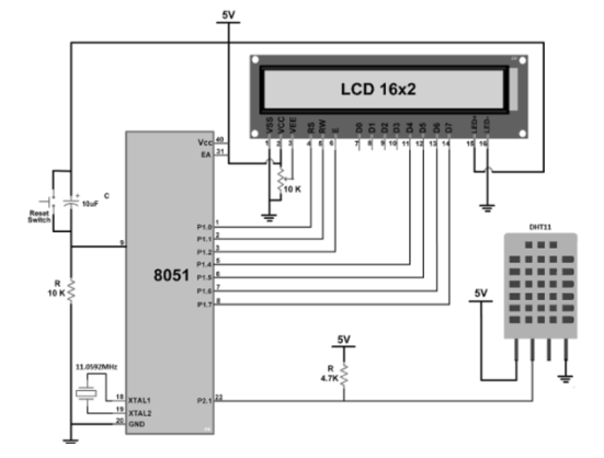
DHT11 is a single wire digital humidity and temperature sensor, which provides humidity and temperature values serially.
|
Figure 7. Sensor Interfacing
- The above circuit diagram shows the interfacing of 8051 with the DHT11 sensor.
- In that, a DHT11 sensor is connected to P2.1(Pin No 22) of the microcontroller.
Programming Steps
- First, initialize the LCD16x2_4bit.h library.
- Define pin no. to interface DHT11 sensor, in our program we define P2.1 (Pin no.22)
- Send the start pulse to the DHT11 sensor by making low to high on the data pin.
- Receive the response pulse from the DHT11 sensor.
- After receiving the response, receive 40-bit data serially from the DHT11 sensor.
- Display this received data on LCD16x2 along with error indication.
#include<reg51.h> #include<stdio.h> #include<string.h> #include <stdlib.h> #include "LCD16x2_4bit.h"
sbit DHT11=P2^1; /* Connect DHT11 output Pin to P2.1 Pin */ int I_RH,D_RH,I_Temp,D_Temp,CheckSum;
void timer_delay20ms() /* Timer0 delay function */ { TMOD = 0x01; TH0 = 0xB8; /* Load higher 8-bit in TH0 */ TL0 = 0x0C; /* Load lower 8-bit in TL0 */ TR0 = 1; /* Start timer0 */ while(TF0 == 0); /* Wait until timer0 flag set */ TR0 = 0; /* Stop timer0 */ TF0 = 0; /* Clear timer0 flag */ }
void timer_delay30us() /* Timer0 delay function */ { TMOD = 0x01; /* Timer0 mode1 (16-bit timer mode) */ TH0 = 0xFF; /* Load higher 8-bit in TH0 */ TL0 = 0xF1; /* Load lower 8-bit in TL0 */ TR0 = 1; /* Start timer0 */ while(TF0 == 0); /* Wait until timer0 flag set */ TR0 = 0; /* Stop timer0 */ TF0 = 0; /* Clear timer0 flag */ }
void Request() /* Microcontroller send request */ { DHT11 = 0; /* set to low pin */ timer_delay20ms(); /* wait for 20ms */ DHT11 = 1; /* set to high pin */ }
void Response() /* Receive response from DHT11 */ { while(DHT11==1); while(DHT11==0); while(DHT11==1); }
int Receive_data() /* Receive data */ { int q,c=0; for (q=0; q<8; q++) { while(DHT11==0);/* check received bit 0 or 1 */ timer_delay30us(); if(DHT11 == 1) /* If high pulse is greater than 30ms */ c = (c<<1)|(0x01);/* Then its logic HIGH */ else /* otherwise its logic LOW */ c = (c<<1); while(DHT11==1); } return c; }
void main() { unsigned char dat[20]; LCD_Init(); /* initialize LCD */
while(1) { Request(); /* send start pulse */ Response(); /* receive response */
I_RH=Receive_data(); /* store first eight bit in I_RH */ D_RH=Receive_data(); /* store next eight bit in D_RH */ I_Temp=Receive_data(); /* store next eight bit in I_Temp */ D_Temp=Receive_data(); /* store next eight bit in D_Temp */ CheckSum=Receive_data();/* store next eight bit in CheckSum */
if ((I_RH + D_RH + I_Temp + D_Temp) != CheckSum) { LCD_String_xy(0,0,"Error"); }
else { sprintf(dat,"Hum = %d.%d",I_RH,D_RH); LCD_String_xy(0,0,dat); sprintf(dat,"Tem = %d.%d",I_Temp,D_Temp); LCD_String_xy(1,0,dat); LCD_Char(0xDF); LCD_String("C"); memset(dat,0,20); sprintf(dat,"%d ",CheckSum); LCD_String_xy(1,13,dat); } delay(100); } }
|
Key Take Aways:
DHT11 can measure the relative humidity in percentage (20 to 90% RH) and temperature in degree Celsius in the range of 0 to 50°C.
References :
- The 8051 Microcontroller and Embedded Systems using Assembly and C by Muhammad Ali Mazidi.
- The 8051 Microcontroller by I. Scott Mackenzie, Raphael C.W Phan
8051 Microcontrollers: Internals, Instructions, Programming, and Interfacing Book by Subrata Ghoshal
