Module 2
Modulation
The other type of Analog modulation is Angle Modulation. When the frequency or the phase of the carrier signal varies according to the message signal, this process is known as Angle Modulation.
The equation of the angle modulated wave is given by,
s(t)=Accosθi(t)
Where,
Ac: amplitude of the modulated wave, as well as the amplitude of the carrier signal
θi (t) : angle of the modulated wave
There are two types of Angle modulation
- Frequency Modulation In this process the frequency of the carrier signal varies in accordance with the message signal.
- Phase Modulation In this process the phase of the carrier signal varies with the message signal.
In Frequency Modulation (FM), the frequency of the carrier signal varies with respect to the instantaneous amplitude of the modulating signal.
Hence, the amplitude and the phase of the carrier signal are constant in FM . Wave forms of FM are as shown in fig below.,
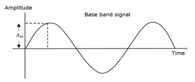
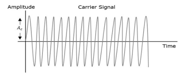
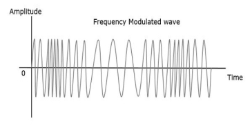
When the amplitude of the baseband signal or message signal increases, the frequency of the modulated wave also increases. Similarly, when the amplitude of the baseband signal or message signal decreases, the frequency of the modulated wave also decreases. And when amplitude of baseband signal is zero, then frequency of modulated wave remains unchanged i.e. it is equal to frequency of carrier signal.
Mathematical Expression
The equation for frequency fi in FM modulation is
fi = fc + kf m(t)
Where,
fc: carrier frequency
kt: frequency sensitivity
m(t): message signal
We know that the relation between angular frequency ωi and angle θi(t) as
ωi = 
2πfi = 
θi(t)=2π 
Put the value of  in the above equation.
θi(t) = 2π 
θi(t) = 2πfct + 2πkf 
Put the value of θi(t) in the standard equation of angle modulated wave.
s(t)=Accos (2πfct + 2πkf  )
)
This equation is of FM wave.
If the baseband/modulating signal is m(t)= Amcos(2πfmt), then the equation of FM wave becomes
s(t)=Accos (2πfct + 2πkf  )
)
s(t)=Ac cos (2πfct + βsin(2πfmt))
Where,
β = modulation index =  =
= 
Δf is the Frequency Deviation, is given by the difference between FM modulated frequency and carrier frequency which is equal to the product of kf and Am.
Based on the values of modulation index β, FM can be divided into Narrowband FM and Wideband FM.
Narrowband FM
Features of Narrowband FM are,
- This frequency modulation has a small bandwidth as compared to wideband FM.
- The modulation index β is small, i.e., < 1.
- Narrowband spectrum consists of the carrier, the upper sideband and the lower sideband.
- Narrowband FM is used in mobile communications such as police wireless, ambulances, taxicabs, etc.
Wideband FM
Features of Wideband FM are,
- This frequency modulation has infinite bandwidth.
- The modulation index β is large, i.e., > 1.
- Wideband spectrum consists of a carrier and infinite number of sidebands, which are located around it.
- Wideband FM is used in entertainment, broadcasting applications such as FM radio, TV, etc.
The frequency of the carrier varies in FM. Whereas, in Phase Modulation (PM), the phase of the carrier signal varies with respect to the instantaneous amplitude of the modulating signal.
So, in phase modulation, the amplitude and the frequency of the carrier signal are constant. Wave forms of PM are as shown in fig below.,
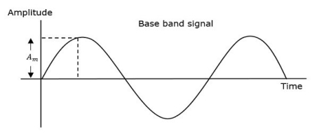
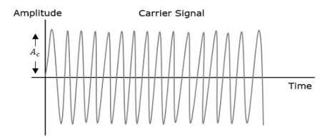
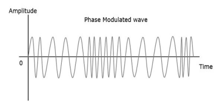
There are infinite points on phase of the modulated wave, where the phase shift in a wave can take place. The amplitude of the modulating signal changes the phase of the carrier signal. If the amplitude is positive, the phase changes in one direction and if the amplitude is negative, the phase changes in the opposite direction.
Mathematical Expression
The equation for phase ϕi in phase modulation is
ϕi = kp m(t)
Where,
Kp: the phase sensitivity
m (t) : the message/ baseband signal
The equation of angle modulated wave is
s(t) = Ac cos (2πfct+ϕi)
Put the value of ϕi in the above equation.
s(t)=Ac cos (2πfct+kpm(t))
Which is the equation of PM wave.
If the baseband signal, m(t)=Am cos (2πfmt), then the equation of PM wave becomes,
s(t)=Ac cos (2πfct+βcos(2πfmt))
Where,
β: modulation index i.e. Δϕ =kpAm
Δϕ: phase deviation
Phase modulation is commonly used in mobile communication systems, while frequency modulation is commonly used for FM broadcasting.
FM signals are complex as compare to AM signals. So, the difference between highest and lowest frequency components is the bandwidth of FM and is given in Hertz (HZ). There are only two sidebands in AM so bandwidth is 2fm.
But in FM it is not so simple, because FM spectrum is complex and have infinite number of sidebands, which is shown in fig below. This fig shows that as modulation index increases, the spectrum expands. Sidebands are given as fc + fm , fc + 2fm, fc + 3fm and so on.
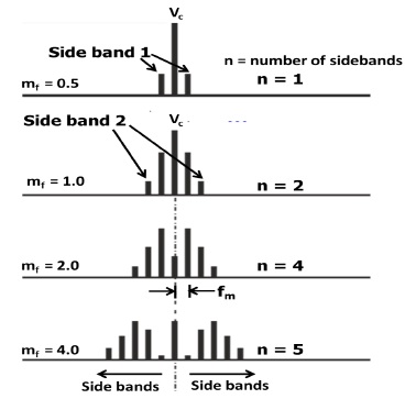
Bandwidth of FM Signal
The first few bands contains the 98% of total power. Therefore only these first few sidebands are considered as significant sidebands.
As the modulation index’s level is increased other sidebands Spectrum also increases. Further increases in modulation index result increasing in level of sidebands.
Carson's Rule for FM bandwidth
The bandwidth of an FM signal is not as easy to calculate as that of an AM signal.
A very useful thumb rule is used to determine the bandwidth of an FM signal for radio broadcast and radio communications systems is known as Carson's Rule. This rule states that 98% of power is contained within a bandwidth which is equal to twice the sum of the deviation frequency and the modulation frequency. Carson's Rule expressed simply as a formula:
BT = 2 (Δf+ fm)
Where
Δf: deviation
BT: total bandwidth (for 98% power)
fm: modulating frequency
Problem 1
A sinusoidal modulating waveform of amplitude 5 V and a frequency of 2 KHz is applied to FM generator, which has a frequency sensitivity of 40 Hz/volt. Calculate the frequency deviation, modulation index, and bandwidth.
Solution
Given, the amplitude of modulating signal, Am=5V.
Frequency of modulating signal, fm=2KHz.
Frequency sensitivity, kf = 40Hz/volt.
We know the formula for Frequency deviation as
Δf = kf Am
Substitute kf and Am values in the above formula.
Δf = 40×5 = 200Hz
Therefore, frequency deviation, Δf is 200Hz.
The formula for modulation index is
β=Δf / fm
Substitute Δf and fm values in the above formula.
β = 2002×1000 = 0.1
Here, the value of modulation index, β is 0.1, which is less than one. Hence, it is Narrow Band FM.
The formula for Bandwidth of Narrow Band FM is the same as that of AM wave.
BW=2fm
Substitute fm value in the above formula.
BW=2×2K=4KHz
Therefore, the bandwidth of Narrow Band FM wave is 4KHz.
Generation of NBFM
We know that the equation of FM is
s(t)=Ac cos (2πfct+2πkf ∫ m(t)dt)
s(t)=Ac cos(2πfct) cos(2πkf ∫m(t)dt) - Acsin(2πfct) sin(2πkf ∫m(t)dt)
For NBFM,
∣ 2πkf ∫m(t)dt ∣ << 1
We know that cosθ≈1 and sinθ≈1 if θ is very small.
By using the above relations, NBFM equation becomes
s (t)=Ac cos (2πfct)− Ac sin (2πfct) 2πkf ∫m(t)dt
The fig given below shows the block diagram of NBFM modulator,
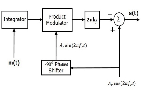
Here, to integrate the baseband signal m(t) the integrator is used.
The −900 phase shifter is used to shift the phase of carrier signal Accos(2πfct) to get Acsin(2πfct).
The product modulator has two inputs ∫m(t)dt and Ac sin (2πfct), which produces an output, which is the product of ∫m(t)dt and Ac sin (2πfct).
The product of two point is further multiplied by 2πkf by placing a block 2πkf in the forward path.
The summer block adds two inputs, which gives the two terns of NBFM equation. Positive and negative signs are given for the carrier signal and the other term at the input of the summer block. Finally, the summer block gives NBFM wave.
Generation of WBFM
There are two methods to generate WBFM
- Direct method
- Indirect method
Direct Method
Name itself indicates that we are generating a WBFM wave directly. In this method, Voltage Controlled Oscillator (VCO) is used to generate WBFM. VCO gives an output signal, whose frequency is proportional to the amplitude of input i.e. modulating signal. Which we have seen in the definition of FM wave. The following figure shows the block diagram of generation of WBFM.

Here, the baseband signal/ modulating signal m(t) is applied as an input to VCO. This VCO produces an output WBFM,
fi α m(t)
fi = fc + kf m(t)
Where,
fi: instantaneous frequency of WBFM wave.
Indirect Method
We are generating a WBFM wave indirectly so called as Indirect Method. In this method firstly we generate NBFM and then by using frequency multipliers WBFM signals are generated. Following figure shows the block diagram of generation of WBFM wave.
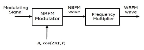
There are two main stages in this method. The first stage is generation of NBFM wave using NBFM modulator. We have seen the block diagram of NBFM modulator in generation of NBFM wave. We know that the modulation index β of NBFM < l. So, to get the modulation index β > 1 of FM wave, we have to choose the frequency multiplier value properly.
Frequency multiplier It is a non-linear device, used to produces an output signal of multiple of input frequency i.e. ‘n’ times the input signal frequency. Where, ‘n’ is the multiplication factor.
When NBFM wave which has modulation index β < 1 is applied as the input to the frequency multiplier, then the frequency multiplier gives an output signal, whose modulation index is ‘n’ times that of β and the frequency also ‘n’ times the frequency of WBFM wave.
Now in this section let us discuss about detection methods which demodulate the FM wave. There are two methods of demodulation.
- Frequency discrimination method
- Phase discrimination method
Frequency Discrimination Method
The equation of FM wave is
s(t)=Ac cos (2πfct+2πkf ∫m(t)dt)
By differentiating above FM wave equation with respect to t we get,
 = −Ac (2πfc+2πkfm(t)) sin(2πfct+2πkf∫m(t)dt)
We can write, − sinθ as sin (θ −1800).
 =Ac (2πfc+2πkf m (t)) sin (2πfct + 2πkf ∫m (t) dt−1800)
 =Ac (2πfc) [1 + (kf /kc) m (t)] sin (2πfct + 2πkf ∫m (t) dt−1800)
In the above equation, the amplitude term looks like the envelope of AM wave and the angle term looks like the angle of FM wave. Here, we require the modulating signal m(t). So, we can recover it from the envelope of AM wave.
The block diagram of FM demodulator using frequency discrimination method is given below.
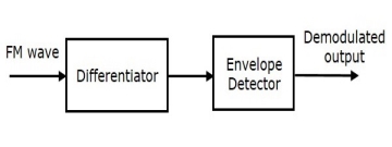
This block diagram consists two blocks. Blocks are 1) The differentiator and 2) The envelope detector. Differentiator converts the FM wave into a combination of AM and FM wave. This means, it is used to convert the frequency variations of FM wave into the corresponding amplitude variations of AM wave. Envelop detector produces the demodulated output of AM wave, which is the original message signal or modulating signal.
Phase Discrimination Method
The block diagram of FM demodulator using phase discrimination method is given below.
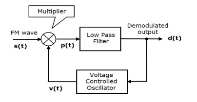
This block diagram consists of three blocks. Blocks are 1) The multiplier, 2) The low pass filter, and 3) The Voltage Controlled Oscillator (VCO). The output of VCO is a signal v(t) and the frequency of v(t) is proportional to the input signal voltage d(t). Initially, when the signal d(t) = 0, adjust the VCO to gives an output signal v(t), having a carrier frequency and −900 phase shift with respect to the carrier signal.
Multiplier multiplies the FM wave s(t) and the VCO output v(t). The multiplier gives an output, having a high frequency component and a low frequency component. The high frequency components are eliminated by Low pass filter and we get the low frequency component as its output.
This low frequency component contains only the term-related phase difference. Hence, we get the modulating signal m(t) from this output of the low pass filter.
FM transmitter takes the audio signal as an input and delivers FM wave to the antenna as an output to be transmitted. The following fig shows the block diagram of FM transmitter.

The working of FM transmitter:
- Pre-amplifier takes the audio signal as input from microphone. This pre-amplifier boosts the level of message signal.
- Amplified signal is passed to HPF, which is pre-emphasis network which removes the noise and improve the SNR i.e. signal to noise ratio.
- This signal is given to the FM modulator as input.
- RF oscillator circuit produces high frequency carrier, which is given to the modulator with baseband/modulating signal.
- Many stages of frequency multiplier are used to increase the operating frequency. Even then, Power of signal is low for transmission. So, the power amplifier is used at the end to increase the power of that signal. Finally this high power FM modulated signal is transmitted through antenna.
The following diagram shows the block diagram of FM receiver,
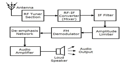
The block diagram of FM receiver and the AM receiver are similar. Amplitude limiter block is included before FM demodulator and De-emphasis network block is included after FM demodulator. All other remaining block are functioning same as that of AM receiver.
We know that, the amplitude and phase of FM wave remains constant in FM modulation. But sometimes, if some noise is added with FM wave in the channel, because of the amplitude of FM wave may vary. Amplitude limiter is used to maintain the amplitude of FM wave as constant. It removes the unwanted noise signal.
The pre-emphasis network is nothing but High pass filter, which is present before FM modulator. This pre-emphasis network is used to improve Signal to Noise Ratio i.e. SNR of high frequency audio signal. The exact reverse process of pre-emphasis is de-emphasis. The de-emphasis network is nothing but Low Pass Filter which is present after FM demodulator. The output of de-emphasis network is passed to the audio amplifier to increase the power level. Final output is the original message or sound signal from loudspeaker.
Reference Books:
- Dr. Sanjay Sharma, “Communication System (Analog and Digital)”, Katson Books.
- Kennedy G, ‘Electronic Communication System’, McGraw Hill, 1987.