Module 4
Codes
The main problem in the signal is Noise or Error. The reliability of system of communication system is disturbed by Noise. To avoid the occurrences of errors, the coding procedure is used for it which is called as Error control coding. These techniques are used for Error Detection and Error Correction.
Linear block codes and Convolution codes are the main types of error correcting codes depending upon the mathematical principles applied to them.
Consider, (n, k) linear block code, in which k bits of the n code bits are always identical to the message sequence to be transmitted. The (n – k) bits in the remaining portion are computed from the message bits in accordance with a prescribed encoding rule that determines the mathematical structure of the code.
Accordingly, these (n – k) bits are referred to as parity-check bits. Block codes in which the message bits are transmitted in unaltered form are called systematic codes. For applications requiring both error detection and error correction, the use of systematic block codes simplifies implementation of the decoder.
Encoding
Let m0, m1, , mk – 1 constitute a block of k arbitrary message bits. Thus, we have 2k distinct message blocks. Let this sequence of message bits be applied to a linear block encoder, producing an n-bit codeword whose elements are denoted by c0, c1, , cn – 1.
Let b0, b1, , bn – k – 1 denote the (n – k) parity-check bits in the codeword. For the code to possess a systematic structure, a codeword is divided into two parts, one of which is occupied by the message bits and the other by the parity-check bits. Clearly, we have the option of sending the message bits of a codeword before the parity-check bits, or vice versa. The former option is illustrated in Figure given below, and its use is assumed in the following.

Fig. Structure of Systematic Codeword
According to the representation of Fig. Given above, the (n – k) leftmost bits of a codeword are identical to the corresponding parity-check bits and the k rightmost bits of the codeword are identical to the corresponding message bits. We may therefore write
ci =  …(1)
…(1)
The (n – k) parity-check bits are linear sums of the k message bits, as shown by the generalized relation.
bi = p0i m0 + p1i m1 ++ pk–1 i mk-1 …(2)
Where the coefficients are defined as,
pij =  …(3)
…(3)
The coefficients pij are chosen in such a way that the rows of the generator matrix are linearly independent and the parity-check equations are unique.
The system equation of (1) and (2) defines the mathematical structure of the (n,k) linear block code. This system of equations may be rewritten in a compact form using matrix notation. To proceed with this reformulation, we respectively define the 1-by-k message vector m, the 1-by-(n – k) parity-check vector b, and the 1-by-n code vector c as follows
m = [m0, m1, …, mk-1] ---(4)
b = [b0, b1, …, bn-k-1] ---(5)
c = [c0, c1, …, cn-1] ---(6)
All the three vectors are row vectors. We may thus rewrite the set of simultaneous equations defining the parity check-bits in the compact matrix form,
b = mP …(7)
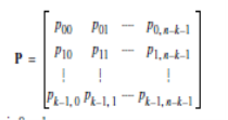
The P in (7) is the k by (n – k) coefficient matrix defined by,
 …(8)
…(8)
Where the element pij is 0 or 1
From the equation (4)–(6), we see that c may be expressed as a partitioned row vector in terms of the vectors m and b as follows,
c = [b | m] … (9)
Putting (7) into (9) and factoring out the common message vector m, we get,
c = m [P | Ik] … (10)
Where Ik is the k-by-k identity matrix
 … (11)
The k-by-n generator matrix
G = [P | Ik] --- (12)
The generator matrix G of equation (12) is said to be in the canonical form, in that its k rows are linearly independent. Using the definition of the generator matrix G, we can simplify equation (10) as,
c = mG --- (13)
The full set of codewords is generated in accordance with equation (13) by passing the message vector m range through the set of all 2k binary k-tuples (1-by-k vectors). Moreover, the sum of any two codewords in the code is another codeword. This basic property of linear block codes is called closure.
To prove its validity, consider a pair of code vectors ci and cj corresponding to a pair of message vectors mi and mj, respectively. Using equation (13), we may express the sum of ci and cj as
ci + cj = miG + mjG
= (mi + mj ) G
The modulo-2 sum of mi and mj represents a new message vector. Correspondingly, the modulo-2 sum of ci and cj represents a new code vector.
There is another way of expressing the relationship between the message bits and parity-check bits of a linear block code. Let H denote an (n – k)-by-n matrix, defined as
H = [In-k | PT] --- (14)
Where PT is an (n–k)-by-k matrix, representing the transpose of the coefficient matrix P, and In–k is the (n–k)-by-(n–k) identity matrix. Accordingly, we can perform the following multiplication of partitioned matrices

Where we have used the fact that multiplication of a rectangular matrix by an identity matrix of compatible dimensions leaves the matrix unchanged. In modulo-2 arithmetic, the matrix sum PT + PT is 0. Therefore we have,
HGT = 0 … (15)
Similarly, we have GHT = 0, where 0 is a new null matrix. Post multiplying both sides of equation (13) by HT, the transpose of H, and then using equation (15), we get the product,
CHT = mGHT
= 0
The matrix H is called the parity-check matrix of the code and the equations specified by equation (16) are called parity-check equations.
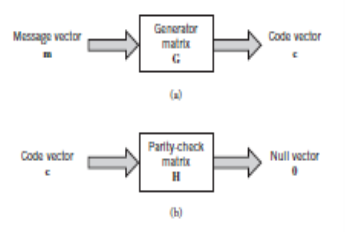
The generator equation (13) and the parity-check detector equation (16) are basic to the description and operation of a linear block code. These two equations are depicted in the form of block diagrams in Figure a and b, respectively.

Fig. Block diagram representation of the generator equation and parity check equation
Sending the code vector cover a noisy binary channel. We express the vector r as the sum of the original code vector c and a new vector e, as shown by
r = c + e ... (17)
The vector e is called the error vector or error pattern. The ith element of e equals 0 if the corresponding element of r is the same as that of c. On the other hand, the ith element of e equals 1 if the corresponding element of r is different from that of c, in which case an error is said to have occurred in the ith location. That is, for i = 1, 2,, n, we have,
ei =  … (18)
The receiver has the task of decoding the code vector c from the received vector r. The algorithm commonly used to perform this decoding operation starts with the computation of a 1-by-(n – k) vector called the error-syndrome vector or simply the syndrome. The importance of the syndrome lies in the fact that it depends only upon the error pattern.
Given a 1-by-n received vector r, the corresponding syndrome is formally defined as
s = rHT --- (19)
Syndrome Decoding
A syndrome-based decoding scheme for linear block codes is explained below. Let c1, c2, …, c2k denote the 2k code vectors of an (n, k) linear block code.
Let r denote the received vector, which may have one of 2n possible values. The receiver has the task of partitioning the 2n possible received vectors into 2k disjoint subsets D1, D2, …, D2k in such a way that the ith subset Di corresponds to code vector ci for 1 <= i <= 2k .
The received vector r is decoded into ci if it is in the ith subset. For the decoding to be correct, r must be in the subset that belongs to the code vector ci that was actually sent.
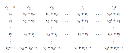
The 2k subsets described herein constitute a standard array of the linear block code. To construct it, we exploit the linear structure of the code by proceeding as follows
- The 2k code vectors are placed in a row with the all-zero code vector c1 as the leftmost element.
- An error pattern e2 is picked and placed under c1, and a second row is formed by adding e2 to each of the remaining code vectors in the first row; it is important that the error pattern chosen as the first element in a row has not previously appeared in the standard array.
- Step 2 is repeated until all the possible error patterns have been accounted for.

Fig. Standard array for an (n,k) block code.
Figure above gives the structure of the standard array. The 2k columns of this array represent the disjoint subsets D1, D2, …, D2k . The 2n–k rows of the array represent the cosets of the code, and their first elements e2, …, e2n-k are called coset leaders.
For a given channel, the probability of decoding error is minimized when the most likely error patterns (i.e., those with the largest probability of occurrence) are chosen as the coset leaders. In the case of a binary symmetric channel, the smaller we make the Hamming weight of an error pattern, the more likely it is for an error to occur. Accordingly, the standard array should be constructed with each coset leader having the minimum Hamming weight in its coset.
A decoding procedure for linear block codes:
- For the received vector r, compute the syndrome s = rHT.
- Within the coset characterized by the syndrome s, identify the coset leader (i.e., the error pattern with the largest probability of occurrence); call it e0.
- Compute the code vector c = r + e0 as the decoded version of the received vector r.
Cyclic codes form a subclass of linear block codes. Indeed, many of the important linear block codes discovered to date are either cyclic codes or closely related to cyclic codes. An advantage of cyclic codes over most other types of codes is that they are easy to encode. Furthermore, cyclic codes possess a well-defined mathematical structure, which has led to the development of very efficient decoding schemes for them.
Encoding of Cyclic Codes
The encoding procedure for an (n,k) cyclic code in systematic form involves three steps:
- Multiplication of the message polynomial m(X) by Xn–k.
- Division of Xn–km(X) by the generator polynomial g(X) to obtain the remainder b(X), and
- Addition of b(X) to Xn–km(X) to form the desired code polynomial.
The boxes in Figure given below represent flip-flops, or unit-delay elements. The flip-flop is a device that resides in one of two possible states denoted by 0 and 1. An external clock (not shown in Figure) controls the operation of all the flip-flops. Every time the clock ticks, the contents of the flip-flops (initially set to the state 0) are shifted out in the direction of the arrows.
In addition to the flip-flops, the encoder of Figure includes a second set of logic elements, namely adders, which compute the modulo-2 sums of their respective inputs. Finally, the multipliers multiply their respective inputs by the associated coefficients.
If the coefficient gi = 1, the multiplier is just a direct “connection.” If, on the other hand, the coefficient gi = 0, the multiplier is “no connection.”

Fig. Encoder for an (n,k) cyclic code
The operation of the encoder shown in Figure proceeds as follows
- The gate is switched on. Hence, the k message bits are shifted into the channel. As soon as the k message bits have entered the shift register, the resulting bits in the register form the parity-check bits. (Recall that the parity-check bits are the same as the coefficients of the remainder b(X).)
- The gate is switched off, thereby breaking the feedback connections.
- The contents of the shift register are read out into the channel.
Suppose the code word (c0, c1, …, cn-1) is transmitted over a noisy channel, resulting in the received word r0, r1, …,rn-1. The first step in the decoding of a linear block code is to calculate the syndrome for the received word. If the syndrome is zero, there are no transmission errors in the received word. If the syndrome is nonzero, the received word contains transmission errors that require correction.

Fig. Syndrome Calculator for (n,k) cyclic code
In the case of a cyclic code in systematic form, the syndrome can be calculated easily. Let the received vector be represented by a polynomial of degree or less, as shown by

Let q(X) denote the quotient and s(X) denote the remainder, which are the results of dividing r(X) by the generator polynomial g(X). Therefore express r(X) as follows,

The remainder s(X) is a polynomial of degree n-k-1 or less, which is the result of interest. It is called the syndrome polynomial because its coefficients make up the (n-k)-by-1 syndrome s.
Figure above shows a syndrome calculator that is identical to the encoder figure except for the fact that the received bits are fed into the stages of the feedback shift register from the left. As soon as all the received bits have been shifted into the shift register, its contents define the syndromes.
In block coding, the encoder accepts a k-bit message block and generates an n-bit codeword, which contains n – k parity-check bits. Thus, codewords are produced on a block-by-block basis. Provision must be made in the encoder to buffer an entire message block before generating the associated codeword.
There are applications where the message bits come in serially rather than in large blocks, in which case the use of a buffer may be undesirable. In such situations, the use of convolutional coding may be the preferred method.
A convolutional coder generates redundant bits by using modulo-2 convolutions; hence the name convolutional codes.
Encoder of Convolution Codes
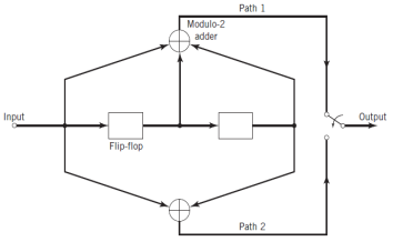
The encoder of a binary convolutional code with rate 1n, measured in bits per symbol, may be viewed as a finite-state machine that consists of an M-stage shift register with prescribed connections to n modulo-2 adders and a multiplexer that serializes the outputs of the adders.
A sequence of message bits produces a coded output sequence of length n(L + M) bits, where L is the length of the message sequence. The code rate is therefore given by,

Typically, we have L M, in which case the code rate is approximately defined by,

The constraint length which is an important characteristic of a convolutional code is define as follows:
The constraint length of a convolutional code, expressed in terms of message bits, is the number of shifts over which a single incoming message bit can influence the encoder output.
In an encoder with an M-stage shift register, the memory of the encoder equals M message bits. Correspondingly, the constraint length, equals M + 1 shifts that are required for a message bit to enter the shift register and finally come out.

Fig. Convolution Encoder
Fig shows a convolutional encoder with the number of message bits n = 2 and constraint length v = 3. In this example, the code rate of the encoder is 12. The encoder operates on the incoming message sequence, one bit at a time, through a convolution process; it is therefore said to be a nonsystematic code.
Each path connecting the output to the input of a convolutional encoder may be characterized in terms of its impulse response, defined as follows
The impulse response of a particular path in the convolutional encoder is the response of that path in the encoder to symbol 1 applied to its input, with each flip-flop in the encoder set initially to the zero state.
Similarly, we may characterize each path in terms of a generator polynomial, defined as the unit-delay transform of the impulse response. To be specific, let the generator sequence (g0i,g1i, g2i , ,gMi ) denote the impulse response of the ith path, where the coefficients g0i,g1i, g2i , ,gMi equal symbol 0 or 1. The generator polynomial of the ith path is defined by

Where D denotes the unit-delay variable. The complete convolutional encoder is described by the set of generator polynomials {g(i)(D) }iM = 1.
Reference Books:
- Simon Haykins, ‘Communication Systems’, John Wiley, 3rd Edition, 1995.
- Kennedy G, ‘Electronic Communication System’, McGraw Hill, 1987.