Unit 6
Introduction to Optimal Control and Nonlinear Control
A control system is optimum when the selected performance index is minimized. The optimum value of the system parameter depends directly on the optimality.Many further studies suggest that for various order system to achieve zero steady state step and ramp error systems and minimize ITAE. The transfer function for zero steady state step error system is given as
T(s) =  =
=  (1)
(1)
 =
= 
s+ n
n
s2+1.4 n+
n+ n2
n2
s3+1.75 ns2+2.15
 n2s+
n2s+ n3
n3
s4+2.1 ns3+3.4
 n2s2+2.7
 n3s+
n3s+ n4
n4
s5+2.8 ns4+5.0
 n2s3+5.5
 n3s2+3.4
 n4s+
n4s+ n5
n5
The above table shows the optimal form of closed loop transfer function based on ITAE criterion. In (1) the coefficients are varied until the ITAE value becomes minimal and these values are listed in the table above. These standard forms make it easy to synthesize an optimum dynamic response.
The closed loop transfer function for zero steady state ramp error systems is
T(s) =  =
= 
 =
=
s2+3.2 n+
n+ n2
n2
s3+1.75 ns2+3.25
 n2s+
n2s+ n3
n3
s4+2.41 ns3+4.93
 n2s2+5.14
 n3s+
n3s+ n4
n4
s5+2.19 ns4+6.50
 n2s3+6.30
 n3s2+5.24
 n4s+
n4s+ n5
n5
s6+6.12 ns4+13.24
 n2s4+17.16
 n3s3+14.14
 n4s2+6.76
 n5s+
n5s+ n5
n5
The above table shows the optimum forms of closed loop transfer function based on ITAE criterion for steady state ramp error systems.
In the state regulator problem, the main aim is to make the components of the output vector small. If controlled process is observable than the output regulator problem can be reduced to state regulator problem.
Output Regulator Problem:
Let the state equation of any plant be  =Ax(t)+Bu(t)
With initial conditions as x(0) = x0
y(t) = Cx(t)
We need to find the control law u*(t) such that the quadratic performance index is minimized.
J=  yT(tf)Hy(tf) +
R= positive constant
H,Q = Positive definite constants
The above equation shows that we need to keep the output y(t) near to zero. Substitute y(t) = Cx(t) in above equation.
J=  xT(tf)CTHCx(tf) +
The optimal control system is given by
u*(t) = -R-1BTP(t)x(t) = K(t)x(t)
Where P(t) = solution of Reccati equation given as
 +CTQC-P(t)BR-1BTP(t)+P(t)A+ATP(t)=0
The boundary conditions are P(tf)=CTHC
The output tracking problem:
Considering an observable process defined by equation
 =Ax(t)+Bu(t) for x(0) =x0
y(t) = Cx(t)
Now the main aim is to keep output y(t) close to desired output r(t). The error is defined as
e(t) = y(t)-r(t)
We must minimise the performance index.
J=  eT(tf)He(tf) +
This can be reduced to output regulator problem only if r(t) is considered which is generated by some initial conditions z(0) in the system.
 =Az(t)
r(t) = Cz(t)
Let w=x-z
 = Aw+Bu
e=Cw
By applying results of output regulator problem, we get the optimal control for the tracking problem.
u*(t) = -R-1BTP(t)w = K(t)[x-z]
P(t) =solution of Riccati equation.
 +CTQC-P(t)BR-1BTP(t)+P(t)A+ATP(t)=0
The boundary conditions are P(tf)=CTHC
Basic definition of a non-linear system is that the system which doesnot hold principle of superposition. In fact, the nonlinear system response may be highly sensitive to input amplitude. The stability of such systems is very much dependent on input and initial state. The common physical nonlinearities are:
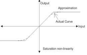
i) Saturation: It is the most common nonlinearity of all. The systems when driven by sufficiently large signals, exhibit the phenomenon of saturation due to limitation of physical capabilities of their components. The output of the system is proportional to input for some region.
Ii) Friction: This force exists when the mechanical surface come in the sliding contact. The predominant frictional force is called as viscous friction. This friction is proportional to relative velocity of sliding surface. Viscous friction is linear in nature. The other two nonlinear frictions are coulomb friction which is a constant retarding force and stiction friction which is the force required to initiate the motion.
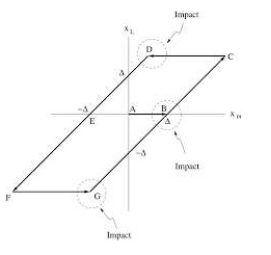
Iii) Backlash: This is nothing else but hysteresis in mechanical transmission such as gear train and linkages. It is between the teeth of the drive gear and those of driven gear. When the back lash is traversed, no torque is developed in shaft. But when the contact is achieved the impact can destroy the gear and causes high frequency noise.
Iv) Dead Zone: In this the system will not respond to the given input until the input reaches a particular level.
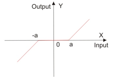
This error reduces accuracy of system and degrades its performance. This nonlinearity can be seen in diodes, actuators.
v) Relay: It can introduce a large power amplification and is deliberately introduced in the system. A relay-controlled system can be switched abruptly between several discrete states such as off, full forward and full reverse.
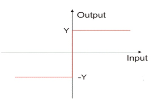
Practical relay has definite amount of dead zone. To close relay large amount of current is needed. The characteristics hence exhibits hysteresis.
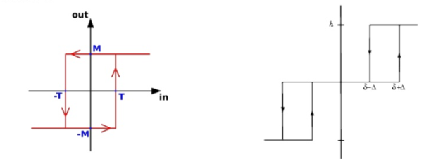
They are used in power system, temperature control system, aircraft, and missile control system.
Basic concept:
Let us consider a spring mass damper system described as
M +f
+f +Kx =0
The above equation can also be written as
 = 2
= 2 ωn
ωn +ωn2x=0
x= displacement
 = velocity
x1= x
x2= 
 = x2
= x2
 = -ωn2x1-2
 ωn
ωn
It is difficult to obtain the solution for the differential equation when the system is nonlinear. The above equations now become
 = x2
= x2
 = -
= - x2-
x2- x1-
x1- x13
x13
The graphical method provides the same information as the time response curves and is called as phase-plane method. The coordinate plane with axes x1=x and x2= is called phase-plane. The phase-plane method is easily constructable graphical picture of the complete system response.
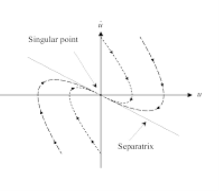
Fig: Phase portrait of critically damped system
Singular points: For a general time-invariant system described by state equation  = f(x,u)
When u is constant  = F(x)
The system having such state equations are called as autonomous system. For such systems points in the phase space at which the derivatives of all the state variables are zero. These points are called as singular points. If the system is placed at such a point it will continue to lie there if left undisturbed. The linearized model of system is given as  = Ax
= Ax
For these systems the equilibrium states are given those states xe satisfying Axe=0.
xe=0 is the solution of above equation. xe is a singular point. The new phase variable  = x-xe. The system equation can now be represented as
 =F(
=F( )
)
The canonical form of equation  = Ax is represented as
 =
= 
 ,
,  are eigen values of A and are distinct.
Nodal Point: when  ,
,  are both real and negative their trajectories converge to origin which is called a nodal point. When
  ,
,  are both real and positive the result is an unstable nodal point.
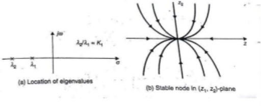
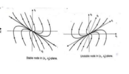
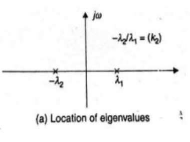
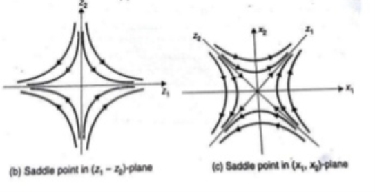
Saddle point: When  ,
,  are both real, equal, and negative the trajectories are shown below. The saddle point here is unstable as one eigen value being negative.
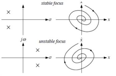
Focus Point: when  ,
,  =
=  . The origin is the focus point and is stable for negative real parts of eigen values and unstable for positive real parts of eigen values.
Centre or Vortex Point: The phase portrait has closed path trajectories as shown below and the centre is called centre.