UNIT 3
DC-DC BUCK CONVERTER
Chopper is a basically static power electronics device which converts fixed DC voltage/power to variable DC voltage or power. It is nothing but a high speed switch which connects and disconnects the load from source at a high rate to get variable or chopped voltage at the output.
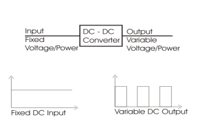
Fig: DC to DC converter
The power semiconductor devices used for chopper circuit can be power BJT, power MOSFET, GTO or forced commutated SCRs. These devices are represented by a switch. When switch is OFF, no current flows. When switch is ON, current flows in the direction of arrow only as shown in fig below. For simplicity the voltage drop across these devices is neglected.
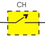
Fig: Chopper as switch
A chopper is a dc equivalent to an ac transformer having variable turns ratio. Therefore chopper can be used as step down and step up the fixed dc input voltage. The step down chopper is most widely used chopper in applications.
Operation of Chopper circuit

Fig (a) Elementary chopper circuit (b) output voltage and current waveform
As chopper is high speed ON/OFF semiconductor switch, it connects and disconnects source to load at a fast speed. During TON period, chopper is ON and load voltage V0 is equal to source voltage Vs.
During TOFF period, chopper is OFF, load current flows through freewheeling diode FD. So the load terminals are short and load voltage V0 is zero as shown in waveform. In this way chopped dc voltage is produced at load terminals.
Concepts of duty cycle and average voltage
Duty cycle of chopper is defined as the ratio of ON time to the total time period. It is denoted by symbol α. Total time period is the sum of ON and OFF time.
Duty Cycle α = TON / (TON+TOFF)
Assuming (TON+TOFF) = T, duty cycle is given as below.
Duty Cycle, α = (TON / T)
Where,
The time for which chopper connects the load from source is called ON time i.e. TON.
And the time for which load is disconnects from source is called OFF time i.e. TOFF.
Calculation of Output Voltage:
The average output voltage of chopper may be find from the output voltage waveform. It is clear from the o/p voltage waveform that, voltage V0 is available only for TON time period in the total time (TON+TOFF). Therefore, average output voltage V0 may be calculated as shown below.
V0 = TON Vs / (TON+TOFF)
But, TON / (TON+TOFF) = α
Hence,
V0 = αVs
Thus, the output voltage may be controlled by controlling the duty cycle. From the expression of output voltage, it is also clear that, the output voltage is independent of the load current.
The Step down Chopper or Buck converter reduces the input DC voltage to a specified DC output voltage. A typical Buck converter is shown below. The input voltage source is connected to a controllable solid state device which operates as a switch.
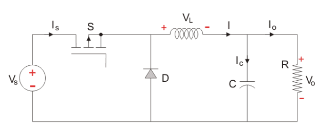
Fig: buck converter
The second switch used is a diode. The switch and the diode are connected to a low-pass LC filter which is appropriately designed to reduce the current and voltage ripples. The load is a purely resistive load.
The input voltage is constant and the current through load is also constant. The load can be seen as current source.
The controlled switch is turned on and off by using Pulse Width Modulation (PWM). PWM can be time based or frequency based.
Analysis and waveforms at steady state, duty ratio control of output voltage
Time based Modulation is mostly used for DC-DC converters. The frequency remains constant in this type of PWM modulation.
The Buck converter has two modes of operation. The first mode is when the switch is on and conducting.
Mode I: Continuous mode(Switch is ON, Diode is OFF)
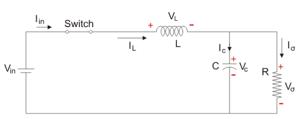
Fig: buck converter in continuous mode
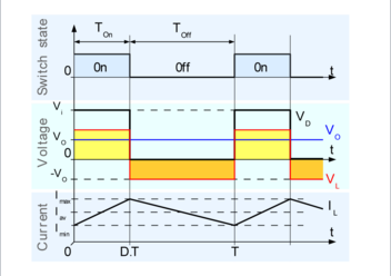
Fig: waveform of Buck converter in continuous mode
Buck converter operates in continuous mode if the current through the inductor (IL) never falls to zero during the commutation cycle.
- When the switch pictured above is closed , the voltage across the inductor is (VL=Vi-V0)
- The current through the inductor rises linearly (in approximation, so long as the voltage drop is almost constant). As the diode is reverse-biased by the voltage source V, no current flows through it.
The voltage across the capacitance in steady state is equal to the output voltage.
Now the switch is on for a time TON and is off for a time TOFF. The time period, T, is defined as  and the switching frequency,
 And the duty cycle D, as

Let us analyse the Buck converter in steady state operation for this mode using KVL.
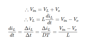
Since the switch is closed for a time TON = DT we can say that Δt = DT.

Mode II: Discontinues Mode
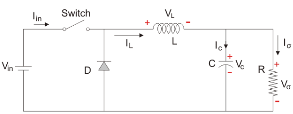
Fig: Buck converter in Discontinues Mode
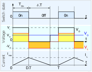
Fig: waveform of Buck converter in discontinuous mode
Here, the energy stored in the inductor is released and is ultimately dissipated in the load resistance, and this helps to maintain the flow of current through the load. But for analysis we will use the original conventions to analyse the circuit using KVL.
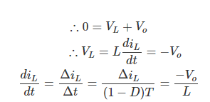
Since the switch is open for a time  we can say that Δt = (1- D)T

It is already established that the net change of the inductor current over anyone complete cycle is zero.
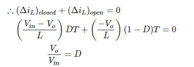
Important Point to be remember while designing buck converter
- The inductor current is continuous and, this is made possible by selecting an appropriate value of L.
- The inductor current in steady state rises from a value with a positive slope to a maximum value during the ON state and then drops back down to the initial value witha negative slope. Therefore the net change of the inductor current over anyone complete cycle is zero.