Unit 4
DC-DC boost converter
Sometimes we come across situations where we need a slightly higher voltage than our power supplies can provide. For examplewe need 12 volts at output but have only a 9 volt battery at input side. Or maybe we have a 3.3V supply when our chip needs 5V. In such application Boost converter or Step-Up chopper is plays a vital role.
A boost converter (step-up converter) is a DC-to-DC power converter that steps up voltage (while stepping down current) from its input (supply) to its output (load).
The key principle that drives the boost converter is the tendency of an inductor to resist changes in current by either increasing or decreasing the energy stored in the inductor magnetic field. In a boost converter, the output voltage is always higher than the input voltage.

Fig: Boost converter
If the switching is fast enough, the inductor will not discharge fully in between charging stages, and the load voltage greater than that of the input source.
Also while the switch is opened, the capacitor in parallel with the load is charged to this combined voltage. When the switch is then closed and the right hand side is shorted out from the left hand side, the capacitor is therefore able to provide the voltage and energy to the load.
During this time, the blocking diode prevents the capacitor from discharging through the switch. The switch must of course be opened again fast enough to prevent the capacitor from discharging too much.
The basic principle of a Boost converter consists of following 2 states
- In the On-state, the switch S is closed, resulting in an increase in the inductor current;
- In the Off-state, the switch is open and the only path offered to inductor current is through the fly back diode D, the capacitor C and the load R. This results in transferring the energy accumulated during the On-state into the capacitor.
Continuous mode
When a boost converter operates in continuous mode, the current through the inductor (IL) never falls to zero. Following figure shows the typical waveforms of inductor current and voltage in a converter operating in this mode.
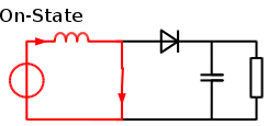
Fig: on stateboost converter in continuous mode

Fig: Boost converter in continuous mode
In the steady state, theaverage voltage across the inductor must be zero so that after each cycle the inductor returns the same state, because voltage across the inductor is proportional to rate of change of current through it.
The output voltage can be calculated as follows,
In the case of an ideal converter (i.e. using components with an ideal behaviour) operating in steady conditions:
During the On-state, the switch S is closed, which makes the input voltage (Vi) appear across the inductor, which causes a change in current (IL) flowing through the inductor during a time period (t) by the formula:
 where L is value of inductor
At the end of ON state, the inductor current (IL) is,
 where D is the duty cycle
It represents the fraction of the commutation period T during which the switch is On. Therefore, D ranges between 0 (S is never on) and 1 (S is always on).
In steady state condition, the energy stored in the inductor is given by:

So, the inductor current has to be the same at the start and end of the commutation cycle. This means the overall change in the current (the sum of the changes) is zero:

Substituting ∆ILon and ∆ILoFF by their expressions yields:

Rearranging the equation,

Or in terms of Duty cycle,

Discontinuous Mode
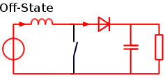
Fig: OFF state boost converter

Fig: boost converter in discontinuous mode
We know that when S is ON, currentthrough the load would increase from 0 to Imaxas shown in waveform. When S is OFF current fall from Imaxto 0.
By applying KCL, gives,
VL-V0+Vs=0
VL=V0-Vs
At steady state condition, the energy input to inductor from the source, during TON is,

During the TOFF time when S is Off, the energy realised by inductor to load is

Considering lossless system, equating two energy equations we can write,
 where D=α= duty cycle
It is seen from above equation, that average voltage across the load can be stepped up by varying the duty cycle. If S is always OFF, then α=0 and V0-=Vs. If S is always ON, then α=1 and V0-=∞ (Infinity). By turning On and OFF S/chopper, α makes variable and the required step-up average output voltage, more than source voltage is obtained.
Ex.1 For the basic dc to dc converter shown in fig , express the following variables as a function of Vs, R and duty cycle D in case of resistive load:
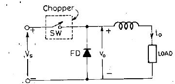
(a) Average output voltage and current
(b) Output current at instant of commutation
(c) Average and rms freewheeling diode current
(d) rms value of output voltage
(e) rms value thyristor current
(f) effective output of resistance of chopper circuit
Ans: 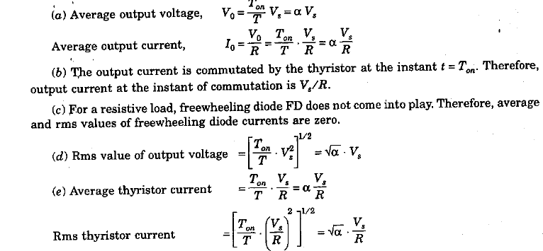

Ex. 2 For chopper shown in fig, dc source voltage is 230V, load resistance is 10 Ω. Take a voltage drop of 2V across chopper when it is on. For a duty cycle of 0.4, calculate
(a) average and rms values of output voltage and
(b) chopper efficiency
(c) 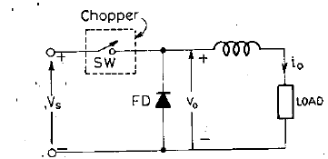
Ans: 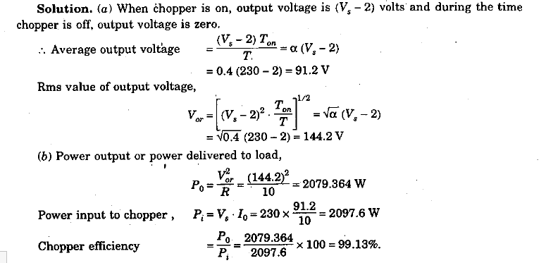
Ex 3. A step up chopper has input voltage of 220V and output voltage of 660V. If the non-conducting time of thyristor chopper is 100 µs, compute the pulse width of output voltage.
If case pulse width is halved for constant frequency operation, find the new output voltage.
Ans: we know that, V0=Vs 1/1-α
