Module 7
AC to AC Converter
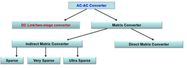
In power conversion, when AC is converted to low voltage DC, or AC from one frequency to another, the AC is usually rectified and smoothed. Once this is accomplished, the power is then routed to an inverter to obtain the final output. The DC that is fed into the inverter is called the DC link.
A matrix converter is defined as a converter with a single stage of conversion. It utilizes bidirectional controlled switch to achieve automatic conversion of power from AC to AC. It provides an alternative to PWM voltage rectifier double-sided.
Indirect matrix converter:
The basic concept of the IMC is to separate the AC/AC conversion into two stages such as rectifier and inverter stages with no DC link capacitor.
The rectifier stage is composed of six bi-directional switches built with twelve unidirectional switches, while the inverter stage has six unidirectional switches. As a result, independent switching modulation strategies can be used for each stage. The purpose of the rectifier is generating the sinusoidal input currents as well as maintaining a constant local-averaged dc output voltage in the DC-link, by modulating the two line-to-line input voltages.
The Output voltages with variable frequency and variable amplitude can be obtained through the conventional space vector PWM modulation of the inverter stage, using the constant DC voltage obtained from the rectifier stage.
Direct matrix
It consists of nine bidirectional switches that connect each output phase to each input phase. Bidirectional switches are configured from back to back connected unidirectional switches.
A bidirectional switch is capable of conducting currents and blocking voltages of both polarities, depending on control signal which is realized by the combination of conventional unidirectional semiconductor devices.
Step-up cyclo-converter is a single phase to single phase device which converts input AC power at one frequency to output power at a different frequency.
The output frequency is more than the input frequency for this cyclo-converter.
Single phase to single phase means that both the input power and output power are single phase.
There are two circuit configurations
Mid-point Type
Bridge Type.
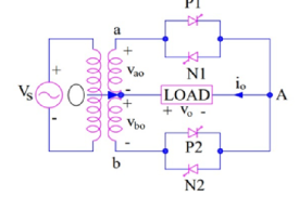
The circuit consists of a single- phase transformer with mid tap on the secondary winding and four thyristors. Two of these thyristors P1 & P2 are for positive group. Here positive group means when either P1 or P2 conducts, the load voltage is positive.
The other two thyristors N1 & N2 are for negative group. Load is connected between secondary winding mid-point O and terminal A. The load is resistive and assumes positive direction for voltage and current as shown in figure.
During the positive half cycle of input supply voltage, positive group thyristors P1 & N2 are forward biased for ωt = 0 to ωt = π.
SCR P1 is fired and turns ON at ωt = 0 such that load voltage is positive with terminal A positive and O negative.
The load voltage, thus, follows the positive envelop of the input supply voltage.
At time instant ωt = ωt1, the conducting thyristor P1 is force commutated and the forward biased thyristor N2 is fired to turn it ON.
During the period N2 conducts, the load voltage is negative because O is positive & A is negative this time.
The load or output voltage traces the negative envelop of the supply voltage.
This is shown in figure below.
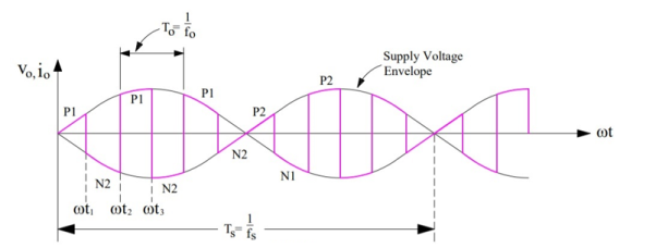
At ωt = ωt2, N2 is force commutated and P1 is turned ON. The load voltage is now positive and follows the positive envelop of the supply voltage.
At ωt = π, terminal “b” is positive with respect to terminal “a”; both SCRs P2 & N1 are therefore forward biased from ωt = π to ωt = 2π.
AT ωt = π, N2 is force commutated and forward biased SCR P2 is turned ON. The load voltage is positive and follows the positive envelop of supply voltage.
If the supply frequency is fs and output frequency is fo, P2 will be force commutated at ωt = (1/2fs) + (1/2fo).
When P2 is force commutated, forward biased SCR N1 is turned ON. This time, the load voltage is negative and follows the negative envelop of the supply input.
In this way SCRs P1, N2 for the first half cycle, P2, N1 in the second half cycle are switched alternately between positive and negative envelops at high frequency. This results in output frequency fo more than the input supply frequency fs.
Hence in figure-2 there is a total of 6 cycles of output in one cycle of input supply. This means that frequency of output voltage is 6 times of input frequency i.e.
fo = 6fs.
Step Down:
Operation:
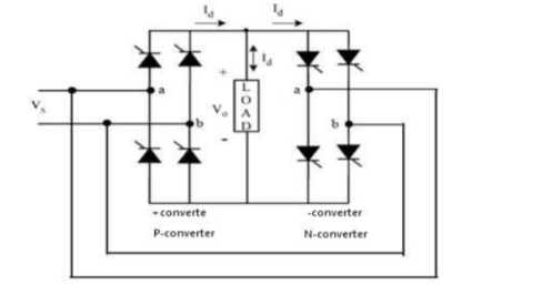
It consists of two full-wave, fully controlled bridge thyristors, where each bridge has 4 thyristors, and each bridge is connected in opposite direction (back to back) such that both positive and negative voltages can be obtained as shown in figure below.
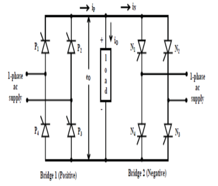
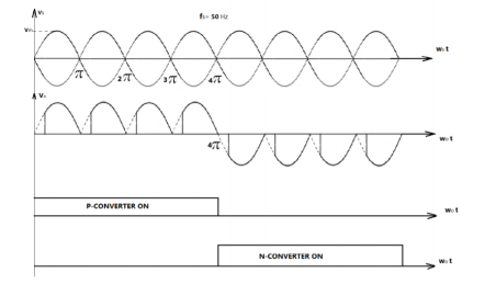
During positive half cycle of the input voltage, positive converter (bridge-1) is turned ON and it supplies the load current.
During negative half cycle of the input, negative bridge is turned ON and it supplies load current.
Both converters should not conduct together that cause short circuit at the input. In order to avoid triggering to thyristors of bridge-2 is inhibited during positive half cycle of load current, while triggering is applied to the thyristors of bridge 1 at their gates.
During negative half cycle of load current, triggering to positive bridge is inhibited while applying triggering to negative bridge.
By controlling the switching period of thyristors, time periods of both positive and negative half cycles are changed and hence the frequency. This frequency of fundamental output voltage can be easily reduced in steps, i.e., 1/2, 1/3, 1/4 and so on.
The output waveforms of a cyclo-converter are shown where it produces one-fourth of the input frequency. Here, for the first two cycles, the positive converter operates and supplies current to the load.
It rectifies the input voltage and produce unidirectional output voltage as we can observe four positive half cycles in the figure.
And during next two cycles, the negative converter operates and supplies load current.
Single phase to single phase cyclo-converter with resistive load
This converter consists of back to back connection of two full-wave bridge rectifier circuits as shown in figure and shows the operate waveforms of this cyclo-converter with resistive load.
If the input voltage is
Vs = Vm sin ws t
Then the rms output voltage is given by
Vo = { 8/8π  Vs sin wst ) 2 dwt } ½
= 16 Vs 2 / 16 π  cos 2 wst ) dwt
= Vs [ 1/π ( π – αp + sin 2αp/2 )] ½
When p-converter operating alone, the output voltage is positive half-cycles, with average output voltage of

Vd1 = 2Vm / π cos α step down converter
The output frequency is fo = 1/To = ¼ fs . Also, when N-converter operating alone the output voltage is negative with average value Vd2 = -Vd1
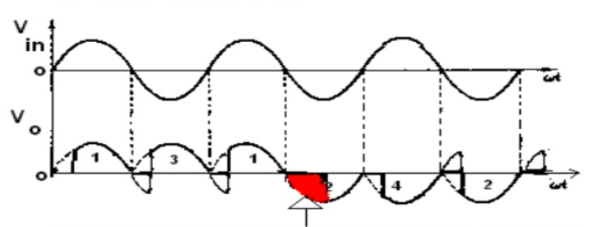
For inductive load the negative portion of half cycle will appear in positive half cycle of the load voltage waveform.
The waveform are
There are two kinds of three-phase to single-phase (3f-1f) cyclo-converters:
3f-1f half-wave cycloconverter (Fig.a) and
3f-1f bridge cycloconverter (Fig. b).
The 3f-1f cycloconverter applies rectified voltage to the load. Both positive and negative converters can generate voltages at either polarity, but the positive converter can only supply positive current and the negative converter can only supply negative current.
Thus, the cycloconverter can operate in four quadrants: (+v, +i) and (-v, -i) rectification modes and (+v, -i) and (-v, +i) inversion modes.
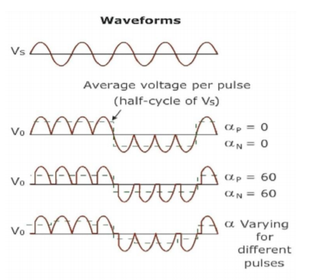
The modulation of the output voltage and the fundamental output voltage
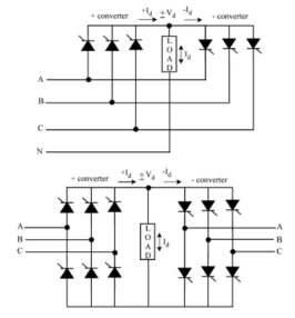
Figure (a)
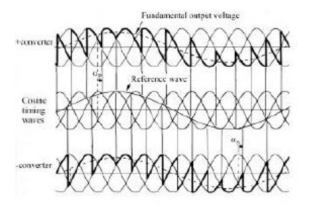
Figure (b)
The polarity of the current determines if the positive or negative converter should be supplying power to the load.
Conventionally, the firing angle for the positive converter is named aP, and that of the negative converter is named aN.
When the polarity of the current changes, the converter previously supplying the current is disabled and the other one is enabled. The load always requires the fundamental voltage to be continuous.
Therefore, during the current polarity reversal, the average voltage supplied by both converters should be equal. Otherwise, switching from one converter to the other one would cause an undesirable voltage jump.
To prevent this problem, the converters are always forced to produce the same average voltage. Thus, the following condition for the firing angles should be met
αP + αN = π
The fundamental output voltage is given as
Vo1 (t) = √2 Vo sin wot
Where Vo is the rms value of the fundamental voltage.
At a time to the output fundamental voltage is
Vo1(to) = √ 2 Vo sin wo to
The positive converter can supply this voltage if αp satisfies the following condition
Vo1(to) = √ 2 Vo sin wo to = Vdc cos αp
Where Vdc = √ 2 Vo p/π sin π/p (p=3 half wave converter and 6 for bridge converter.
From the α condition
V01 = Vdc cos αp = -Vdc sin αN.
Half wave:
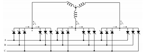
If the outputs of 3 phase to single phase converters are of the same kind they are connected in wye or delta and if the output voltages are 2p/3 radians phase shifted from each other, the resulting converter is a three-phase to three-phase (3f-3f) cycloconverter.
The resulting cyclo-converters are shown in Figs.a and b with wye connections. If the three converters connected are half-wave converters, then the new converter is called a 3f-3f half-wave cycloconverter.
If instead, bridge converters are used, then the result is a 3f-3f bridge cycloconverter. 3f-3f half-wave cycloconverter is also called a 3-pulse cycloconverter or an 18-thyristor cycloconverter.
On the other hand, the 3f-3f bridge cycloconverter is also called a 6-pulse cycloconverter or a 36-thyristor cycloconverter.
Half wave cycloconverter
Full wave cycloconverter
Single Phase Bridge type cyclo-converter is shown in figure 1.Here,two single phase fully-controlled bridges are connected in opposite directions. Bridge 1 supplies load current in the positive half of the output cycle and bridge 2 supplies load current in the negative half of the output cycle. The two bridges should not conduct together as this will produce a short-circuit at the input.
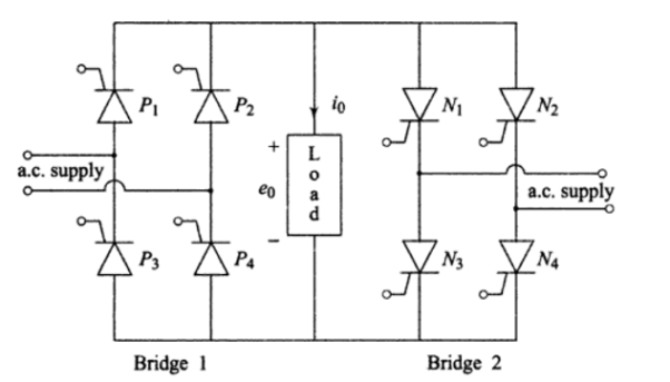
Instead of one thyristor in the centre-tap transformer configuration, two thyristors come in series with each voltage source in the bridge configuration.
For resistive loads, the SCRs undergo natural commutation and produce discontinuous current operation as same as produced in single phases to single phase cyclo-converter.
For inductive loads, the load current may be continuous or discontinuous, depending upon the firing angle and load power factor. The load voltage and current waveforms are similar to single phases to single phase for discontinuous load current and as in single phases to single phase for continuous load current.
When the load current is positive, the firing pulses to the SCRs of bridge 2 will be inhibited and bridge 1 will be gated. Similarly, when the load current is negative, bridge 2 will be gated and the firing pulses will not be applied to the SCRs in bridge 1. This is the circulating current free mode of operation.
Thus, the firing angle control scheme must be such that one converter can conduct at a time, and the change-over of firing pulses from one converter to the other should be periodic according to the output frequency. However, the firing angles of SCRs of both the converters should be the same to produce a symmetrical output.
Cosine Firing Scheme:
This scheme is used to fire thyristors in single phase converter. The pulse output of this scheme synchronizes with AC supply using step down transformer supply voltage step down to an appropriate level.
The input to this transformer is taken from same source from which converter circuit is energized. The output voltage of transformer is integrated using integrator to get cosine wave V1.
The cosine signal is compared with reference voltage in comparator 1 and in comparator 2, it is compared with invert of reference voltage.
The DC control voltage EC varies from maximum positive Ecm to maximum negative Ecm so that firing angle can be varied from 0 to 180 degree.
So, comparator 1 and comparator 2 give output pulses V2 and V3. The firing angle is governed by the intersection of V1 and EC. When EC is a maximum, firing angle is zero. Thus, firing angle in terms of V2m and Ec can be expressed as
V2m cos α = Ec
α = cos -1 (Ec/ V2m)
Or V2m = maximum value of cosine signal V2.
The signals V 3, V4 obtained from comparators is fed to clock pulse generators 1, 2 to get clock pulses V5, V6. These signals V5, V6 energies a JK flip flop to generate output signals Vi and Vj.
The signal Vi is amplified through the amplifier circuit and then employed to turn ‘On’ the SCR’s in the positive half cycle. Signal Vj , after amplification, is used to trigger SCR’s in the negative half cycle.
Firing angle in time is
α =(180 x T) / 10 ms
So,
T = (α X 10ms ) / 180
Where time T in ms .
And VRMS = VM / √2
Then VM = √2 X VRMS
The circuit of a three-phase to three-phase cyclo-converter is shown in Figure.
Two three-phase half-wave (three-pulse) converters connected back to back for each phase, with three thyristors form bridge. The total number of thyristors used is 18, thus reducing the cost of power components, and of control circuits needed to generate the firing pulses for the thyristors.
This may be compared to the case with 6 (six) three-phase full-wave (6-pulse) bridge converters, having six thyristors for each converter, with total devices used being 36. Though this will reduce the harmonic content in both output voltage and current waveforms, the cost is more.
The ripple frequency is 150 Hz, three times the input frequency of 50 Hz. In the figure the circulating current mode of operation is used, in which both (positive and negative) converters in each phase, conduct at the same time.
Inter-group reactor in each phase is shown but for non-circulating current mode of operation only one converter (positive or negative) in each phase, conducts at a time the reactors are not needed.
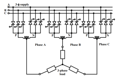
The firing sequence of the thyristors for the phase groups, B & C are same as that for phase group A, but lag by the angle. Thus, a balanced three-phase voltage is obtained at the output terminals are fed to the three-phase load.
The average value of the output voltage is changed by varying the firing angles ( 120° and 240° ) of the thyristors, whereas its frequency is varied by changing the time interval (T/3 ), after which the next (incoming) thyristor is triggered.
With a balanced load, the neutral connection is not necessary, and may be omitted, thereby suppressing all triple harmonics.
An expression for the fundamental component of the phase voltage (rms) delivered by the cyclo-converter
An m-phase converter circuit is assumed in which each phase conducts for
(π /)2( m ) electrical radians in one cycle of supply (input) voltage.
For example, in a three-phase, half-wave (three-pulse) converter (m = 3), each phase conducts for ( 2⋅π/6 = π/3 = 120 ° radians in a cycle of ( 2 ⋅π ) radians.
Similarly, in a three-phase, full-wave (six-pulse) converter (m = 6), the conduction period of the periodic waveform is ( 2⋅π /6 = π /3 = 60 ° radians in one cycle.
The output voltage waveform for an m-phase converter with firing delay angle α , is shown in Figure.
With the time origin, PP ′ taken at the peak value of the supply voltage, the instantaneous phase voltage is given by
e = Em coswt = √2 Eph coswt where Eph = supply voltage per phase.
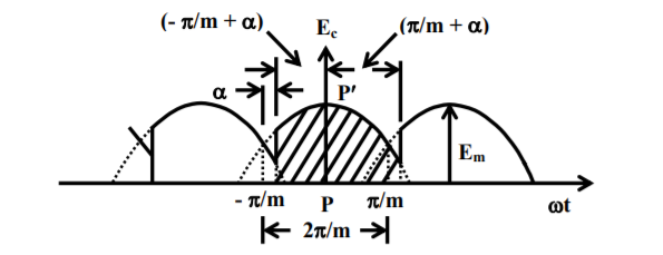
From the figure it is observed that the conduction period is from (-π/m) to (π/m) if the firing delay angle is α = 0 o .
For firing angle delay α the conduction period is from (-π/m) to (π/m) if the firing delay angle is α = 0 o . For the firing delay angle α the conduction period is from (-(π/m) + α) to ((π/m) +α).
The total conduction period is (( 2.π)/m) .
The average value of the output voltage is
Edc = (m/2.π) .  Eph cos wt d(wt) = √2. Eph . (m/π) . sin (π/m) . Cos α
This expression is obtained for dc to ac converter .
When the firing angle α =0 , Edc has the maximum value of
Edo = √2. Eph . (m/π) . Sin (π/m)
From the figure it is observed that the conduction period is from ( −π / m) to (π / m), if the firing delay angle is α= 0° . For the firing delay angle α , the conduction period is from ( π m)/( +− α ) to ( π m)/( +α ).
If Eor is the fundamental component of the output voltage (rms) per phase for the cycloconverter then the peak output voltage for firing angle of 0o is
√2. Eor = Edo = √2. Eph (m/π) . Sin (π/m)
Or Eor = Eph (m/π) . Sin (π/m)
References:
Periodic Control Of Power Electronic Converters (Hb 2016) by Zhou.
Electrical Machines And Drives (Hb 2018) by MELKEBEEK J A