Unit - 3
Sensors and Transducers for Physical Parameters
A temperature sensor is a device, typically, a thermocouple or resistance temperature detector, that provides temperature measurement in a readable form through an electrical signal.
A thermometer is the most basic form of a temperature meter that is used to measure the degree of hotness and coolness.
Temperature meters are used in the geotechnical field to monitor concrete, structures, soil, water, bridges etc. for structural changes in them due to seasonal variations.
A temperature sensor is a device that is designed to measure the degree of hotness or coolness in an object. The working of a temperature meter depends upon the voltage across the diode. The temperature change is directly proportional to the diode’s resistance. The cooler the temperature, lesser will be the resistance, and vice-versa.
The resistance across the diode is measured and converted into readable units of temperature (Fahrenheit, Celsius, Centigrade, etc.) and, displayed in numeric form over readout units.
A thermocouple (T/C) is made from two dissimilar metals that generate an electrical voltage in direct proportion with the change in temperature. An RTD (Resistance Temperature Detector) is a variable resistor that changes its electrical resistance in direct proportion with the change in the temperature in a precise, repeatable and nearly linear manner.
Key Take Aways:
There are four types of temperature sensors that are most commonly used in modern-day electronics: thermocouples, RTDs (resistance temperature detectors), thermistors, and semiconductor based integrated circuits (IC).
Pressure is an expression of force exerted on surface per unit area.
We commonly measure the pressure of liquids, air, and other gases, amongst other things. The standard unit for pressure is the “Pascal”. This is equivalent to one “Newton per meter squared”.
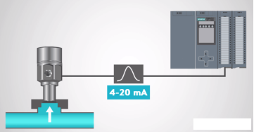
A pressure sensor simply monitors this pressure and display it in one of the several units known around the world. In a nutshell, a pressure sensor converts the pressure to a small electrical signal that is transmitted and displayed.
Most pressure sensors work using the piezoelectric effect. This is when a material creates an electric charge in response to stress. This stress is usually pressure but can be twisting, bending, or vibrations. The pressure sensor detects the pressure and can determine the amount of pressure by measuring the electric charge.
Pressure sensors need to be calibrated so it knows what voltage or milliamp (mA) signal corresponds to what pressure.
|
Figure 1. Pressure sensor
Key Take Aways:
Pressure sensors produce an output voltage that varies with the pressure it experiences, usually referring to the sensor element that is physically detecting the pressure.
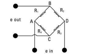
All torque sensors manufactured are strain guage based measuring instrument whose output voltage is proportional to applied torque. The output voltage produced by resistance change in strain guages that are bonded to the torque sensor structure. The magnitude of the resistance change is proportional to the deformation of the torque sensor and therefore the applied torque.
The four-arm wheatstone bridge configuration shown depicts the strain guage geometry used in torque sensor structures. This configuration allows for temperature compensation and cancellation of signals caused by forces not directly applied about the axis of the applied torque.
|
Figure 2. Four arm wheatstone bridge
Key Take Aways:
Torque measurement sensor is a type of transducer, specifically a torque transducer that converts a torque measurement (reaction, dynamic or rotary) into another physical variable, in this case, into an electrical signal that can be measured, converted and standardized.
A flow sensor is an electronic device that measures or regulates the flow rate of liquids and gases within pipes and tubes. Flow sensors are generally connected to gauges to render their measurements they can also be connected to computers and digital interfaces. They are commonly used in HVAC systems, medical devices, chemical factories, and septic systems. Flow sensors can detect leaks, blockages, pipe bursts, and changes in liquid concentration due to contamination or pollution.
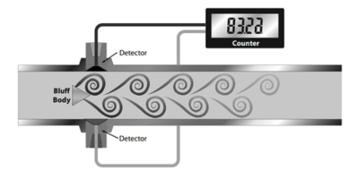
Flow sensors can be divided into two groups: contact and non-contact flow sensors. Contact flow sensors are used in applications where the liquid or gas measured is not expected to become clogged in the pipe when it meets the sensor’s moving parts. In contrast, non-contact flow sensors have no moving parts, and they are generally used when the liquid or gas are being monitored which would be otherwise contaminated or physically altered by coming into contact with moving parts.
|
Figure 3. Vortex Flow sensor
The two most common types of contact flow sensors are vortex and mechanical flow sensors.
Key Take Aways:
A flow sensor is an electronic device that measures or regulates the flow rate of liquids and gasses within pipes and tubes.
The main task of position sensors is the sensing of angular or linear displacements, distances, gaps, distensions and fill levels.
Speed and frequency sensors are used to measure the covered distance or angle per time unit. A major application field is the speed controlling and monitoring of asynchronous drive systems applied in various industries like on- and off-road vehicles, the energy sector, medical sector, automation and machinery sectors. In this field contactless sensors penetrated the market due to the lack of mechanical parts that wear out, yielding a long lifetime.
Key Take Aways:
Speed sensors are employed to measure the speed of engine crankshaft, camshaft and wheel speed in automotive applications
References:
- Biomedical Instrumentation Book by R. S Khandpur and Raghbir Khandpur
- Biomedical Instrumentation and Measurements by Cromwell
- Biomedical Instrumentation And Measurements by Peter and Joseph
- INTRODUCTION TO BIOMEDICAL INSTRUMENTATION by Mandeep Singh


