Unit - 5
Measurements of R,L and C
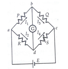
It has four resistive arms, consisting of resistances P, Q R and S together with a source of emf that is battery and null detector galvanometer G or another sensitive current meter. The current through the galvanometer depends on the potential difference between points c and d.
The bridge is said to be balanced when there is no current through the galvanometer or when the potential difference across galvanometer is zero.
The balanced condition occurs when voltage from point b to point a equals to voltage from point d to point b or by referring to the other battery terminal when the voltage from point d to point c equals the voltage from point b to point c.
|
Figure 1. Wheatstone bridge for measurement of medium resistance.
For a balanced condition, we can write, I1 P = I2 R ---------------------(1) For the galvanometer current to be zero, the following conditions also exist: I1 = I3 = E/P+Q-----------------------------(2) I2 = I4 = E/R+S ---------------------------------(3) Combining the above three equations we get, P/P+Q = R/R+S --------------------------------(4) from which Q.R = P.S ----------------------------------------------------------------(5) R = S*(P/Q) |
Key Take Aways:
The Wheatstone Bridge is used to measure unknown resistance values as means of calibrating measuring instruments, voltmeters, ammeters, and so on by the use of a long resistive slide wire.
Problem:
|
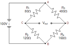
For the first series arm, ACB
Vc = R2/(R1+R2) x Vs Vc = 120Ω/ 80Ω + 120 Ω x 100 = 60 volts For the second series arm, ADB VD = R4/(R3+R4) x Vs VD = 160Ω/ 480Ω + 160Ω x 100 = 25 volts The voltage across points C-D is given as: Vout = VC – VD Vout = 60 -25 = 35 volts The value of resistor, R4 required to balance the bridge is given as: R4 = R2R3/R1 = 120Ω x 480Ω/80Ω = 720 Ω |
A Wheatstone bridge is used for measuring the value of change of resistance of a strain gauge which forms one of the arms of the bridge. All the arms of the bridge including the strain gauge have a resistance of 100 Ω each. The maximum allowable power dissipation from the strain gauge is 250mW. Determine the value of maximum permissible current through the strain gauge and maximum allowable value of bridge supply voltage. Suppose a source of 20V is available find the value of series resistance to be connected between the source and the bridge to limit the input voltage of the bridge to permissible level.
Solution:
The resistance of strain gauge R = 100Ω . Suppose I is the current through each arm under balanced conditions I 2 R = P where P = power dissipation Hence maximum permissible current = The maximum allowable voltage which can be applied to the bridge = 2 x 50 x 10 -3 x 100 = 10V Voltage across the series resistor = 20 – 10 = 10V Current through the series resistor = 2 x 50 x 10 -3 x 100 x 10 -3 Resistance of series resistor Rs = 10/100 x 10 -3 = 100Ω |
Maxwell Bridge
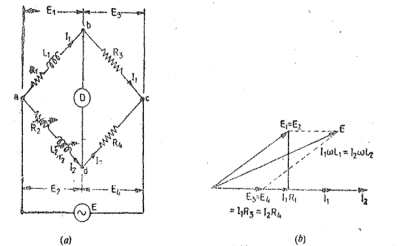
Li =unknown inductance of resistance Ri,
L2=variable inductance of fixed resistance r2,
Ra=variable resistance connected in series with inductor L2, and
R3,R4=known non-inductive resistances .
|
Figure 2 . Maxwells Inductance Bridge
At balance L1 = R3/R4 L2 R1 = R3/R4 (R2+r2) |
|
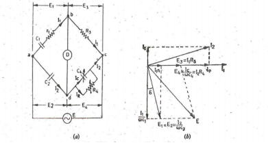
Figure 3. Schering Bridge (low voltage)
Let C1 = capacitor whose capacitance is to be determined
r1 = series resistance representing the loss in the capacitor C1.
C2 = standard capacitor.
R3 = non-inductive resistance
C4 = variable capacitor
R4 = variable non-inductive resistance in parallel with variable capacitor C4.
At Balance (r1+1/jwC1) (R4/ 1+jwC4R4) = 1/jwC2. R3 ( r1 + 1/jwC1) R4 = R3 / jwC2 (1+jwC4R4) r1R4 – jR4/wC1 = -jR3/wC2 + R3R4C4/ C2 Equating real and imaginary terms we obtain r1 = C4/C5 xR3 And C1 = R4/R3 x C2 Two independent balance equations are obtained if C4 and R4 are chosen as the variable elements Dissipation factor D1 = tan ɸ = w C1 r1 = w . R4/R3 . C2 . C4/C2 . R3 = wC4R4 |
Key Take Away:
AC bridges are the circuits that are used for the measurement of electrical quantities such as inductance, capacitance, resistance
References:
- Biomedical Instrumentation Book by R. S Khandpur and Raghbir Khandpur
- Biomedical Instrumentation and Measurements by Cromwell
- Biomedical Instrumentation And Measurements by Peter and Joseph
- INTRODUCTION TO BIOMEDICAL INSTRUMENTATION by Mandeep Singh


