Unit - 6
Digital Multimeter
A digital multimeter (DMM) is a testing tool that measures electrical values: current in amps, voltage in volts and resistance in ohms. Electricians use a digital multimeter as standard diagnostic tool.
The digital counterpart has proven to be more accurate, reliable and has increased impedance compared to its former counterpart. They also combine testing capabilities that were earlier limited to separate voltmeters, ammeters, and ohmmeters.
The face of a digital multimeter usually has four components:
- Display
- Buttons
- Dial for selecting measurement values
- Input jacks
Counts and digits are the terms that define a digital multimeter’s resolution. By knowing the proper resolution, a technician knows whether the multimeter can detect a certain signal.
For example, if a multimeter offers 1mV on a 4V range, one can see a change of 1mV when reading 1V. Digital multimeters also offer additional testing capabilities like frequency, capacitance, and temperature. A multimeter has various purposes; for example, it can be used as a handheld device for field work or it can also be used to measure data in a controlled environment with high accuracy.
Key Takeaways:
A digital multimeter is a test tool used to measure two or more electrical values—principally voltage (volts), current (amps) and resistance (ohms).
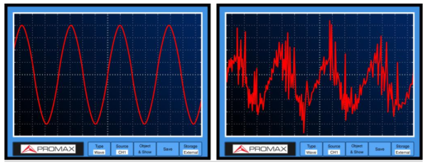
RMS measurements are not reliable because any installation has multiple sources of noise causing the AC waveform to not to be perfect.
The True RMS measurement uses more complex mathematical formulas that allow getting a value closer to reality than the RMS. In addition to peak values, they take several samples of values along each cycle.
V TRMS = √ V1 2 +V2 2+………Vn 2 / n |
|
Figure1. True RMS meter
Key Takeaways:
A true-RMS device (RMS = root mean square) is one of three tools that can measure alternating current (ac) or ac voltage:
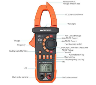
An electrical meter with an integrated AC current clamp is known as a clamp meter, a clamp-on ammeter, a tong tester or, colloquially, an amp clamp.
|
Figure2. Clamp Meter
It measure any of these or we can say it is used to measure following parameters:-
- AC current,
- AC and DC voltage,
- Resistance,
- continuity, and, with some models,
- DC current,
- Capacitance
- Temperature
- Frequency and more
Clamp meters are preferred because it measure of high- level currents.
DMMs will not be able to measure 10 A of current for more than 30 seconds without risking meter damage.
Key Takeaways:
The working principle of clamp meter is the magnetic induction principle to create AC current measurements without contact.
|
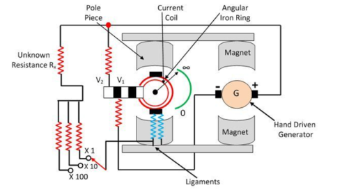
Figure3. Megger
The construction of the Megger is shown in the figure below. The Megger has one current coil and the two voltage coils V1 and V2. The voltage coil V1 is passed over the magnet connected to the generator. When the pointer of the PMMC instrument deflects towards infinity, it means that the voltage coil remains in the weak magnetic field and thus experienced the little torque.
The torque experienced by the coil increases when it moves insides the strong magnetic field. The coil experiences maximum torque under the pole faces and the pointer set at the zero end of the resistance scale.
To improve torque, the voltage coil V2 is used. The coil V2 is so allocated that when the pointer deflects from infinity to zero the coil moves into stronger magnetic field.
In Megger, the combined action of both the voltage coils V1 and V2 are considered. The coil comprises a spring of variable stiffness. It is stiff near the zero end of the coil and becomes very weak near the infinity end of the spring.
The spring compresses the low resistance portion and opens the high resistance of the spring, which is the great advantage of the Megger because it is used for measuring the insulation of the resistance which is generally high.
The instrument has voltage selector switch which is used for selecting the voltage range of the instrument. The voltage range is controlled by selecting the varying resistance R connected in series with the current coil. The voltage is generated by connecting the hand driven generator.
The Megger has three coils two pressure coils and one current coil. The pressure coil rotates the moving coil in the anticlockwise direction, whereas the current coil rotates it in the clockwise direction.
When the unknown resistance is connected in the circuit, the pointer of the moving coil becomes stable. The pressure coil and the current coil balance the pointer and set it in the middle of the scale.
The deflection of the pointer is directly proportional to the voltage applied to the external circuit. When the testing circuit is applied across the Megger, and if there is no shorting throughout the insulation then the pointer deflects towards the infinity. Which shows that the resistance has high insulation. For low resistance, the pointer moves towards zero.
Key Take Aways:
The Megger is the instrument uses for measuring the resistance of the insulation.
References:
- Biomedical Instrumentation Book by R. S Khandpur and Raghbir Khandpur
- Biomedical Instrumentation and Measurements by Cromwell
- Biomedical Instrumentation And Measurements by Peter and Joseph
- INTRODUCTION TO BIOMEDICAL INSTRUMENTATION by Mandeep Singh


