The digital oscilloscope digitises and stores the input signal which can be done by the use of CRT and digital memory. The block diagram of the basic digital oscilloscope is shown in the figure below. The digitisation can be done by taking the sample input signals at periodic waveforms.
|
Figure1. Digital storage Oscilloscope
The maximum frequency of the signal which is measured by the digital oscilloscope depends on the two factors. These factors are the
- Sampling rate
- Nature of converter.
Sampling Rate – For safe analysis of input signal the sampling theory is used. The sampling theory states that the sampling rate of the signal must be twice as fast as the highest frequency of the input signal. The sampling rate means analogue to digital converter has a high fast conversion rate.
Converter – The converter uses the expensive flash whose resolution decreases with the increases of a sampling rate. Because of the sampling rate, the bandwidth and resolution of the oscilloscope are limited.
The need of analogue to digital signal converters can also be overcome by using the shift register. The input signal is sampled and stored in the shift register. From the shift register, the signal is slowly read out and stored in the digital form. This method reduces the cost of the converter and operates up to 100 mega sample per second.
The only disadvantage of the digital oscilloscope is that it does not accept the data during digitisation, so it had a blind spot at that time.
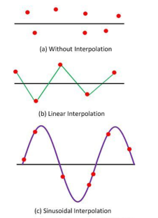
Waveform Reconstruction
|
In interpolation, the lines are used for connecting the dot together. Linear interpolation is also used for creating the pulsed or square waveform. For sine waveform, the sinusoidal interpolation is utilised in the oscilloscope.
References:
- Biomedical Instrumentation Book by R. S Khandpur and Raghbir Khandpur
- Biomedical Instrumentation and Measurements by Cromwell
- Biomedical Instrumentation And Measurements by Peter and Joseph
- INTRODUCTION TO BIOMEDICAL INSTRUMENTATION by Mandeep Singh

