Unit - 1
Introduction and Components of a Protection System
A protection scheme in a power system is designed to continuously monitor the power system to ensure maximum continuity of electrical supply with minimum damage to life, equipment, and property. While designing the protective schemes, one has to understand the fault characteristics of the individual components of a power system. One must also be equipped with the knowledge of tripping characteristics of relays. The protection engineers are hence required to obtain a closest possible match between the fault characteristics and tripping characteristics. Their job is to ensure that the relays in the system detect undesirable conditions and then trip to disconnect the area affected, but are restrained all other times. However, there is statistical evidence that a large number of relay trippings are due to improper or inadequate settings than due to genuine faults.
Protection Fundamentals
- What is Protection?
Avoiding the undesirable effects of abnormal electrical system behavior by appropriate action.
- What is Protected?
Equipment, Personnel, System Stability
- Why are they Protected?
To prevent damage to life, property and prevent hazards (due to arcs and flashes)
- How are they Protected?
Protective equipments detect the abnormal conditions in the system and quickly disconnect the healthy parts of the system without any delay.
The modern society depends heavily upon continuous availability of electricity and a high quality of electricity too. Computer and telecommunication networks, railway networks, banking and post office networks, continuous and process industries and life support systems are just a few applications. The life of domestic users can come to a standstill if high quality and continuous power supply is not provided. Thus, the importance of maintaining continuous supply of electricity round the clock cannot be overemphasized.
A good electric power system should ensure the availability of electrical power without any interruption to every load connected to it. Generally, power is transmitted through high voltage transmission line and lines are exposed, there may be chances of their breakdown due to storms, falling of external objects, and damage to the insulators etc. These can result not only mechanical damage but also in an electrical fault.
The following protection schemes are used in a power system-
a) Over Current Protection Scheme
b) Differential Protection Scheme
c) Distance Protection Scheme
d) Directional Protection Scheme
Power System Protection: Basic Attributes
Every protective system which isolates a faulty element must satisfy four basic
Requirements:
1. Reliability
2. Selectivity
3. Fastness of operation
4. Discrimination
Reliability
Reliability is a qualitative term. It can be expressed as a probability of failure.
- Quality of personnel i.e. mistakes by personnel are most likely causes of failure.
- High contact pressure
- Dust free enclosures
Records show that the order of likelihood of failure is relays, breakers, wiring, current transformers, voltage transformers and battery. When relays using transistors are considered, the failure rate goes up still further.
Selectivity
The property by which only the faulty element of the system is isolated and the remaining healthy sections are left intact. Selectivity is absolute if the protection responds only to faults within its own zone and relative if it is obtained by grading the setting of protections of several zones which may respond to a given fault.
Fastness of Operation
Protective relays are required to be quick acting due to the following reasons:
(a) Critical clearing time should not be exceeded.
(b) Electrical apparatus may be damaged, if they are made to carry fault currents for a long time.
(c) A persistent fault will lower the voltage resulting in crawling and overloading of
Industrial drives.
Discrimination
- Protection must be sufficiently sensitive to operate reliably under minimum fault condition for a fault within its own zone while remaining stable under maximum load i.e. a relay should be able to distinguish between a fault and an overload.
- In the case of transformers, the inrush of magnetising current may be comparable to the full current, being 5 to 7 times the full load current. The relay should not operate for inrush current.
- In interconnected systems, there will be power swing, which should also be
Ignored by the relay.
Components of Protection
Some of the commonly used components of the protective schemes are:
- Relays
- Circuit Breakers
- Tripping and Auxiliary Supplies
- Current Transformers
- Voltage Transformers
When any abnormal condition develops, the main function of a protective relay is to isolate the faulty section with the least interruption to the service by controlling or operation the circuit breaker. The relay may be designed to detect and to measure abnormal condition and close the contacts of the tripping circuit.
The two categories of relay are most commonly used in protective relay:
- Secondary indirect acting relays
Example: Current, Voltage, Power, Impedance, Reactance and frequency
Whether minimum or maximum.
- Secondary directing acting relay
A group of over current and under voltage relays designed to operate
Immediately or with time lag.
Relay classification
The actuating quantity is normally in electrical signal. Sometimes the actuating quantity may be pressure and temperature.
Protective relay can be classified as
- According to the function in protection scheme.
- According to the nature of actuating quantity.
- According to the connection of the sensing element
- According to the method by which the relay acts upon the circuit breaker
Generally the electrical protective relays can be broadly classified in two categories:
(a) Electromagnetic relays
(b) Static relays
The static relays are classified according to the types of measuring units or the comparator
1) Electronic relays
2) Transducer(magnetic amplifier relay)
3) Rectifier bridge relay
4) Transistor relay
5) Hall effect relay
6) Gauss effect relay
Principal types of electromagnetic relays
There are two types of electromagnetic relays
a) Attracted armature type
b) Induction type
Attracted armature type- This includes plunger, hinged armature, balanced beam and moving iron polarized relay. These are simplified types which respond to A.C as well as D.C.
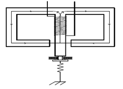
Figure 1 – Plunger
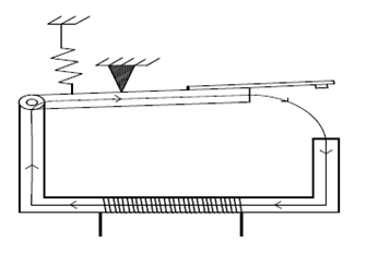
Figure 2 – Hinged Armature

Figure 3 – Balanced beam type
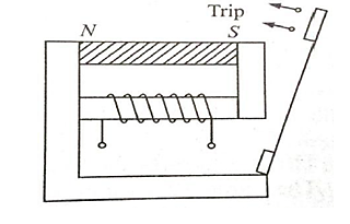
Figure 4 -Polarized iron moving type
In dc the electromagnetic force exerted on the moving element is proportional to the square of the flux or square of the current. In dc electromagnetic relay this force is constant. If this force exceeds the restraining force, the relay operates.
In ac electromagnetic relays the electromagnetic force is given by:


This indicates that the electromagnetic force consists of two components:
(i) One constant independent of time and
(ii) Another dependent on time and pulsating at double the frequency of the applied alternating quantities.
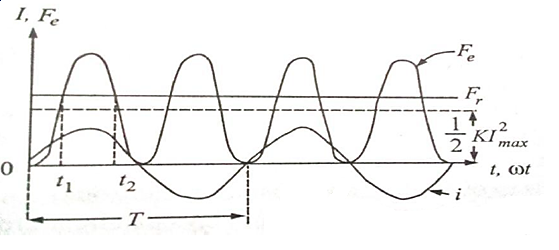
Figure -5
The total electromagnetic force pulsates at double the freq. The force is plotted graphically which shows that Fe = 0 in every half period.
If Fr is produced with the help of a spring then it is constant. Then the relay armature will be picked up at t1 and the armature drops off at t2. Hence the armature vibrates at double the frequency. This causes the relay to hum and produces noise and also is a source of damage to relay contacts. This leads to sparking and unreliable operation of the relay operating circuit contacts due to make and break of the circuits.
To overcome this difficulties in ac electromagnetic relay the flux that produce electromagnetic force is divided into two fluxes among simultaneously but differing in time phase. So that the resultant electromagnetic force is always positive and this is always greater the restraining force so that the armature will not vibrate. This is achieved through shaded pole or by providing two windings having a phase shift.
The flux through the shaded pole lags behind the unshaded pole. In case of balanced beam type two quantities A and B are compared. Actually |A|2 and |B|2 are compared because the electromagnetic forces are proportional to (ampere turns)2. It has low ratio of reset by operating current.
Sensitivity of hinged armature relays can be increased for dc operation by the addition of a permanent magnet. This is known as a polarised moving iron relay.
Induction type relay
An induction relay essentially consists of aluminium disc placed in two alternating magnetic flux of same frequency but displaced in time and space. The torque is produced in the disc by the interactions of one of the magnetic field with the currents induced in the disc by the other. Induction relays are widely used for protective relaying involving AC quantities. High, low and adjustable speeds are possible and the various shapes of time/operating curve can be obtained.
Types of structure
(a) Shaded pole - It consists of pivoted aluminium disc free to rotate in the air gap of an electro magnet. One half is surrounded by copper band known as shaded ring.
The alternating flux in the shaded portion of the poles will lag behind the flux in the unshaded portion by an angle α due to the reaction of the current induced in the ring.
These two a.c fluxes differing in phase will produce the necessary torque to rotate the disc.
(b) Wattmeter structure or double winding structure - In the wattmeter type these are two magnetic systems. A phase displacement between the fluxes is obtained either by having different inductance and resistance for the two circuits or energizing these from two different sources whose outputs are relatively displaced.
(c) Induction cup structure - The rotating field is produced by two pairs of coils wound on four poles. The rotating field induced current in the cup to provide the necessary driving torque.
If Φ1 and Φ2 represent the fluxes produced by the respective pair of poles, then the torque produced is proportional to Φ1. Φ2 sinα i.e T α Φ1.Φ2 sinα
A control spring and the back stop is provided for closing of the contacts that are attached to the spindle of the cup to prevent the continuous rotation. Induction cup structure is more efficient torque producers than shaded pole and wattmeter type. So this type of relay has very high speed. The operating time is less than 1 second.
Relay design and construction
The design of protective relay is normally divided into the following stages:
(a) Selection of the operating characteristics
(b) Selection of proper construction
(c) Design of the contact moment from the point of view of utmost reliability.
The relay operating characteristic must match with the abnormal operating characteristics of the system i.e. it should clearly show the conditions for tripping under various abnormal operating conditions.
The most important considerations in the design for construction are:
- Reliability
- Simplicity of construction
- Circuitry
The construction of the relay is divided into the following:
i. Contacts
Ii. Bearing
Iii. Electromechanical design
Iv. Termination and housing
Contacts
Contact performance is probably the most important item affecting reliability of the relay. Corrosion or dust deposit can cause non-operation of relay. Thus material and shape of relay are of considerable importance. A good contact system design provides restricted contact resistance, reduced contact wear. The contact material used are gold, gold alloy, platinum, palladium and silver.
The selection of the contact material depends on a number of factors like:
- The voltage per contact break
- The current to break
- The type of atmospheric pollution under which the contacts are operate
The following factors are to be considered for selecting a suitable contact material:
1) The nature of the current to be interrupted (ac or dc)
2) Voltage at break and make operation
3) Value of current magnitude
4) Frequency of operation
5) The actual speed of contact at make or break
6) Contact shape
Some rules or points recommended in the design of contact system of a relay:
(a) The contacts should be bounce proof to avoid arcing at the contacts.
(b) There should be increased contact-pressure that leads to decrease in voltage drop or contact resistance.
c) To promote accuracy and avoid sticking after a long period of inaction. So the relay should be designed to have maximum torque/friction ratio.
(d) The value of current that can be interrupted by a pair of contacts in ac circuit is 2 to 8 times than in a dc circuit.
Generally dome shaped contacts give best performances.
Bearing
(a) Single ball bearing
(b) Multi ball bearing
(c) Pivot and jewel bearing – This is the most common type for precision relay.
Electromechanical Design
It consists of the design of the magnetic circuit and the mechanical features of core, yoke, and armature. The reluctance of the magnetic path is kept to a minimum by enlarging the pole face which makes the magnetic circuit more efficient.AC electromagnets made from soft iron, low carbon steel core having a slot for mounting shaded rings are more common.
The relay coil current is usually limited to 5A and the coil voltage to 220 V but the
Insulation for the relay coil is designed to withstand at least 4kV.The relay coil is designed to carry about 15 times the normal current foe one second.
Termination and housing
Material used for springs are stainless steel, nickel steel, phosphorous bronze and Beryllium copper.
The spring is insulated from the armature by moulded blocks. For moulded blocks nylon is used.
Current Transformer
The current transformer (CT) has two jobs to do. Firstly, it steps down the current to such levels that it can be easily handled by the relay current coil. The standard secondary current ratings used in practice are 5 A and 1 A. Secondly, it isolates the relay circuitry from the high voltage of the EHV system.
The primary winding of the CTs is connected in series with the load and carries the actual power system current (normal or fault). The secondary is connected to the measuring circuit or the relay.
Ideally, the current transformer should be able to transform the current without any errors. However, there is always some error. The error comes across, both in magnitude and in phase angle. These errors are known as ratio error and phase angle error.
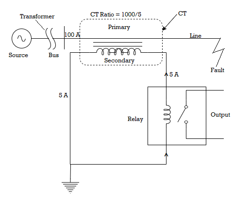
Figure 6- Current Transformer
The current transformers are used for metering purposes as well. However, there is a very important difference between a metering CT and a protection CT. A metering CT is so designed that in case of faults, it will saturate and thus save the instrument connected to its secondary from damage due to excessive current. On the other hand, a protective CT is designed to reproduce the largest fault current.
Grain oriented steels having high saturation level are used as core materials for protective CTs and nickel iron alloys for measuring CT’s.
Voltage Transformer
It is not possible to connect the voltage coils of the protective device directly to the system in case of high voltage systems. So it is necessary to step down the voltage, also to insulate the protective equipment from primary circuit. This is achieved by using a voltage transformers. Also known as potential transformer (PTs) which is similar to a power transformer. The voltage transformer is rated in terms of the maximum burden (VA) output it delivers without exceeding specified limits of errors. Whereas the power transformer is rated by the secondary output it delivers without exceeding a specified temperature rise.
The output of PTs is usually limited to a few hundred volt amperes and the secondary
Voltage is usually 110V between phases. Ideally a VT should produce a secondary voltage exactly proportion al to the primary voltage and exactly in phase opposition. This cannot obviously be achieved in practice owing to the voltage drops in the primary and secondary coil due to the magnitude and power factor of the secondary burden. Thus ratio errors and phase angle errors are introduced.
There are two types of Voltage devices
a) The conventional wound type voltage transformers up to (132kV)
b) Capacitor Voltage Transformer (>132 kV)
When appreciable current flows in the burden both ratio and phase are introduced because of the load current flowing through the capacitor C1. The voltage drop on load due to reluctance of the capacitors can be compensated by inserting an inductance reactance in series with the load.
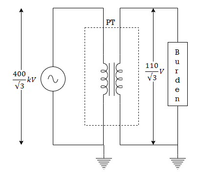
Figure 7 – Voltage Transformer
It is desirable to switch on or off the various circuits like transmission line, distributors generating plants under both normal and abnormal condition. This can be done by a switch and a fuse but the limitations are:
1. It take some time to replace
2. It cannot successfully interrupt heavy fault current. So, we use Circuit Breaker.
The circuit breaker is an electrically operated switch, which is capable of safely making, as well as breaking, short-circuit currents. The circuit breaker is operated by the output of the associated relay. When the circuit breaker is in the closed condition, its contacts are held closed by the tension of the closing spring. When the trip coil is energized, it releases a latch, causing the stored energy in the closing spring to bring about a quick opening operation.
The circuit breaker contacts are in a closed position by the force of a spring. Energy is stored in the spring during the closing operation. In order to trip the circuit breaker, it is necessary to release a latch either manually or by energizing the trip-coil of the circuit breaker. The trip-battery supplies energy to the trip-coil for this operation. The relay output contact is wired in series with the trip-battery and the trip-coil. Thus when the relay operates, the trip-coil gets energized and the circuit breaker quickly parts it’s contacts. The mechanical arrangement is quite complicated and is shown below.
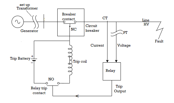
Figure 8 - CB Tripping Circuit
References:
1. J. L. Blackburn, “Protective Relaying: Principles and Applications”, Marcel Dekker, New York, 1987.
2. Y. G.Paithankar and S. R. Bhide, “Fundamentals of power system protection”, Prentice Hall, India, 2010.
3. A. G. Phadke and J. S. Thorp, “Computer Relaying for Power Systems”, John Wiley & Sons, 1988.
4. A. G. Phadke and J. S. Thorp, “Synchronized Phasor Measurements and their Applications”, Springer, 2008.
5. D. Reimert, “Protective Relaying for Power Generation Systems”, Taylor and Francis, 2006.