Unit - 2
Faults and Over-Current Protection
Nature & Causes of Fault
When the path of the load current is cut short because of breakdown of insulation, we say that a 'short circuit' has occurred. The insulation can break down due to a variety of reasons.
The nature of fault simply implies any abnormal condition which causes a reduction in the basic insulation strength between phase conductors, between phase conductor and earth or any earth screen surrounding the conductors.
The reduction of the insulation is not considered as a fault until it produces some effect on the system i.e. until it results either in an excess current or in the reduction of the impedance between the conductors, between the conductor and earth to a value below the lowest load impedance normal to the circuit.
Power systems mainly consist of generator, switch gear, transformer and distribution system. The probability of failure is more on the power system due to their greater length and exposure to atmosphere.
Breakdown may occur at normal voltage, on account of:
- The deterioration of insulation
- Damage due to unpredictable causes such as perching of birds, accidental short-circuiting by snakes, tree branches, etc.
Breakdown may occur because of abnormal voltages, this may happen because of:
- Switching surges
- Surges caused by lightning
Shunt Faults or Short-circuits are basically caused due to insulation failure. The insulation may break due to it’s own weakening, or it may fail due to overvoltage. The weakening of insulation may be due to one or more reasons and they are listed below:
- Ageing
- Temperature
- Rain, hail, snow
- Chemical pollution
- Foreign objects
- Other causes
The present practice is to provide a high insulation level of the order 3 to 5 times the normal voltage, but still:
- The pollution on an insulator string caused by deposited soot or cement dust in industrial area.
- Salt deposited wind borne see spray in coastal area.
These will initially lower the insulation resistances and causes a small leakage current to be diverted, thus hastening the deterioration.
Secondly, even if the insulation is enclosed, such as sheathed and armoured, the deterioration of the insulation occurs because of:
- Ageing
- Void formation in the insulation compound of underground cable due to unequal expansion and contractions caused by the rise and fall of temperature.
Thirdly, insulation may be subjected to transient over voltages because of switching
Operation.
- The voltage which rises at a rapid rate may achieve a peak value which approaches three times phase to neutral voltages.
- Lightning produces very high voltage surges in the power system in the order of million volts. These surges travel with the velocity of light in the power circuit. The limiting factors are the surge impedance and the line resistance.
Effects of Faults
Serious consequences of faults may occur if they are not cleared on time. It may cause fire, spread into the system and cause total failure.
Faults causes heavy currents to flow. If these fault currents persist even for a short time, they will cause extensive damage to the equipment that carry these currents. Over-currents cause overheating and hence there is a threat of fire. Overheating also causes deterioration of the insulation, thus weakening it further.
Also, excessive mechanical forces develop due to over-currents which causes mechanical damage. Transformers suffer mechanical damage to their windings, due to faults. This is due to the fact that any two current-carrying conductors experience a force. This force goes out of bounds during faults, causing mechanical distortion and damage.
Further, in an interconnected system, there is another dimension to the effect of faults. The generators in an interconnected power system must operate in synchronism at all instants. The electrical power output from an alternator near the fault drops sharply. However, the mechanical power input remains substantially constant at its pre-fault value. This causes the alternator to accelerate. The rotor angle  starts increasing. Thus, the alternators start swinging with respect to each other. If the swing goes out of control, the alternators will have to be tripped out. Thus, in an interconnected power system, the system stability is at stake. Therefore, the faults need to be isolated as selectively and as speedily as possible.
Classification of Faults
Those faults, which involve only one of the phase conductors and ground, are called
Ground faults. Faults involving two or more phase conductors, with or without ground, are called phase faults.
Power systems have been in operation for over a hundred years now. Accumulated experience shows that all faults are not equally likely. Single line to ground faults (L-G) are the most likely whereas the fault due to simultaneous short circuit between all the three lines, known as the three-phase fault (L-L-L), is the least likely.
Fault statistics with reference to type of fault:
Fault statistics with reference to power system elements
Fault | Probability of occurrence (%) | Severity |
L-G | 85% | Least severe |
L-L | 8% |
|
L-L-G | 5% |
|
L-L-L | 2% | Most severe |
Total | 100% |
|
The severity of the fault can be expressed in terms of the magnitude of the fault current and hence its potential for causing damage. In the power system, the three-phase fault is the most severe whereas the single line-to-ground fault is the least severe.
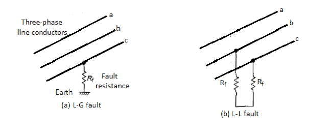
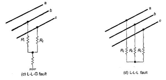
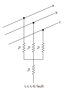
Figure (a-e) various ground faults and phase faults
Single Line to Ground Fault
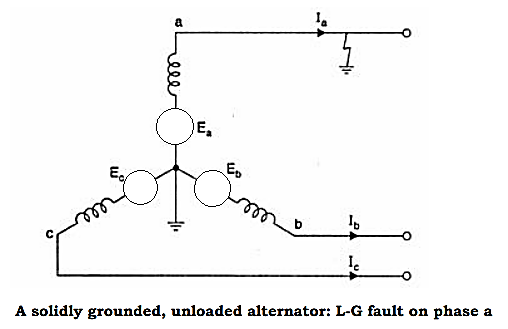
The system to be analyzed is given below. If there is a line-to-ground fault at phase a, the boundary conditions are-

The sequence network equations are:


The solution of these six equations will give all the six sequence components of voltage and current. From the sequence current equations:


Substituting the values of Ib & Ic in the above equations:

Similarly, according to symmetrical component of voltage:

Substituting the values of sequence voltages from the sequence network equation,

Since, 
The above equation becomes-


From the above equation it is evident that to simulate an L-G fault all the three sequence networks are required, and all these sequence networks are to be connected in series, as the sequence currents are equal in magnitude and phase. The interconnection is shown in the figure below-
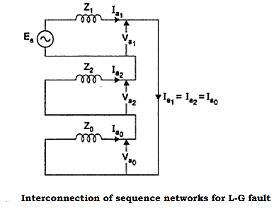
Line to Ground Fault with Zf
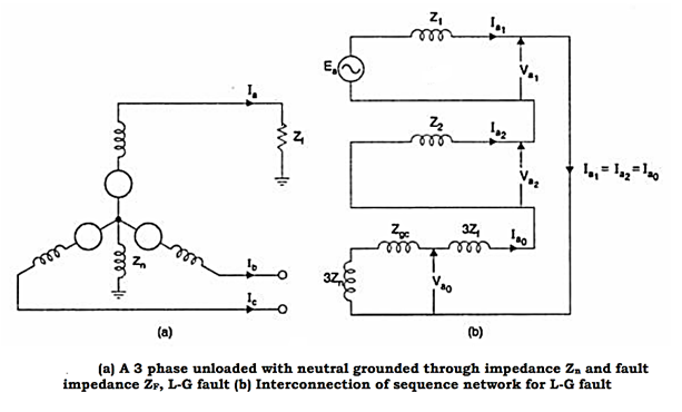
When the fault impedance and the neutral impedance are included, the analysis of the single line to ground fault can be analyzed as follows. The boundary conditions are-


From the above equations, the sequence components can be derived as


The fault diagram and the interconnection is given below:
Line to Line faults (L – L faults)
Line-to-Line faults may occur in a power system, with or without the earth, and with or without fault impedance.
(a) L-L fault with no earth and no Zf

Solution of the L-L fault gives a simpler solution when phases b and c are considered as the symmetrical component matrix is similar for phases b and c. The complexity of the calculations reduce on account of this selection. At the fault,
Ia = 0, Vb = Vc and Ib = – Ic
Mathematical analysis may be done by substituting these conditions to the relevant symmetrical component matrix equation. However, the network solution after converting the boundary conditions is more convenient and will be considered here. Ia = 0 and Ib = – Ic when substituted into the matrix equation gives:

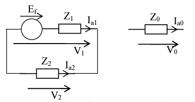
Which on simplification gives Ia0 = 0, and Ia1 = – Ia2 or Ia1 + Ia2 = 0 and Vb = Vc on substitution gives:

Which on simplification gives Va1 = Va2 The boundary conditions Ia0 = 0, Ia1 + Ia2 = 0, and Va1 = Va2 indicate a solution where the two networks positive and negative are in parallel and the zero sequence on open circuit, as given in figure:
(b) L-L-G fault with earth and no Zf
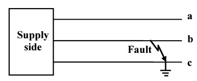
At the fault,
Ia = 0, Vb = Vc = 0 gives
Ia0 + Ia1 + Ia2 = Ia = 0
And the condition
Va0 = Va1 = Va2 (can be shown).
These conditions taken together, can be seen to correspond to all three sequence networks connected in parallel.
(c) L-L-G fault with earth and Zf
If Zf appears in the earth path, it could be included as 3Zf, giving (Z0 + 3Zf) in the zero sequence path.
(d) L-L fault with Zf and no earth
If Zf appears in the fault path, between phases b and c, it could be included as ½ Zf in each of b and c. Inclusion of ½ Zf in a having zero current would not affect it, so that in effect, ½ Zf can be added to each of the three phases and hence to each of the 3 sequence networks as (Z1+½ Zf), (Z2 +½ Zf) and (Z0+½ Zf). The normal circuit analysis would have yielded the positive and negative sequence networks in parallel with a connecting impedance of Zf, which is effectively the same.
The sequence impedance network is defined as a balance equivalent network for the balance power system under an imagined working condition so that only single sequence component of voltage and current is present in the system. The symmetrical components are useful for computing the unsymmetrical fault at different points of a power system network. The positive sequence network determines the load flow studies in power system.
Every power system has three sequence network (positive, negative and zero sequence networks) and these networks carrying three sequence current. These sequence currents interconnect in different ways to represent a different unbalance fault condition. These sequence current and voltage are calculated during the fault due to which actual current and voltage can be determined.
The positive network is considered in the analysis of symmetrical fault. The positive sequence network is the same as that of the sequence reactance or impedance network. The negative sequence network is similar to the positive sequence network only difference is that the negative sequence network is of opposite sign to that of the positive sequence impedance. The zero sequence network will be internally free of the internal fault point and the flow of current being caused by the voltage at the fault point.
Symmetrical Components
A system of three unbalanced phasors can be resolved in the following three symmetrical components:
- Positive Sequence: A balanced three-phase system with the same phase sequence as the original sequence.
- Negative sequence: A balanced three-phase system with the opposite phase sequence as the original sequence.
- Zero Sequence: Three phasors that are equal in magnitude and phase.
Fig. Depicts a set of three unbalanced phasors that are resolved into the three sequence components mentioned above. In this the original set of three phasors are denoted by Va , Vb and Vc , while their positive, negative and zero sequence components are denoted by the subscripts 1, 2 and 0 respectively. This implies that the positive, negative and zero sequence components of phase-a are denoted by Va1 , Va2 and Va0 respectively. Note that just like the voltage phasors given in Fig. We can also resolve three unbalanced current phasors into three symmetrical components.
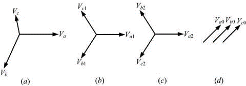
Representation of (a) an unbalanced network, its (b) positive sequence, (c) negative sequence and (d) zero sequence.
The symmetrical component transformation matrix is then given by:

Positive Sequence Network in Power System
In a given power system the positive sequence network shows all the parts for the flow of positive-sequence currents in the systems. It is represented by one line diagram and is composed if impedances offered to the positive sequence network of a given power systems. The following points may possibly be kept in view:
- Each generator in the system is represented by the generated voltage in series with proper reactance and resistance.
- Current limiting impedances between the generator neutral and ground pass no positive sequence current and so are not included in the positive sequence network.
- All resistances and magnetizing currents for each transformer are neglected as a matter of simplicity.
- For transmission lines, the shunt-capacitances and the resistances are generally neglected
- Motor loads are integrated in the network as generated emf in series with appropriate reactance.
Negative Sequence Network in Power System
In a given power system the negative-sequence network shows all the paths for the flow of negative sequence currents in the system. It is also represented by one line diagram and is composed of impedances offered to the negative sequence currents. In the power system the negative-sequence network can be readily obtained from positive sequence network with the following modifications:
- Omit the e.m.f.s of 3-phase generators and motors in the positive sequence network. It is because these devices have only positive-sequence generated voltages.
- Change, if necessary, the impedances that represent rotating machines in the positive sequence network. It is because negative sequence impedances of rotating machinery are generally different from that of positive sequence impedances.
- Current limiting impedances between generators neutral and ground pass no negative sequence current and so are not included in the negative sequence network.
- For static devices such as transmission lines and transformers, the negative sequence impedances have the same value as the corresponding positive sequence impedances.
Zero Sequence Network in Power System
In a given power system the zero sequence networks shows all the paths for the flow of zero-sequence currents. The zero sequence networks depend upon the type of connections of the three phase windings of the components in the system. The following points may be noted about zero sequence networks:
- The zero sequence currents will flow only if there is a return path i.e., path from neutral to ground or to another neutral point in the circuit.
- In the case of a system with no return path for zero sequence currents, these currents cannot exists.
Sequence Circuit for a Y-Connected Load
Consider the balanced Y-connected load that is shown in Figure. The neutral point (n) of the windings are grounded through an impedance Zn. The load in each phase is denoted by ZY. Let us consider phase-a of the load. The voltage between line and ground is denoted by Va, the line-to-neutral voltage is denoted by Van and voltage between the neutral and ground is denoted by Vn.
The neutral current is then 
Therefore, there will not be any positive or negative sequence current flowing out of the neutral point.
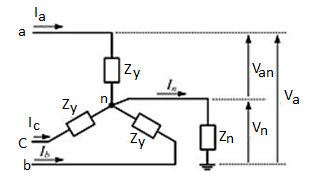

The zero, positive and negative sequence voltages only depend on their respective sequence component currents. The sequence component equivalent circuits are shown in figure below. While the positive and negative sequence impedances are both equal to ZY, the zero sequence impedance is equal to

If the neutral is grounded directly (i.e., Zn = 0), then Z0 = ZY. On the other hand, if the neutral is kept floating (i.e., Zn = ∞ ), then there will not be any zero sequence current flowing in the circuit at all.

Sequence circuits of Y-connected load: (a) positive, (b) negative and (c) zero sequence
Sequence Circuit for a  -Connected Load
Consider the balanced Δ -connected load shown in the given figure, in which the load in each phase is denoted by ZΔ.
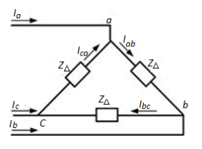
Schematic diagram of a balanced Δ -connected load
The line-to-line voltages are given by:


Adding these three voltages we get

Denoting the zerosequence component Vab, Vbc and Vca as Vab0 and that of Iab, Ibc and Ica as Iab0, we can rewrite the above equation as:

Since 
We can say that, Vab0 = Iab0 = 0. Hence, a Δ -connected load with no mutual coupling has not any zero sequence circulating current. Note that the positive and negative sequence impedance for this load will be equal to ZΔ.
Sequence Circuit for a Synchronous Generator
The three-phase equivalent circuit of a synchronous generator is shown in figure below with the neutral point grounded through a reactor with impedance Zn. The neutral current is then given by:

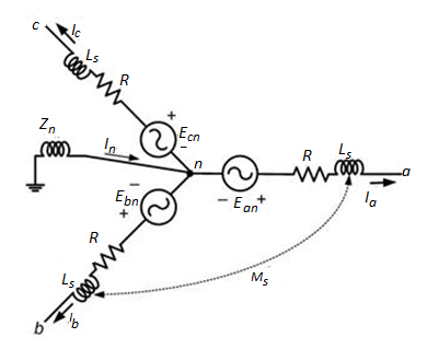
Equivalent circuit of a synchronous generator with grounded neutral


Furthermore we have seen for a Y-connected load that Va1 = V an1, Va2 = Van2 since the neutral current does not affect these voltages. However Va0 = Van0 + Vn. Also we know that Vn = - 3ZnIa0. We can therefore rewrite as:

The sequence diagrams for a synchronous generator are shown:

Sequence circuits of synchronous generator: (a) positive, (b) negative and (c) zero sequence
Sequence Circuit for Transmission lines and cables
The transmission line (or cable) may be represented by a single reactance in the single-line diagram.
Typically, the ratio of the zero sequence impedance to the positive sequence impedance would be of the order of 2 for a single circuit transmission line with earth wire, about 3.5 for a single circuit with no earth wire or for a double circuit line.
For a single core cable, the ratio of the zero sequence impedance to the positive sequence impedance would be around 1 to 1.25.
Transmission lines are assumed to be symmetrical in all three phases. However, this assumption would not be valid for long un-transposed lines (say beyond 500 km) as the mutual coupling between the phases would be unequal, and symmetrical components then cannot be used.
Sequence Impedance: Like the symmetrical components for the current, voltage and power, the impedances are also composed of symmetrical components known as the sequence impedances. These can be defined as follows: The positive sequence impedance of equipment is the impedance offered by the equipment to the flow of positive sequence current. Similarly, the negative and zero sequence impedance of the equipment is the impedance offered by the equipment to the flow of corresponding sequence currents.
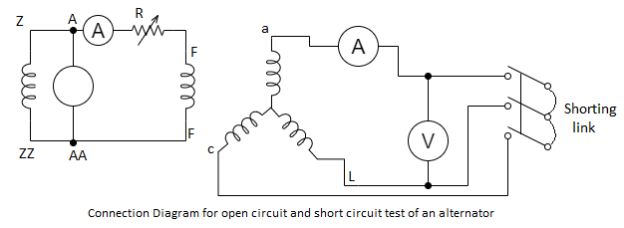
Measurement of positive sequence impedance: The positive sequence impedance depends upon the working of the machine, i.e., whether it is working under sub transient, transient or steady state condition. The impedance measured under steady state is known as synchronous impedance and is measured by the well-known open circuit and short circuit test. The impedance is defined as
Synchronous impedance in p.u=

Measurement of Negative sequence Reactance: It is the impedance offered to the flow of negative sequence current.
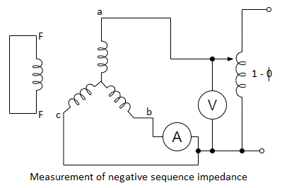
The machine here is driven at rated speed, and a reduced voltage is applied till the rated current flows in the armature. When there is a flow of negative sequence current there may be a possibility of hunting which would cause the pointer to deflect. This allows the mean reading to be taken. The negative sequence impedance is given by:

Where V is the voltmeter and I is the ammeter reading.
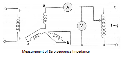
Measurement of zero sequence impedance: Zero sequence impedance is the impedance offered by the machine to the flow of zero sequence current. This impedance depends on the distribution of the windings on the factors like pitch and breadth factors. The value is much smaller as compared to zero and negative sequences.
Method of test for Synchronous Impedance: The machine here is run at a proper direction with the help of a prime mover. The shorting link switch is kept in off position to perform open circuit test and noted the readings of the voltmeter by varying the field current. Similarly, the short circuit test is done by putting the shorting switch on and noting the readings of armature current with the variation of the field current.
Introduction
The most obvious effect of a shunt fault is a sudden build up of current. Therefore, it is only natural that the magnitude of current be utilized as a positive indication of existence of a fault. The over-current protection is the most widely used form of protection. In many situations, it may be the only protection provided. This type of protection which depends on only the magnitude of the current, without taking any cognizance of its phase angle, is known as the non-directional over-current protection.
However, many times it is required to discriminate between faults in front of the breaker and faults behind the breaker. This is possible only if we take into account, not only the magnitude of the current but also its phase with respect to the voltage at the relay location. In such cases, the protection is known as the directional over-current protection.
Zones of Protection
An electric power system is divided into several zones of protection. Each zone of protection contains one or more components of a power system in addition to two circuit breakers. When a fault occurs within the boundary of a particular zone, then the protection system responsible for the protection of the zone acts to isolate (by tripping the Circuit Breakers) every equipment within that zone from the rest of the system. The circuit Breakers are inserted between the component of the zone and the rest of the power system. Thus, the location of the circuit breaker helps to define the boundaries of the zones of protection. Different neighboring zones of protection are made to overlap each other, which ensure that no part of the power system remains without protection. However, occurrence of the fault with in the overlapped region will initiate a tripping sequence of different circuit breakers so that the minimum necessary to disconnect the faulty element.
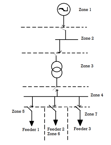
Following six categories of protection zones are possible in a system; we apply here a concept of selective coordination.
- Generators and generator–transformer units
- Transformers
- Buses
- Lines (transmission, sub-transmission, and distribution)
- Utilization equipment (motors, static loads, or other)
- Capacitor or reactor banks (when separately protected).
Primary & Back up Protection
The primary protection scheme ensures fast and selective clearing of any fault within the boundaries of the circuit element, that the zone is required to protect. Primary Protection as a rule is provided for each section of an electrical installation. However, the primary protection may fail. The primary cause of failure of the Primary Protection system is enumerated below.
1. Current or voltage supply to the relay.
2. D.C. Tripping voltage supply
3. Protective relays
4. Tripping circuit
5. Circuit Breaker
Backup Protection
Back-up protection is the name given to a protection which backs the primary protection whenever the later fails in operation. The back-up protection by definition is slower than the primary protection system. The design of the back-up protection needs to be coordinated with the design of the primary protection and essentially it is the second line of defence after the primary protection system.
Over Current Relays
An over-current (OC) relay has a single input in the form of ac current. The output of
The relay is a normally-open contact, which changes over to closed state when the relay trips. The relay has two settings. These are the time setting and the plug setting. The time setting decides the operating time of the relay while the plug setting decides the current required for the relay to pick up. The name plug setting comes from the electromechanical over-current relay. In these relays, a shorting plug is inserted in a plug setting bridge, so as to change the number of turns of the operating coil to get a particular pick-up value. The same terminology continues to be used in the modern relays. The block diagram of an OC relay is shown:
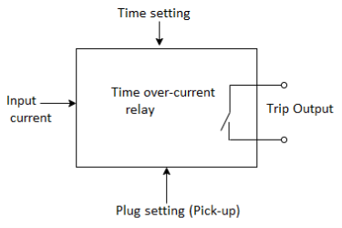
Block diagram of an over-current relay
The plug-setting multiplier, PSM, is defined as follows: PSM = 
Where Irelay is the current through the relay operating coil and PS is the plug-setting of the relay. The value of PSM tells us about the severity of the current as seen by the relay. A PSM less than 1 means that normal load current is flowing. At PSM > 1, the relay is supposed to pick up. Higher values of PSM indicate how serious the fault is.
Types of Over Current Relays
(i) Instantaneous Over Current Relay
Construction and working principle of instantaneous over current relay is quite simple.
Here generally a magnetic core is wound by a current coil. A piece of iron is so fitted by hinge support and restraining spring in the relay, that when there is not sufficient current in the coil, the NO contacts remain open. When the current in the coil crosses a preset value, the attractive force becomes enough to pull the iron piece towards the magnetic core, and consequently, the no contacts get closed.
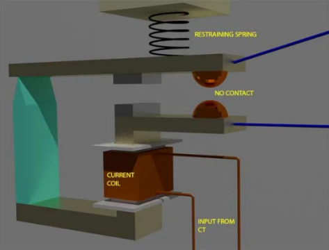
We refer the pre-set value of current in the relay coil as pickup setting current. This relay is referred as instantaneous over current relay, as ideally, the relay operates as soon as the current in the coil gets higher than pick upsetting current. There is no intentional time delay applied. But there is always an inherent time delay which we cannot avoid practically. In practice, the operating time of an instantaneous relay is of the order of a few milliseconds.
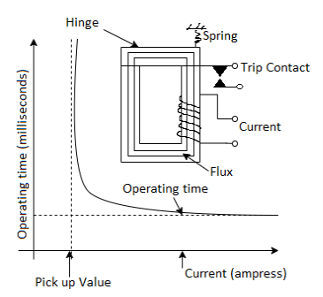
Figure- Instantaneous over-current relay characteristic
(ii) Definite Time Over Current Relay
This relay is created by applying intentional time delay after crossing pick up the value of the current. A definite time overcurrent relay can be adjusted to issue a trip output at an exact amount of time after it picks up. Thus, it has a time setting adjustment and pickup adjustment.
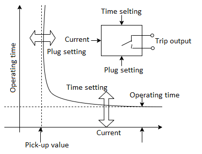
Figure- Definite time over-current relay characteristic
(iii) Inverse Time Over Current Relay
Inverse time is a natural character of any induction type rotating device. Here, the speed of rotation of rotating part of the device is faster if the input current is more. In other words, time of operation inversely varies with input current. This natural characteristic of electromechanical induction disc relay is very suitable for overcurrent protection. If the fault is severe, it will clear the fault faster. Although time inverse characteristic is inherent to electromechanical induction disc relay, the same characteristic can be achieved in microprocessor- based relay also by proper programming.
(iv) Inverse definite minimum time (IDMT) Over Current Relay
This is possibly the most widely used characteristic. The characteristic is inverse in the initial part, which tends to a definite minimum operating time as the current becomes very high. The reason for the operating time becoming definite minimum, at high values of current, is that in the electromechanical relays the flux saturates at high values of current and the relay operating torque, which is proportional to the square of the flux, does not increase substantially after the saturation sets in. Such a characteristic came about because of the limitation of the electromechanical technology. Ideally, we may demand that the operating time be inverse in nature throughout the operating range. The mathematical relation between the current and the operating time of IDMT characteristic can be written as:

Where PSM is the plug-setting multiplier and TMS is the time-multiplier setting of the
Relay. Thus, the operating time is directly proportional to the TMS and inversely proportional to the PSM.
Very inverse time over-current relay
The inverseness of this characteristic is higher than that of the IDMT characteristic. The mathematical relation between the current and the operating time of such a characteristic can be written as:

Extremely inverse time over-current relay
The inverseness of this characteristic is higher than that of the very inverse characteristic. The mathematical relation between the current and the operation-g time of such a characteristic can he written as:

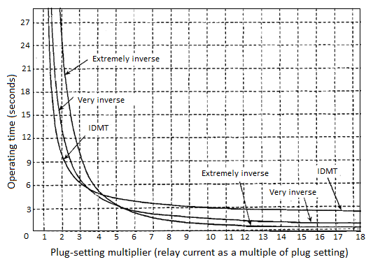
Figure- Inverse definite minimum time relay characteristics (TMS = 1.0)
Application of Definite Time OC Relays for Protection of a Distribution Feeder
Let us consider a three-phase feeder given in the figure below, with two line sections AB and BC. DTOC relays are used at buses A and B. There are loads at all the three buses.
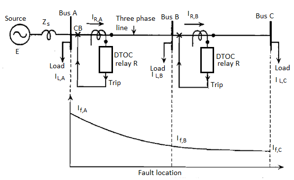
Figure: Application of DTOC relays for feeder protection
The objective here is to set the DTOC relays at buses A and B so that the so that the entire feeder gets over-current protection arranged as primary and back-up protection.
The first step in designing the over-current protection is to select the ratios for all the CTs. The secondary current of the CT is decided by the rating of the relay current coil. The CT primary current is decided by the maximum load current to be carried by the CT primary.
Next step is to determine the relay setting. This means to select the pick up value of the relay and to set the operating time of relay.
While setting the pick-up value of the relay, it should be kept in mind that the relay should allow normal load as well as a certain degree of overload to be supplied. Thus the pick-up value of the relay should be more than the allowable maximum load. At the same time, the relay should be sensitive enough to respond to the smallest fault. Thus, the pick-up value should be less than the smallest fault current. Therefore:

For the operating time of the relay, we must follow the principle that a relay must get an adequate chance to protect the zone under its primary protection. Only if the primary protection does not clear the fault, the back-up protection should initiate tripping. Thus, as soon as the fault takes place, it is sensed by both the primary and the back-up protection.
The primary protection is the first to operate, its operating time being less than that of the back-up relay. We have to allow for the overshoot of the primary relay, so that there is proper coordination between the primary and the back-up.
Overshoot time is defined as the time for which the relay mechanism continues to move, even after the operating coil has been de-energized. Overshoot is because of the moment of inertia of the moving system.
The correct procedure would be to start the setting from the tail end of the feeder system. The relay, which is at the end of the radial feeder, can be made to operate without any delay, as it does not have to coordinate with any other relay. Let us assume that the operating time of RB is set to 0.1s. Thus relay RA should wait for 0.1s plus, a time equal to the operating time of circuit at bus B (TCB,B) plus overshoot time of relay A (Tos,A). Thus:


Assuming CB operating time = 0.5 s and overshoot time = 0.2 s, we have:

The time step between the operating times of the two relays, which is equal to the sum of the operating time of the circuit breaker at B and the overshoot time of relay A, is essential for maintaining selectivity between relays at A and B. Hence this interval is referred to as the selective time interval (STI).
Relay | Purpose | Pick-up value | Time setting |
 | Primary protection of section BC. Note:  |  | Fastest  |
 | Back-up protection of section BC Primary protection of section AB |
 |    |
Note that the setting process has to be started from the relay which is at the tail end of the system. This is because this relay is not at all constrained by selectivity problems. All other upstream relay settings are tied up with their downstream neighbors.
It can be seen from this figure that as the fault moves towards the source, the fault currents become larger and the fault clearing time also becomes longer. This is because the relays nearer the source are deliberately delayed so that they are selective with relays downstream Thus, the relay nearest to the source is the slowest. This is not desirable.
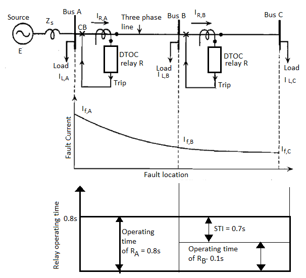
Figure- Setting of DTOC relays for OC protection of a feeder
Application of Inverse Definite Minimum The Relay on a Distribution Feeder
Consider a radial feeder with two buses A and B where IDMT OC relays are to be used. It should be noted that:

Bus A | Bus B | Bus C |
 |  |  |
 |  |  |
Figure - Setting of IDMT OC relays
The purpose of relay RB is to provide primary protection to line BC. The purpose of relay RA is to provide primary protection to line AB and back-up to line BC.
The setting process is started from the tail end of the system:
(a) Deciding the CT ratios and plug settings:
- At relay B, the maximum load current, assuming 25% overload is:
80 A + (0.25 x 80 A) = 100 A
- Assuming 1 A relay to be used, the CT ratio can be selected to be 100 : 1. The plug setting PS can be done at l00%, i.e. PS = 1.0 A.
(b) At relay A the maximum load current, assuming 25% overload is:

Assuming 1 A relay to be used, the CT ratio can be selected to be 300 : 1. The plug setting can be done at l00%, i.e. PS = 1.0 A.
(b) deciding the time-multiplier settings: Starting from the most remote relay 
(i) Since  does not have to maintain selectivity with any other relay, it can be made to operate the fastest. Thus the TMS of
  can be selected as 0.1
(ii) Now to maintain selectivity between  and
and  , the following constraint must be met:

The operating time of  for maximum fault just beyond bus B can be found from

For maximum fault at B, fault current=3000A on primary side which becomes (3000/100)=30A secondary. Since plug setting is done at 1.0 A,

The TMS of  has alread been set at 0.1. Substituting these values, we get

Let  . Then

This value of 0.7s is the desired operating time of  Assuming overshoot time of
  to be 10% of 0.7s ie
Thus we get the required operating time of  for maximum fault at bus B

The TMS of  can be found from the following expression for the operating time of
We have for  for the above condition

This finishes the setting of both the relays.
We can verify that the selectivity for minimum fault at bus B is automatically maintained.
Minimum fault current for fault at bus B=2000 A. Relay B current corresponding to this is 2000/100=20 A. Since plug setting is 1 A, this translates into PM of 20. For relay  TMS-0.1. Thus operating tme of
  for minimum fault at bus B will be


Expected operating time of  for this fault should be greater than
0.226+0.5+0.1(0.226+0.5)=0.726+0.0726=0.7986=0.8 s (approx.)
Now let us find out the actual operating time of  for minimum fault at bus B:
Minimum fault current=2000 A
Really  current corresponding to this is 2000/300=6.66A
Since plug setting is 1 A, this translates into a PSM of 6.66. For relay 
 Thus the operating time of
  for minimum fault at bus B will be:

This value of 0.94 s is greater than the minimum operating time of 0.8 s, required for maintaining selectivity  and
and 
The results can be listed as follows:
Relay CT ratio Plug setting TMS
 100:1 1 A 0.1
 300:1 1 A 0.26
The following general rules can be deduced from the above setting exercise:
- Start the setting from the relay at the tail end of the system.
- Plug setting should be such that:
 i.e. for plug setting consider minimum fault current at the end of the next section.
 - TMS should be decided such that the selectivity with the next relay downstream is maintained for maximum fault current at the beginning of the next section.
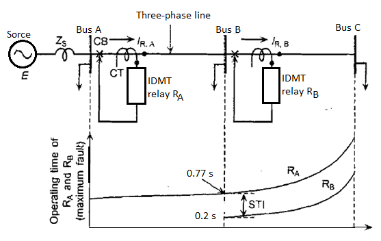
Figure- Variation of fault current against fault location for IDMT relays under maximum fault condition
Choice between IDMT and DTOC Relays
It can be seen that IDMT relays offer significant improvement in fault clearing times over DTOC relays. However, there are situations where IDMT relays do not offer
Significant advantages over DTOC relays.
For example, consider a system where Zs >> ZL. Since the fault current as a function of fault location is proportional to

It would remain more or less constant throughout the length of the feeder, therefore, the inverseness of the IDMT characteristics cannot be exploited. In such situations, DTOC relays being cheaper may be preferred. Such feeders are also described as electrically short in length, irrespective of their physical length. Thus we can say that DTOC relays are suitable for lines which are short in length.
It is a practice to recommend DTOC relays when 
References:
1. J. L. Blackburn, “Protective Relaying: Principles and Applications”, Marcel Dekker, New York, 1987.
2. Y.G. Paithankar and S. R. Bhide, “Fundamentals of power system protection”, Prentice Hall, India, 2010.
3. A.G. Phadke and J. S. Thorp, “Computer Relaying for Power Systems”, John Wiley & Sons, 1988.
4. A.G. Phadke and J. S. Thorp, “Synchronized Phasor Measurements and their Applications”, Springer, 2008.
5. D. Reimert, “Protective Relaying for Power Generation Systems”, Taylor and Francis, 2006.