Unit - 3
Equipment Protection Schemes
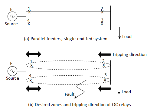
There are situations where it becomes necessary to use directional relays to supervise OC relays. One such situation is a single-end-fed system of parallel feeders, as shown in the figure below, where a fault on any of the parallel lines is fed not only from the faulted line but from the healthy line as well.
If directional relays are not provided, in conjunction with OC relays, then the desired
Zones will not be generated. This will result in both lines being tripped out for any fault on any one of the lines.
It may be noted that directional relays with tripping direction away from the bus will be required at locations '2' and '3'. However, at locations '1' and '4', non-directional over-current relays will suffice. Since directional relay units cost more and also need the provision of PTs, they should be used only when absolutely necessary.
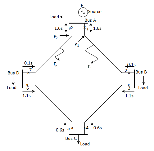
Ring main feeder system is another situation where directional supervision of OC relays is required. It is well known that the ring main feeder allows supply to be maintained to all the loads in spite of fault on any section of the feeder. A fault in any section causes only the CBs associated with that section to trip out, and because of the ring topology, power flows from the alternate path.
Characteristics of directional relay
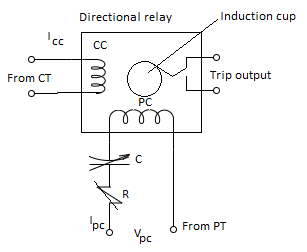
A directional relay can be compared to a contact making wattmeter. A wattmeter develops maximum positive torque when the current and voltage supplied to the current coil and the pressure coil are in phase. If we define the maximum torque angle (MTA) as the angle between the voltage and current at which the relay develops maximum torque, then a wattmeter can be called a directional relay with MTA of zero degree.
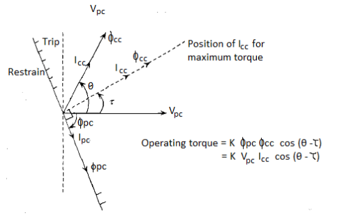
The phasor diagram for a directional relay is depicted above:
VPC is the voltage applied to the pressure coil. The current drawn by the pressure coil IPC lags the voltage by a large angle  .
.
As the fault moves from the forward to the reverse direction, the current undergoes, a large change in its phase whereas the phase of the voltage does not change substantially. Thus, voltage signal is the reference against which the phase angle of the current is measured.
Now, in a relay based on induction principle, the two fluxes responsible for torque production,  and
and  should be shifted in phase by 90°, for them to produce maximum torque. The torque becomes zero when the current phasor is
  away from the MTA position. This gives the direction of the current phasor for maximum torque, the maximum torque angle
  , and the boundary between tripping and restraining regions on the phasor diagram.
The operating torque of the directional relay can be expressed as:
Operating torque 
From phasor diagram it can be seen that:


Since  and
and 

From the phasor diagram, it can be easily seen that the maximum torque angle is given by

Since the pressure coil is highly inductive, the value of  is of the order of
  to
to  . This gives MTA of
  to
to  . However
  and hence can be adjusted to any desired value if an external resistance of capacitance is introduce into the pressure coil circuit.
Consider a transmission line AB as shown in the figure below. Let us assume that there is source only at end A. We wish to generate a zone of protection which extends from A to B. Assume that the proposed relay is located at end A, where the local current and voltage are available through a CT and a PT, whose ratios have been assumed as 1:1 for the sake of simplicity. The reach of the distance relay is thus made equal to Zset.
The line is modelled as a series R-L circuit for the purpose of relaying without much loss of accuracy.
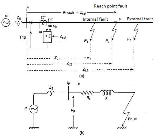
Consider three faults: an internal fault Fl, an external fault F3, and a fault at reach point fault F2. Now, let us compare the relay voltage VR with the product of relay current IR and Zset for all the three faults.
Fault | Current at relay location,  | Voltage at relay location,  | Compare  | Desired response of relay |
 |  |  |  | Restrain |
 |  |  |  | Verge of operation |
 |  |  |  | Trip |
The trip law that emerges is:
If  then trip;
Else restrain
This can be written as:
If  ;
;
Else restrain
However, the ratio  is the magnitude of the apparent impedance
  as seen by the relay, therefore, the trip law can be written as
If  then trip;
Else restrain
The relay, therefore, somehow, has to compute the impedance as seen from its location and compare it with set value to take the trip decision. Because of the simple series model of the faulted line, the line impedance is directly proportional to the distance to fault. Hence the name distance relay. This relay is also called as impedance relay.
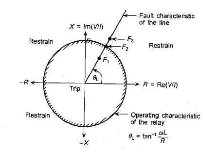
Figure - Characteristics of simple impedance relay on R-X plane with fault characteristic of the line superimposed.
A differential relay is the relay which operates when the phasor difference of two or more similar electrical quantities exceeds a predetermined value.
In static differential relay, two similar quantities either voltages or currents are compared. The comparator measures the vector difference between the two similar input signals. The rectifier bridge type comparator is generally used in the static differential relay. The block diagram is shown in the figure

In normal conditions, the two quantities balance each other and the comparator output is zero and the relay us inoperative.
For any internal fault conditions, the comparator senses the phase difference between the two quantities and produces the output. This is amplified and given to the trip circuit which operates the relay. This scheme is used for protection of the generators and transformers against any type of internal fault.
The various advantages of static differential relay over electromagnetic differential relay are, highly sensitive, compact, and very fast in operation, low power consumption, less burden on input CTs and inrush current proof characteristics.
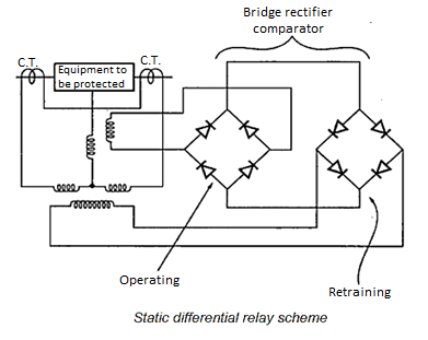
The basic static differential relay scheme is shown in the above figure.
Let no and nr be the number of turns of operating and restraining coils respectively. Then the relay operates when,
K1 no Io > K2 nr Ir + K'
Where k1 and k2 are design constants while K' is the spring control torque.
Nature of Transformer Faults
Power Transformers generally develop rare faults as it is static, totally enclosed and oil immersed but if these faults sustain the results may be serious unless the transformer is disconnected. The faults that generally occur in the transformer can be divided as:
1. Faults in auxiliary equipment which is a part of the transformer
2. Faults in the transformer winding and connections
3. Overloads and external short circuits.
Faults in Auxiliary Equipment
The detection of faults in auxiliary equipment is necessary to prevent ultimate failure of the main transformer windings. In these the components are
(i) Transformer oil: Oil is used as an insulator in transformer. So, when low oil is present the live parts and the bushing leads gets exposed which are supposed to be beneath the oil. Oil level can be determined by the means of alarm indicators for immediate attention.
(ii) Gas cushion: The presence of oxygen or moisture may lead to deterioration of the transformer oil. Hence, exclusion of this presence is necessary. Since the operating pressure varies within the tank, hence sealing of the tank is not an option. Pressure indicators and conservators are used to counter the expansion and contraction of oil. Whereas silica gel is provided in the breathing vent to absorb the moisture content. Sometimes a nitrogen cylinder is provided to provide an inert atmosphere maintaining the pressure between 0.5 and 0.8 atm.
(iii) Oil pumps and forced air fans: The top oil temperature normally gives the indication of the load on the transformer. A rise in temperature would indicate an overloading situation or due to the fault in cooling system. A thermometer with alarm contacts will indicate the temperature rise in oil due to any of these faults.
(iv) Core and winding insulations: These faults can turn into major faults if not taken care of. Insulation failures may develop if
- The insulation of the laminations and core bolts may be of poor quality.
- Poor quality of insulation between windings or between winding and the core.
- Badly made joints or connections.
Winding Faults Electrical Faults that can cause immediate serious damage and are determined by the presence of unbalanced current or voltage may be divided into following classes:
(i) Faults between adjacent turns or parts of coils such as phase-to-phase faults on the HV and LV external terminals or on the winding itself or short circuits between turns of HV and LV windings.
(ii) Faults to ground or across complete windings such as phase-to-earth faults on either HV or LV side.
A short circuit between turns can start with a point contact resulting from mechanical forces or insulation deterioration due to excessive overload. The puncture of the turn insulation would cause a path through which the normal frequency voltage can maintain an arc. But if the voltage is insufficient to maintain the arc, it would be quenched by the oil present.
In the second case, the ground faults are easy to detect as they are characterized by emission of large amount of gas due to decomposition of oil as well as in large values of fault currents. Rapid clearance is necessary to avoid excessive damage and to maintain stability.
Overload and External Short Circuits
Overloads can be persistent in the system provided the temperature rise in the windings is within the limits. Excessive overloading can cause deterioration in insulation and subsequent failure. An alarm indication can be initiated when the temperature limits exceed. External short circuits may only be limited by the transformer reactance, so a low value would result in excessive fault currents.
Differential Protection of Transformers
The best way of protection of any apparatus against an internal fault is by the method of differential protection scheme since it covers the apparatus’ zone of protection. Therefore, for a transformer having ratings of 5 MVA and above, the differential scheme serves as an important protection against internal phase-to-phase and phase-to-earth faults. Any fault in the protected part would result in the deviation of the current intensities at the input and output. Hence, the result of this unbalanced current can be employed for the tripping of the relay. For this reason, the differential scheme combines the characteristics of selectivity and highest tripping time of the relay. A particular differential scheme is given below for a three-phase star delta transformer.
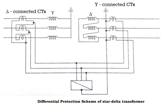
For the relay to detect 0 spill current in normal operation, the currents incoming from both the CTs should be in direct opposition. Since in a star delta transformer the line currents have a displacement of 30˚, so the CTs have to be connected in delta on the star side of the transformer and in star for the delta side to avoid any spill current through relay in normal operation. Another advantage of this connection is the avoiding of triplet harmonics to appear on the line currents due to delta windings.
Over-current Protection
Figure below shows two numbers of phase-fault over-current relays and one ground-fault over-current relay for providing over-current protection to the star-delta transformer. Such a scheme may serve the purpose of providing either the primary protection for smaller transformers or the back-up protection for bigger transformers.
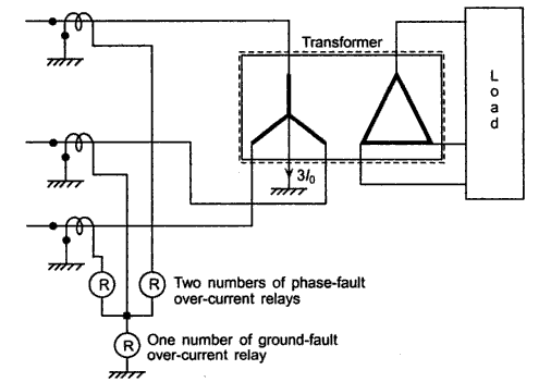
Figure- Over-current protection of a transformer
The pick-up value of the phase-fault over-current units is set such that they do not pick up on maximum permissible overload, but are sensitive enough to pick up on the smallest phase fault. The pick-up of the earth fault relay, on the other hand, is independent of the loading of the transformer. The neutral current under load conditions is quite small. The neutral current is essentially because of load unbalance. It is interesting to note that the third harmonic currents, in particular and triple-n harmonics (harmonics of order 3, 6, 9, ...) in general, which arise due to distortions introduced by electronic loads, also end up as zero sequence currents and flow through the neutral.
The generator is the prime equipment in the power system. The increased size of the generators and even greater increase in their capacity makes the imperative to protect them against fault. Unlike other apparatus only isolating the circuit breaker is not enough to prevent further damage as the generator would still supply power to its stator windings until the excitation is suppressed. So, for isolation it is needed to open the field to avoid any excitation, and to stop the fuel supply to the prime mover.
(a) Stator faults: These include the following
- Phase to earth faults.
- Phase to phase faults
- Inter turn faults.
The stator is prone to maximum amount of faults in the system with phase to earth fault being the most common. The inter turn faults and phase faults are less common but develop into an earth fault in the long run.
(b) Rotor faults: The faults that exist in the rotor can be either earth fault or an inter turn fault. These faults are mainly caused by the mechanical and thermal stress acting upon the winding insulation. The existence of such fault may be taken care of as the incidence of second fault may short circuit some part of the field winding which would result in the asymmetrical air gap flux which may cause vibrations and result in damage to the bearings. In the modern era, the practice is to operate the field winding isolated from the earth so that a single fault between field winding and rotor body due to insulation breakdown can be tolerated.
(c) Abnormal running conditions: The abnormal running conditions that can occur are: (i) loss of excitation
- Unbalance loading
- Overloading
- Failure of prime mover
- Over speeding
- Over-voltage.
Field failure may occur due to a faulty field breaker. When a generator loses its excitation, the amount of reactive power supplied to the system is lost. Instead, it would draw excitation from the system while delivering real power at leading power factor. This leads to an operation of an induction generator where the speed is slightly increased. Also due to loss of excitation there would be a voltage fall which would lead to loss of synchronism. The situation may also lead to overheating in rotor and damper windings.
If there is any unbalance in the system due to a phase fault or due to the unbalance loading, it gives rise to negative sequence currents. It produces an armature reaction field which rotates in a direction opposite to that of the rotor and hence produces a flux which is twice the frequency. These currents are linked to the rotor and damper windings which produces heating in the windings.
When there is an overloading in the generator, it would draw more current and as a result would produce more heating loss in the stator which may damage the insulation. When there is a failure of prime mover, the real power delivering capacity is lost and instead it would draw power from the system making it to run as a motor. This affects the drive of the system due to opposite torque being applied on to the shaft.
When a sudden load is removed then according to the AGC control, the machine is going to over speed. This happens mainly in the hydraulic generators since the water flow cannot be immediately stopped for the inertia in water motion. Over voltages may occur due to the failure in the AVR control in the excitation or may be due to over speeding.
Stator Protection
The most common fault that happens in stator is the earth faults. Since an earth fault near the generator is very critical as the magnitude of the current is very high, so the current is limited by either a resistance connected in the neutral circuit. Depending on this value the current can be limited to either 200 to 250 A which is done by resistor earthing or 4 to 10 A by distribution transformer earthing. Even though the second method has an advantage of reducing the damage on to the stator core, the practicability of this method is limited if the transformer is connected in delta.
In the resistor earthing, the resistance is connected between the neutral and the ground and the CT is mounted on the neutral with an IDMT or an instantaneous attracted armature type relay. The maximum value of resistance is given by

If the neutral is earthed through the primary winding of a distribution transformer, earth-fault protection is provided by connecting an over-voltage relay across its secondary, then the maximum value of resistance is equal to

Where N is the turn ratio of the transformer.
Generator differential protection:
The best form of protection for the stator windings against all the internal faults is by the use of differential protection. The relay recommended for this application is instantaneous attracted armature type which is immune to ac transients and has the high-speed feature if the CTs are reasonably matched. But when the CTs have dissimilar characteristics, biased differential relay can be applied as it would result in high amount of spill current flowing through the relay.
A particular longitudinal biased differential relay protection scheme for the generator is given as below-
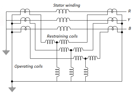
Stator Inter turn fault protection
An inter-turn fault occurring on the same phase of the stator winding do not disturb the neutral current, hence by the use of longitudinal differential relay it is not possible to detect such type of fault. This results to another modification in the protection designing whereby we make the transverse differential relay in case of the generators where the stators have two windings per phase. The protection scheme is given as
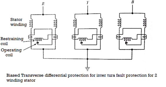
Rotor Protection
The rotor windings as discussed earlier may be due to earth faults or open circuits. The figure shows a modern method of rotor earth fault detection. The field is biased by a dc voltage which causes current to flow through R for an earth fault.
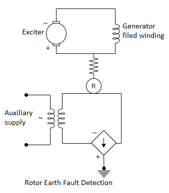
Loss of Excitation (Field Failure) Protection
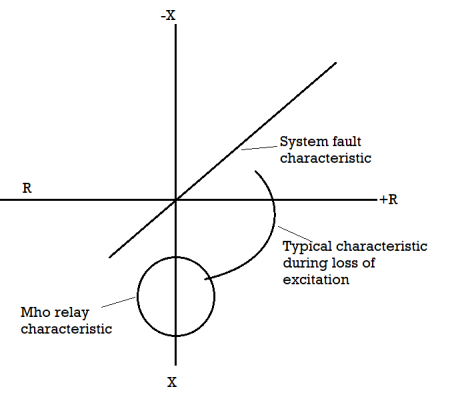
The loss of field circuit imposes the circuit to draw reactive VAR from the system. This results in machine being operated as an induction generator. This causes overheating in the circuit. Loss of excitation is detected by the import of VAR indicating either actual or prospective loss of synchronism. So, the transients in such phenomena can be allowed for 1 to 5 seconds in tripping sequence of the relay. Due to the loss of excitation, there would be a drop in voltage and resulting in the drop of current. This can be detected by an undercurrent moving coil relay in the field circuit. Even this method is not suitable for generators having wide range of operation in the field excitation. The alternative solution that can be implemented is to apply an offset impedance or mho relay. Its operating characteristics are arranged so that during conditions of low excitation the effective generator impedance falls in the tripping zone.
The faults in the bus zone can be divided as follows:
(i) Failure of circuit breaker to interrupt fault current or failure to clear under through fault conditions.
(ii) Insulation failure due to material deterioration.
(iii) Flashover causes by prolonged and excessive over voltages.
(iv) Errors in the operation and maintenance of switchgears.
(v) Foreign objects accidentally falling across bus bars
Bus Backup Protection
When no separate protection is provided for the bus bars but there is a provision of distance protection, so any fault that is occurring at the bus zone protection would come under the zone 2 protection of the distance relay where it covers the bus bar and the next line also. This is satisfactory for the small switchgear case but not in the case of prime installations. Therefore, a separate bus zone protection may be provided for the same.
Differential Scheme of Bus Bar Protection
It is based on the simple circulating current principle that during the normal condition or external fault condition, the incoming current must be equal to the leaving current. Since the bus in a power system acts as a node in an electrical circuit, if the summation of currents is not equal to zero, it means that there is a short circuit due to ground fault or phase to phase fault. The differential scheme can be given as below, whose CT ratio are given according to the highest current that is flowing in the feeder circuits.
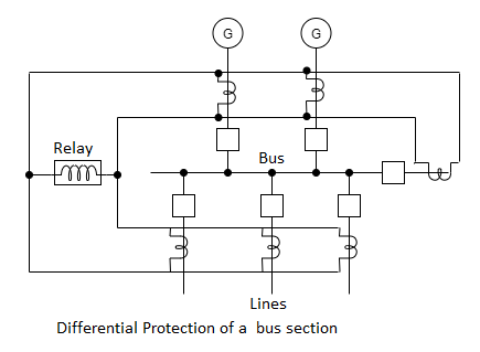
Since the CTs used here are of the same ratio, when there is a through fault condition, the magnetic conditions of the iron cored CTs would result in false operation due to saturation. Even with biasing of the relay, the improvement is not satisfactory. An improvement can be done by the use of non-iron cored CT also known as linear coupler to overcome the difficulties of iron cored CTs. In this the secondary voltage is proportional to the primary current. So, when there is an external fault, the addition of the voltages won’t result to zero since the current is still balanced, but when there is an internal fault there is an unbalance in current and hence results to some voltage in the linear coupler scheme.
Frame Leakage Protection
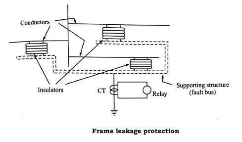
It is possible to design a station so that the faults which develop are mostly earth faults, by providing earthed metal barrier surrounding each conductor in the bus structure. With this arrangement every fault that might occur must involve a connection between the conductor and an earthed metal part. The figure below shows the metal supporting structure also known as a fault bus earthed through a CT. Sometimes, the structure is earthed by the means of impedance connected in the neutral.
In the resistance earthed neutral, the advantage is that besides limiting the value of current it is also used to protect certain part of the generator or transformer windings which are connected in the feeder circuits. The earth fault current for protecting x% of the winding is given as

This must be also the primary fault setting of the differential protection IS for minimum operating current.

Or % winding unprotected is

There are 8 types of bus bar arrangements
Type 1: Single Bus-Bar Arrangement
This is the simplest arrangement consisting of a single set of bus-bars for the full length of the switchboard and to this set of bus-bars are connected all the generators, transformers and feeders.
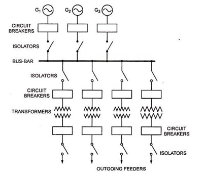
Each generator and feeder are controlled by a circuit breaker. The isolators permit isolation of generators, feeders and circuit breakers from the bus-bars for maintenance. The chief advantages of such a bus-bar arrangement are low initial cost, less maintenance and simple operation.
The glaring drawback of this system is that in case of fault on the bus-bars, whole of the supply is affected and all the healthy feeders are disconnected. Moreover, when maintenance is to be carried out on any of the feeder sections or on a part of bus-bar the whole supply is to be disrupted. Thus, such an arrangement provides least flexibility and immunity from total shutdown.
Such bus-bar arrangement is employed for switchboards, small and medium sized substations, small power stations and dc stations.
Type 2 - Single Bus-Bar Arrangement with Bus Sectionalization:
The bus-bar may be sectionalized by a circuit breaker and isolating switches so that a fault on one part does not cause a complete shutdown. In large generating stations, where several units are installed, it is a common practice to sectionalize the bus.
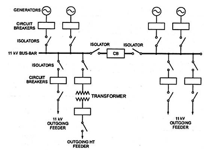
Normally the number of sections of a bus-bar are 2 to 3 in a substation, but actually it is limited by the short-circuit current to be handled. In a sectionalized bus-bar arrangement only one additional circuit breaker is required which does not cost much in comparison to the total cost of the bus-bar system.
Such an arrangement provides three main advantages over simple single bus-bar arrangement:
Firstly, in the event of occurrence of fault on any section of the bus-bar, the faulty section can be isolated without affecting the supply of other section or sections.
Secondly, one section can be completely shut-down for maintenance and repairs without affecting the supply of the other section (s).
Thirdly, by adding a current limiting reactor between the sections the fault level (MVA) can be reduced thereby circuit breakers of lower capacity can be used.
At times air-break isolators were used in place of circuit breakers as bus-sectionalizer due to economy, but it must be remembered that any isolation affected by them must be affected under off-load conditions otherwise it may cause spark. It will be preferable to provide circuit breaker as a sectionalizing switch so that uncoupling of bus-bar may be carried out safely during load transfer. A double isolation is however necessary when the circuit breaker is employed as sectionalizing switch so that the maintenance work can be carried out on circuit breaker while the bus-bars are alive.
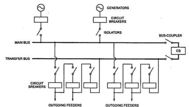
Type 3 Main and Transfer Bus Arrangement:
This arrangement has been quite frequently adopted where the loads and continuity of supply justify additional costs. This arrangement provides additional flexibility, continuity of supply and allows periodic maintenance without total shutdown. Such an arrangement is suitable for highly interconnected power network in which flexibility is very important.
Such an arrangement consists of two bus-bars, known as main bus-bar and transfer bus-bar used as an auxiliary bus-bar. Each generator and feeder may be connected to either bus-bar with the help of bus coupler which consists of a circuit breaker and isolating switches. In this arrangement a bus coupler is usually used so that change-over from one bus-bar to the other can be carried out under load conditions.
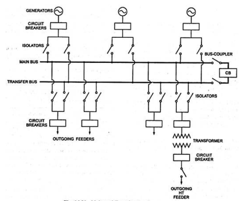
The advantages and disadvantages of the arrangement are gives below:
Advantages:
i. It ensures continuity of supply in case of bus fault. In the event of occurrence of fault on one of the bus, the entire load can be transferred to the other bus.
Ii. Repair and maintenance can be carried out on the main bus without interrupting the supply as the entire load can be transferred to the auxiliary bus.
Iii. Each load can be supplied from either bus.
Iv. The in-feed and load circuit may be divided into two separate groups if required from operational considerations.
v. The testing and maintenance of feeder circuit breakers can be done by putting them on spare bus, thus keeping the main bus undisturbed.
Vi. The maintenance cost of substation is lowered.
Vii. The bus potential can be used for relays.
Disadvantages:
i. Additional costs.
Ii. The bus is maintained or expanded by transferring all of the circuits to the auxiliary bus depending upon the remote backup relays and breakers for removing faults of the circuits. During this condition a line fault on any of the circuits of the bus would shut-down the entire station.
Type 4 Double Bus Double Breaker Arrangement:
In very important power stations two circuit breakers are employed for each circuit. Such a bus-bar arrangement does not require any bus-coupler and permits switch-over from one bus to the other whenever desired, without interruption. This bus arrangement is very costly and its maintenance cost is also high.
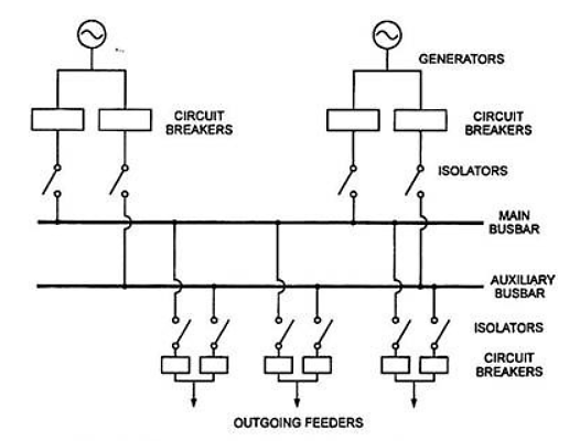
This arrangement provides maximum flexibility and reliability as the faults and maintenance interrupt the supply to the minimum. A circuit breaker can be opened for repairs and usual checks and the load can be shifted on the other circuit breaker easily. But because of its higher cost, this arrangement is seldom used at the substations.
For 400 kV switchyards two main buses plus one transfer bus scheme is preferred. The transfer bus is used for transferring power from main bus 1 to main bus 2 and vice versa.
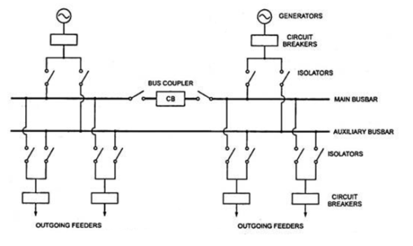
Type 5 Sectionalized Double Bus Arrangement:
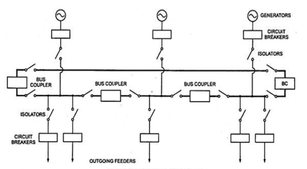
In this arrangement duplicate bus-bars are used with the main bus-bar in sections connected through a bus-coupler. In this arrangement, any section of bus-bar can be isolated for maintenance, while any section may be synchronized with any other through the auxiliary bus-bar. Sectionalization of auxiliary bus-bar is not required and would increase the cost if done.
Type 6 One-and-a-Half Breaker Arrangement:
This is an improvement over double bus double breaker arrangement and it affects saving in the number of circuit breakers. This arrangement needs three circuit breakers for two circuits. The number of circuit breakers per circuit comes out to be 1½ hence the name. This arrangement is preferred in important large stations where power handled per circuit is large.
This arrangement provides high security against loss of supply as a fault in a bus or in a breaker will not interrupt the supply. Possibility of addition of circuits to the system is another advantage. The bus potential can be used as supply to relays, however, at the time of bus fault such potential to the relay should be thrown off.
The main drawback of this arrangement is complications in relaying system because at the time of fault two breakers are to be opened. The other drawback is that for maintenance of circuit breakers if the load shedding is not used, two breakers are to be opened in which case the other circuit in the line-up will be operating with one breaker from one bus only. At the time of fault in that bus supply to the other circuit is also interrupted. The maintenance cost is higher.
The above arrangement has been used in important 400 kV and 750 kV substations.
Type 7 Ring Main Arrangement:
This is an extension of the sectionalized bus-bar arrangement where the ends of the busbars are returned upon themselves to form a ring. This arrangement provides greater flexibility as each feeder is supplied by two paths, so that the failure of a section does not cause any interruption of the supply. The effect of fault in one section is localized to that section alone.
The rest of the sections continue to operate. Circuit breakers can be maintained without interrupting the supply. The cost is also not much as the numbers of breakers used are nearly the same as that of a single bus-bar system.
The drawbacks of the system are:
(i) Difficulties in addition of any new circuit in the ring.
(ii) Possibility of overloading of the circuits on opening of any section of the breaker and
(iii) Necessity of supplying potential to relays separately to each of the circuit.
Type 8 Mesh Arrangement:
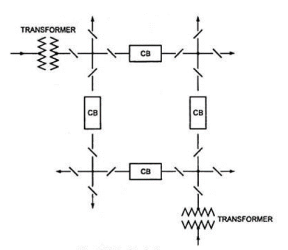
This is another arrangement making economical use of circuit breakers in a substation. In this bus-bar arrangement, the circuit breakers are installed in the mesh formed by the buses. The circuits are tapped from the node points of the mesh. Here, eight circuits are controlled by four circuit breakers.
When fault occurs on any section, two circuit breakers have to open, resulting in opening of the mesh. This arrangement provides security against bus-bar faults but lacks switching facility. It needs fewer circuit breakers than that required by one-and-a-half breaker arrangement. It is preferred for substations having large number of circuits.
References:
1. J.L. Blackburn, “Protective Relaying: Principles and Applications”, Marcel Dekker, New York, 1987.
2. Y.G. Paithankar and S. R. Bhide, “Fundamentals of power system protection”, Prentice Hall, India, 2010.
3. A.G. Phadke and J. S. Thorp, “Computer Relaying for Power Systems”, John Wiley & Sons, 1988.
4. A.G. Phadke and J. S. Thorp, “Synchronized Phasor Measurements and their Applications”, Springer, 2008.
5. D. Reimert, “Protective Relaying for Power Generation Systems”, Taylor and Francis, 2006.