Unit - 5
Modelling and Simulation of Protection Schemes
Current transformer (CT) is a bridge between the primary and secondary equipment in power system, utilized for transferring large currents proportionally to currents with small amplitudes for secondary measuring and monitoring equipment and relay protective equipment. In case of a short-circuit incident, as the power system capacity and the voltage level increase, the short-circuit current will reach tens of times or even hundreds of times of CT rated current, leading to CT saturation
In that situation, CT cannot transfer the primary current correctly, which causes mal-operation of protection equipment and greater errors of fault location equipment. In response to this, manufacturers open a small air gap on the core of CT, which is about one-thousandth of the total length of the magnetic circuit. The air-gapped CT can guarantee that the errors are within the permissible range of the relay protection in the steady state and the transient state.
Currently, there are large number of papers on the closed-core CT modeling. However, there are only a few studies have been accomplished on modeling air-gapped CT.
The air-gapped CT model is established on the PSCAD/EMTDC platform, where the real-time magnetization curve is generated by hysteresis loop compressing method, and the real-time excitation inductance is calculated by using the arc tangent function to fit the limiting hysteresis loop. This model can simulate the saturation characteristics of air-gapped CT, but the simulation of the core is not accurate enough.
Jiles-Atherton (JA) Theory. This model can accurately simulate the effect of air gap on the magnetization process. However, the parameters such as regional coupling coefficient, thermal coefficient, regional flexibility, direction coefficient, which are required for the JA theoretical model, are often hard to accurately obtained and can only be approximated.
Equivalent Circuit of CT
To begin with, equivalent circuit of a CT is not much different from that of a regular transformer (fig1). However, a fundamental difference is that while regular power transformers are excited by a voltage source, a current transformer has current source excitation. Primary winding of the CT is connected in series with the transmission line. The load on the secondary side is the relaying burden and the lead wire resistance.
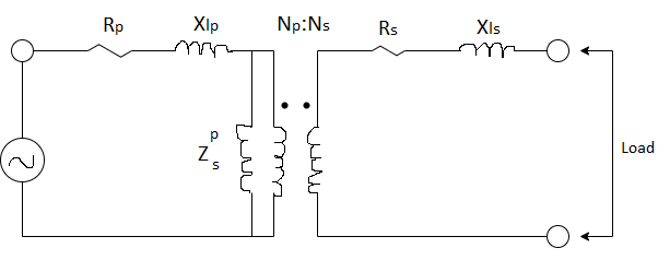
Figure1: Equivalent Circuit of CT
Total load in ohms that is introduced by CT in series with the transmission insignificant and line is hence, the connection of the CT does not alter current in the feeder or the power apparatus at all. Hence from modeling perspectives it is reasonable to assume that CT primary is connected to a current source. Therefore, the CT equivalent circuit will look as shown in fig 2. The remaining steps in modeling are as follows: As impedance in series with the current source can be neglected, we can neglect the primary winding resistance and leakage reactance in CT modeling.
For the convenience in analysis, we can shift the magnetizing impedance from the primary side to the secondary side of the ideal transformer.
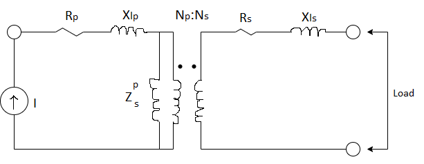
Figure 2: Modelling of a CT
After application of the above steps, the CT equivalent circuit is as shown in the Fig 3. The secondary winding resistance and leakage reactance is not neglected as it will affect the performance of CT. The total impedance on the secondary side is the sum of relay burden, resistance impedance and of lead wire leakage secondary winding. Therefore, the voltage developed in the secondary winding depends upon these parameters directly. The secondary voltage developed by the CT has to be monitored because as per the transformer emf equation, the flux level in the core depends upon it. The transformer emf equation is given by,
E2 = 4.44 fN2 m
Where  is the peak sinusoidal flux developed in the core. If
  corresponding to this flux is above the knee point, it is more or less obvious that the CT will saturate. During saturation, CT secondary winding cannot replicate the primary current accurately and hence, the performance of the CT deteriorates.
Thus, we conclude that in practice, while selecting a CT we should ascertain that it should not saturate on the sinusoidal currents that it would be subjected to.
Use of numerical relays due to their very small burden vis-a-vis solid state and electromechanical relays, improves the CT performance. CT is to be operated always in closed condition. If the CT is open circuited, all the current Ip/N, would flow through Xm. This will lead to the development of dangerously high level of voltage in secondary winding which can even burn out the CT.
The equivalent circuit of a CT can be further simplified by transferring the current source to the secondary side. Thus, the equivalent circuit of the CT is as shown in fig.
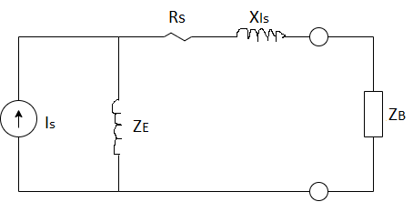
Figure 3: Final equivalent ZB circuit of CT
Equivalent circuit of Saturated CT
One of the major problems faced by the protection systems engineer is the saturation of CT on large ac currents and dc offset current present during the transient. When the CT is saturated, primary current source cannot be faithfully reflected to the secondary side. In other words, we can open circuit the current source in Fig. 4. Also, the magnetizing impedance falls down during saturation. Then the transformer behaves more like an air core device, with negligible coupling between the primary and secondary winding. The high reluctance due to the air path implies that the magnetizing impedance (inductance) falls down. The corresponding equivalent circuit is shown in fig. 5.
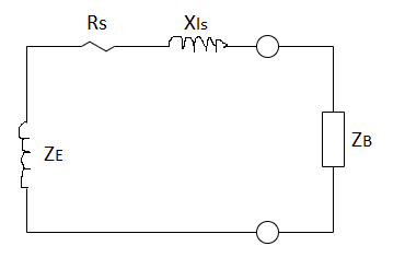
Figure – 4 CT equivalent circuit during saturation
Classifications of CT
The CTs can be classified into following types:
Measurement CTs
Protection CTs
A measurement grade CT has much lower VA capacity than a protection grade CT. A measurement CT has to be accurate over its complete range e.g. from 5% to 125% of normal current. In other words, its magnetizing impedance at low current levels. (and hence low flux levels) should be very high. Due to non-linear nature of B-H curve, magnetizing impedance is not constant but varies over the CT's operating range. It is not expected to give linear response (secondary current a scaled replica of the primary current) during large fault currents.
In contrast, for a protection grade CT, linear response is expected up to 20 times the rated current. Its performance has to be accurate in the range of normal currents and up to fault currents. Specifically, for protection grade CT's magnetizing impedance should be maintained to a large value in the range of the currents of the order of fault currents.
When a CT is used for both the purposes, it has to be of required accuracy class to satisfy both accuracy conditions of measurement CTs and protection CTs. In other words, it has to be accurate for both very small and very large values of current. Typically, CT secondary rated current is standardized to 1A or 5A (more common).
However, it would be unreasonable to assume that the linear response will be independent of the net burden on the CT secondary. For simplicity, we refer to the net impedance on the secondary side (neglecting magnetizing impedance) as the CT burden. It is quite obvious that the driving force E2 required to drive the primary current replica will increase as this burden increases. If this voltage exceeds the designer's set limits, then the CT core will saturate and hence linear response will be lost. Hence, when we say that a CT will give linear response up to 20 times the rated current, there is also an implicit constraint that the CT burden will be kept to a low value. In general, name-plate rating specifies a voltage limit on the secondary (e.g., 100 V) up to which linear response is expected. If the CT burden causes this voltage to be exceeded, CT saturation results.
IEEE Classification
ANSI/IEEE standards classify CTs into two types:
Class T CT
Class C CT
Class T CT’s
Typically, a class T CT is a wound type CT with one or more primary turns wound on a core. It is associated with high leakage flux in the core. Because of this, the only way to determine its performance is by test. In other words, standardized performance curves cannot be used with this types of CTs.
Figure 6 shows one such experimentally calibrated curve for a CT. The letter ‘B' indicates the burden in ohms to which the CT is subjected. It is seen that when burden is less than say 0.1 ohms, CT meets the linear performance criterion. However, as the burden increases to 0.5 ohms, the corresponding linearity criteria is not met till the end. At 4 ohms burden, there is significant deviation from the linear response.
A general rule of thumb is that, one should try to keep the CT burden as low as possible.
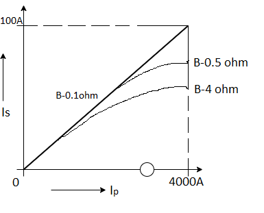
Fig 5
Ratio Error: CT performance is usually gauged from the ratio error. The ratio error is the percentage deviation in the current magnitude in the secondary from the desired value. In other words, if the current measured in the secondary is Is, true or actual value is Ip/N, where N is nominal ratio (e.g. N for a 100:5 CT is 20) and Ip is the primary current then ratio error is given by

When the CT is not saturated ratio error

Is a consequence of magnetizing current IE

Since
Therefore, % ratio error is equal to 
 .
.
When the CT is saturated, coupling between primary and secondary is reduced. Hence, large ratio errors are expected in saturation. The current in the secondary is also phase shifted. For measurement grade CTs, there are strict performance requirements on phase angle errors also. Error in phase angle measurement affects power factor calculation and ultimately real and reactive power measurements. It is expected that the ratio error for protection grade CTs will be maintained within  .
.
Class C CT’s
Letter designation 'C' indicates that the leakage flux is negligible. Class C CTs are the more accurate bar type CTs. In such CTs, the leakage flux from the core is kept very small. For such CTs, the performance can be evaluated from the standard exciting curves. In addition, the ratio error is maintained within  for standard operating conditions.
For such CTs, voltage rating on the secondary is specified up to which linear response is guaranteed. For example, a class C CT specification could be as follows: 200:5 C 100. The labeling scheme indicates that we are dealing with a 200:5 class C CT which will provide linear response up to 20 times rated current provided the burden on the secondary is kept below [100/(5 x 20) = 1] ohm. Similarly, a corresponding class T CT may be labeled as 200:5 T 100.
For class C CTs, standard chart for E2 versus excitation current (IE) on the secondary side is available. This provides the protection engineer data to do more exact calculations refer fig. 7 e.g., in determining relaying sensitivity.
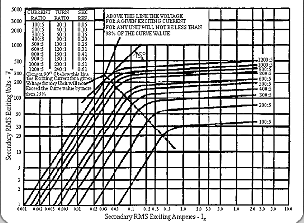
Figure 6
Potential transformers are also known as voltage step-down transformers or voltage transformers or instrument transformer, in which the voltage of a circuit is reduced to a lower voltage for measurement. The electromagnetic device used for the transformation of the higher voltage of the circuit to the lower voltage is called a potential transformer. The output of a low voltage circuit can be measured through voltmeters or wattmeters. These are capable of increasing or decreasing the voltage levels of a circuit, without a change in its frequency and windings. The working principle, construction of a potential transformer is similar to the power transformer and conventional transformer.
Potential Transformer Circuit Diagram
The potential transformer consists of primary winding with more turns and secondary winding with less number of turns. The high input AC voltage is given to the primary winding (or connected to the high voltage circuit to measure). The lower output voltage is taken across the secondary winding by using a voltmeter. The two windings are magnetically coupled to each other without any connection between them.
Construction of a Potential Transformer
Potential transformers are constructed with high quality to operate at low flux density, low magnetic current, and minimized load. When compared to a conventional transformer, it uses large conductors and an iron core. It can be designed in the form of a core type and shell type to ensure the highest accuracy. Usually, core type potential transformers are preferred to transform the high voltage to lower voltage.
It uses co-axial windings to reduce the leakage reactance. As the potential transformers are operated at high voltages, the high voltage primary winding is divided into small sections turns/coils to reduce the insulation cost and damage. The phase shift between an input voltage and output voltage should be monitored carefully to maintain a lower voltage by varying the load. Windings covered with vanish cambric and cotton tape to reduce the insulation cost.
Hard fiber separators are used to separate the coils. Oil-filled bushings are used to connect the high voltage potential transformers (above 7KV) to the main lines. The primary winding of a potential transformer has a large number of turns whereas secondary winding has fewer turns. The multimeter or voltmeter is used to measure the lower output voltage.
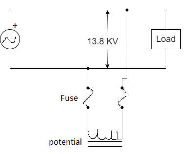
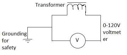
Potential Transformer Working
The potential transformer connected to the power circuit whose voltage should be measured is connected between the phase and the ground. That means the primary winding of a potential transformer is connected to the high voltage circuit and the secondary winding of a transformer is connected to a voltmeter. Due to the mutual induction, the two windings are magnetically coupled to each other and work on the principle of electromagnetic induction.
The decreased voltage is measured across the secondary winding with respect to the voltage across the primary winding using multimeter or voltmeter. Due to the high impedance in the potential transformer, the small current flows through the secondary winding and operates similarly to the ordinary transformer with no or low load. Hence these types of transformers operated at a voltage range of 50 to 200VA.
According to the convention transformer, the transformation ratio is
V2 = N1/N2
‘V1’= voltage of the primary winding
‘V2’ = voltage of the secondary winding
‘N1’= number of turns in the primary winding
‘N2’= number of turns in the secondary winding
The high voltage of a circuit can be determined by using the above equation.
Types of Voltage or Potential Transformers
Based on the function of a potential transformer, there are two types,
Metering voltage transformers
Protection voltage transformers
These are available in single or three-phase and operate with the highest accuracy. These are used to operate and control measuring devices, relays and other devices. Based on the construction, there are
Electromagnetic Potential Transformers
These are similar to the primary transformer, where primary and secondary windings are wounded on a magnetic core. It works on a voltage of above or below 130KV. The primary winding is connected to phase and the secondary winding is connected to ground. These are used in metering, relay and high voltage circuits.
Capacitive Potential Transformers
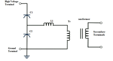
These are also known as capacitive potential dividers or coupling type or bushing type capacitive potential transformers. The series of capacitors are connected to the primary winding or secondary windings. The output voltage across the secondary winding is measured. It is used for power line carrier communication purposes and it is more costly.
Nature of Transients in Power Systems
For the purpose of the present discussion, transients in power systems may be classified into two categories: electromagnetic transients and electromechanical transients.
Switching operations and faults produce step changes in the voltage and current waveforms. On long transmission lines and in transformer and reactor windings, there may be multiple reflections of generated transients. Resonances in the power network create additional frequencies in the waveforms during these phenomena. Another source of electromagnetic transients is lightning. Such transients may be classified as electrical or electromagnetic transients. The effect of these transients is to introduce high-frequency components in the signals. These transients dissipate within a short time and the waveforms then return to a quasi-steady-state condition. The frequencies of signals produced by electromagnetic transients can be summarized as shown below:
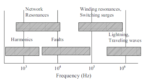
The harmonic phenomena indicated in Fig. Are typically produced by power electronic devices. It should be noted that the harmonic frequencies are multiples of the prevailing network frequency, which may be different from the nominal power frequency. (It should be remembered that phasor estimate performed with sampling rates keyed to nominal power frequency do not eliminate harmonics of off-nominal power system frequency.)
Network resonances are caused by shunt and series capacitors, and line charging capacitances interacting with various reactances in the network. Winding resonance phenomena are characteristic of transformer, generator, and reactor windings. Faults may produce some very high-frequency components, especially if arcing is involved in the fault.
Simulation of transients
Simulation of electromagnetic transients in modern power systems is widely used for the determination of component ratings such as insulation levels and energy absorption capabilities, in the design and optimization process, for testing control and protection systems and for analyzing power systems in general.
The simulation tools or methods for electromagnetic transients fall into the category of EMT-type (or EMTP-type) tools. Such tools are designed to study the power system at a very high precision level by trying to reproduce the actual time-domain waveforms of state variables at any location in the system. The power system is modeled at the circuit level in phase domain and with the representation of all wires and all required components. As for control systems, they are usually represented using block-diagrams. In the time-domain approach there are no inherent limitations in studying harmonics, nonlinear effects and balanced or unbalanced networks.
EMT-type simulation tools are classified into two main categories (families): off-line and real-time. The purpose of an offline simulation tool is to conduct simulations on a generic computer. Although an off-line tool must be designed to be highly efficient using powerful numerical methods and programming techniques, it does not have any time constraints and can be made as precise as possible within the available data, models, and related mathematics.
Real-time simulation tools are capable of generating results in synchronism with a real-time clock. Such tools have the advantage of being capable of interfacing with physical devices and maintaining data exchanges within the real-time clock. The capability to compute and interface within real-time, imposes important restrictions on the design of such tools.
It is feasible to apply EMT-type programs to study transient stability or even small signal stability problems. EMT-type programs can produce more precise simulation results for such studies due to inherent modeling capabilities to account for network nonlinearities and unbalanced conditions. Frequency dependent and voltage dependent load models can be also incorporated. The main disadvantages, especially in off-line tools, remain the computational speed and requirements for data. In EMT-type programs the network equations are solved in time-domain and not with phasors as in transient stability solution methods, which is the main explanation for reduced computational speed.
The building blocks that constitute an EMT-type program are shown in Fig. 1. This figure is labeled as “ultimate” since some of the presented modules or internal features are still at the research stage. Generally speaking, the simulation of a given electrical network is based on the solution of a system of equations
Ax = b. (1)
The unknown variables found in the vector x are usually voltages and currents. Matrix A is used to express topological constraints and component equations, and vector b represents known quantities. All network component models must participate in matrix A and vector b. Although there are several methods for the solution of nonlinear models, the most generic approach is to convert matrix A into a Jacobian and solve (1) through an iterative process. Equation (1) is solved using sparse matrices which provide the capability to solve very large systems efficiently.
Graphical User Interface (GUI)
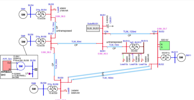
The first entry level to the simulation process is the graphical user interface or data input. Graphical user interfaces with various levels of flexibility and visualization capabilities allow basically drawing the circuit diagram of the simulated system and entering all the appropriate data for selected models. An example of GUI based design is shown in Fig. 2. Modern GUIs are based on the hierarchical design approach with subnetworks and masking. Subnetworks allow simplifying the drawing and hiding details while masking provides data encapsulation. The design of Fig. 2 is using several subnetworks. The 230-kV network is interconnected with a 500-kV network evacuated with all its details into the subnetwork shown in Fig. 2. In a hierarchical design, subnetworks can also contain other subnetworks. Subnetworks can be also used to develop models. The 3-phase transformers shown in Fig. 2 are based on the interconnection of single-phase units. The synchronous machine symbols are also subnetworks containing the load-flow constraints, machine data and also voltage regulator and governor controls subnetwork, as shown in Fig. 2.
Initialization
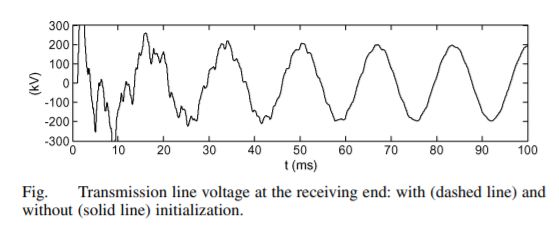
The importance of initialization can be illustrated through the simple example of Fig. 3. The presented waveforms are the voltages at the receiving end of an arrester protected transmission line for two simulation cases. The first case is without any initial conditions and second case is with automatic initialization from steady-state solution. Even if frequency dependent line models (increased damping over constant parameter models) are used, the transients without initialization require more than 100 ms for attaining the actual steady-state response. This will have dramatic computing time consequences on large systems.
A complex subject in automatic initialization is the initialization of systems with power electronics switching devices. It is not obvious to automatically predict commutation patterns in a given operating mode and initialize state variables for harmonic waveforms. A programmed initialization method should find steady-state conditions in significantly less computing time that the brute force approach. In some cases, such as wind generation installations with power electronics devices connected on the rotor side, the best approach is to start with mean-value models or tricked equivalents and to switch onto actual commutating functions after establishing steady state operation. To complete the picture, it is important to mention that initialization concerns also the control system diagrams. It is usually a more complex, but essential feature, since, for example, initialization of synchronous machine variables without initialization of its controls can become worthless. Fully automatic methods do not yet exist, but backward propagation of variables in control blocks from specified initial condition variables is a practical option. In the lack of an automatic initialization, some programs are based on blocking the machine speed for forcing the steady-state, but such methods require additional knowledge on operating conditions and extra user intervention. Some programs also offer a snap-shot feature which allows preserving the steady-state solution conditions (after all time-domain transients have decayed) for successive studies. This option assumes that there are no changes in the saved case.
Statistical and Parametric Methods
The Statistical methods are for simulating with random data and evaluating worst case overvoltages or other probabilities for network variables. A new trend in power system applications is to provide Parametric study options. These options can incorporate arbitrary solution search rules through statistical and/or systematic data laws. Such methods are capable to modify and manipulate data using data scripting languages with full access to visualization and analysis functions. Parametric and statistical studies are particularly useful for estimating failure risks due to lightning and switching events or for evaluating performance limits for controllers.
External Interface
Modern applications have some means of interfacing with external packages or code. The interfacing methods are either object oriented or capable of calling Dynamic Link Libraries (DLLs) or both. Such interfaces are important since they provide a simple interoperability and expandability path. An important user-defined type modeling application is the connection of advanced controllers or relay models available in actual programming language codes.
Time-Domain Module
The time-domain module is the heart of an EMT-type program. It starts from 0-state (all devices are initially deenergized) or from given automatic or manual initial conditions and computes all variables as a function of time. Since component models may have differential equations, it is needed to select and apply a numerical integration technique for their solution. Since many electrical circuits result in a stiff system of equations, the chosen numerical integration method must be stiffly-stable. Such a need excludes explicit methods. In the list of implicit numerical integration methods, the most popular method in industrial applications remains the trapezoidal integration method. It is a polynomial method that can be programmed very efficiently. If an ordinary differential equation is written as

Then the trapezoidal integration solution is given by

The terms found at  constitute history terms and all quantities at time-point
  are also related through network equations. The integration time-step
  can be fixed or variable. The fixed (set by the user) approach has several advantages in power systems. It avoids the time consuming reformulation of system equations and programming issues related to the models. In the case of transmission line models, for example, it is necessary to maintain history buffers for interpolating for propagation delays. The time-step variability will affect the buffer sizes continuously thus slowing down the computations. Fixing the size for the smallest time-step will create memory problems for large cases.
Control Systems
The simulation of control system dynamics is fundamental for studying power system transients. The development of control system solution algorithms based on the block-diagram approach has been initially triggered by the modeling of synchronous machine exciter systems. It was then extensively used in HVDC applications. Control elements can be transfer functions, limiters, gains, summers, integrators and many other mathematical functions. In many applications the block-diagram approach is also used to build and interface user-defined models with the built-in power system components.
OFF-LINE SIMULATION TOOLS
Off-line simulation tools are available on generic computer systems on which they can be easily installed and integrated within the working environment and operating system of the user computer.
The first nodal analysis tool used for power systems was named Electromagnetic Transients Program (EMTP). For historical reasons, the programs available in this category are called EMTP-type tools. The nodal analysis method simply accounts for the equilibrium of current injections at each node by using the nodal admittance matrix Y: Yv = i (4)
The vector of unknown voltage is v(t) and the vector of current injections is i(t). The nodal admittance matrix is also time-dependent since most applications model ideal switches which require inserting or deleting rows and columns. The fact that (4) is real means that it contains only resistances in the symmetrical admittance matrix Y.
This is achieved by applying the trapezoidal integration method through which all branch models with differential equations are given the Norton equivalent resistive companion model for a given integration time-step. The time-step can be fixed or variable. It becomes embedded in Y and each change of time-step requires the complete reformulation of Y.
The most widely used and available packages in power system applications are: ATP, EMTDC and EMTP-RV. These tools are all based on the fixed time-step trapezoidal integration method using (4).
Inverse definite minimum type relay (IDMT):-
IDMT operation
The IDMT relay works on the induction principle, where an aluminium or copper disc rotates between the poles of an electromagnet and a damping magnet. The fluxes induce eddy currents in the disc which interact and produce rotational torque. The disc rotates to a point where it operates a pair of contacts that break the circuit and remove the fault condition.
The effect of plug setting
The plug setting (p.s.) of the relay changes the number of turns in the exciting coil. The winding of the coil is provided with seven taps, which are brought to the front panel and the required tap is selected by a push-in plug. With the plug in the first position (0.5), the whole of the coil is utilised, and the relay is most sensitive. In the seventh position (2.0), only a quarter of the coil is utilised and hence four times more current is required to operate the relay. The seven plug positions are marked 0.5, 0.75, 1, 1.25, 1.5, 1.75, and 2.0 (or 50%, 75%, 100%,125%,150%,175%,200%). Should the plug be removed altogether, the relay automatically defaults to the 2.0 or 200% setting. The effect of altering the plug setting is that for a given current, the greater the plug setting, the longer the time of operation.
The effect of Time Multiplier (TM) setting
The TM (time multiplier) setting of the relay adjusts the "backstop" of the rotating disc. The time of operation is proportional to the distance through which the disc must rotate in order to operate the contacts. With the time multiplier set to one, the backstop is as far back as it can go ( ), and the disc has to move through its maximum travel in order to operate the contacts. If the time multiplier is set to zero then the backstop is positioned so that the contacts are permanently closed. The effect of altering the time multiplier setting is that for a given current, the greater the time multiplier setting, the longer the time of operation .
Relay Characteristics
a. Normal Inverse
3.0 sec relays - i.e. 3.0 sec. At ten times pickup with TMS of 1.0
1.3 sec relays - i.e. 1.3 sec. At 10 times pickup
b. Very Inverse relays
c. Extremely Inverse relays
O/C relaying is very well suited to distribution system protection for the following reasons:-
It is basically simple and inexpensive
Very often the relays do not need to be directional and hence no PT supply is required.
It is possible to use a set of two O/C relays for protection against inter-phase faults and a separate O/C relay for ground faults.
Pick-up Setting
For coordination of the inverse time O/C relays, the pickup current and time dial setting are to be chosen. The pickup of the relays must be choosen such that it will operate for all short circuits in its own line and provide backup for adjoining lines, keeping in view of maximum full load current.
O/C relay Pickup setting = I max. Load
E/F Relay
Pickup setting = 20% of rated current.
For the E/F relay, the load current is not a factor in the selection of pickup settings and is normally set at 20% of rated current.
Time Settings
The actual operating time of the O/C & E/F relays can be varied by proper selection of the ‘Time Dial Setting’ which is selectable from 0.1 to 1.0. Time dial settings are to be chosen by having proper coordination and gradation in the system. Gradations between successive relays are obtained by ‘Selective time interval’ which is usually set between 0.3 to 0.4 Sec.
The operating time of various types of IDMT relays are in the sketches. Also can be obtained by the formulae:
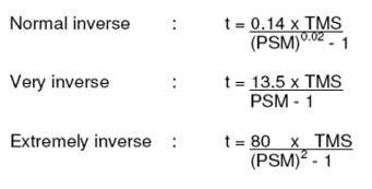

Calculation example for  relay:
For remote bus fault, lets assume a fault current of 3000 Amp through the protected element
Assuming C.T. Ratio on protection line 
Pickup Setting for  relay
relay  (Plug Setting)
 Actual time of operation for
  relay is generally set to grade with the down side system.
Assume time setting required 
Actual Time of Operation (ATO):  TMS (For Normal Inverse)
 Set Time Dial (TMS) for
  relay
relay 
Actual Time of Operation (ATO) for O/L relay
(With TMS:0.1)

Relay Testing
Primary and secondary current injection tests are normally conducted to check the operation of breaker and their protective relays/devices. The protective devices installed vary from circuit to circuit depending on the protection needs and philosphy but typical relays/devices include overload, over current, reverse power, earth fault, differential protection, etc.
Primary Injection Test
Primary injection testing normally involves injecting the actual current required to operate a protective device power through the circuit breaker. Primary injection testing normally requires specialist injection sets/test rings and measurement equipment (particularly for high power and MV and above) and can be extremely arduous where the circuit breaker interrupts large currents, shortening its life or requiring repair after. In many cases, primary injection testing is only conducted by specialists. Testing and research of this form is certainly carried out by circuit breaker manufacturers.
The PI test is usually performed by injecting a current at low voltage (say 5 -10 V) from a purpose built transformer with high current capable secondary winding.
The current is passed through the breaker or busbar section as appropriate. The magnitude of current injected is generally not considered important so long as it is above the minimum operating current determined by the protection relay settings. This test is also carried out to ensure the C.T ratio of current transformers. If this test is carried out after C.T secondary wiring is completed it ensures not only the correct ratio of C.Ts but also the correctness of the entire C.T secondary wiring comprising protection and metering portions. The testing equipment consists of a loading (injection) transformer, controlled by a variable transformer to get the required current on the primary side of the C.T under test.
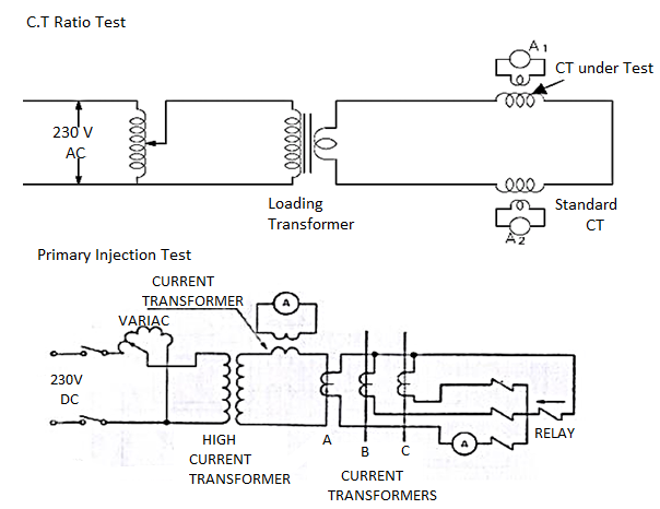
For carrying out the ratio test on C.Ts, Current is passed through the primary windings of the standard C.T and C.T under test. The ratio of the C.T can be determined by comparing the currents in ammeters A1 and A2.
Thus Primary injection is carried out as a test to determine the integrity of the whole secondary protection circuit including CTs, CT leads and control cubicle wiring. In other words it proves that the CB trips in response to an over current. The test is performed after secondary injection tests and CT ratio tests and when all the secondary test links are closed and ready for service. Hence it is often the last test perfomed in the commissioning process. The purpose of PI test can be summarized as :
to ensure wiring connection of protection system is correct
to check CT ratios and polarities
to check Overcurrent relays and Earth Fault relays are set to correct setting
to check Direct Acting Tripping element of the main MCCB.
Secondary Injection Test
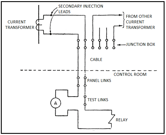
Secondary injection testing is normally different to primary injection testing because it is normally conducted when the circuit breaker is closed but is not carrying any current through its main poles. Secondary injection tests are performed by injecting currents into the relay terminals to determine that the relay is operating correctly and in accordance with its settings. These tests include injecting currents of various magnitudes from minimum operating current all the way up to 10 or 20 times minimum operating current and measuring the relay operating time. This generally involves disconnection of the protective device from it's normal CT and connection to a specialist test set that can inject and measure/record the required operating signal directly into the protective device relay to cause it to operate the circuit breaker. The advantage of secondary injection testing is that the circuit breaker does not have to interrupt large current and only low voltage signals are injected to operate the device. A perceived disadvantage of secondary injection testing is that the actual operation of the 'whole' system is not tested but this may be compensated by the fact that the circuit breaker has operated without having to interrupt a large current and the circuit breaker type has tested and rated by its manufacturer. However, specialist equipment and knowledge is still required, including significant knowledge of the actual protection scheme and philosophy. Furthermore, disconnecting of CT can also lead to potential danger. For this reason, secondary injection testing is also often conducted by specialists. In other words, it is not something that is jumped into without significant experience and knowledge.
C.T Polarity Test
Each current transformer should be individually tested to verify that the polarity markings on the primary and secondary windings are correct. The figure shows the test unit for this. The ammeter ‘A’ is a robust, moving coil, permanent magnet centre zero type instrument. A low voltage battery is used to energise the primary windings through a single pole push button. On closing the push-button, with above C.T ammeter markings, the ammeter should give a positive flick, indicating correct polarity of the C.T.
Open-Secondary Circuits
Secondary circuits of CT's must not be open while primary current flows. Extreme care should be taken to avoid breaking the secondary circuit while primary current is flowing. If the secondary is open-circuited the primary current raises core flux density to saturation and induces a high voltage in the secondary which can endanger human life, and can damage connected apparatus and leads. If it is necessary to change secondary conditions while primary current is flowing, the secondary terminals must be short-circuited while the change is being made. It is recommended that the secondaries of all current transformers be kept short-circuited at all times when not installed in a circuit such as being held in stock or being transported.
References:
1. Wu, Y.H., Dong, X.Z. & Mirsaeidi, S. Modeling and simulation of air-gapped current transformer based on Preisach Theory.
2. J. Mahseredjian, V. Dinavahi and J. A. Martinez, "Simulation Tools for Electromagnetic Transients in Power Systems: Overview and Challenges," in IEEE Transactions on Power Delivery, vol. 24, no. 3, pp. 1657-1669, July 2009
3. Y. G.Paithankar and S. R. Bhide, “Fundamentals of power system protection”, Prentice Hall, India, 2010.
4. A. G. Phadke and J. S. Thorp, “Computer Relaying for Power Systems”, John Wiley & Sons, 1988.
5. A. G. Phadke and J. S. Thorp, “Synchronized Phasor Measurements and their Applications”, Springer, 2008.