Unit 2
Solution to First and Second Order Networks
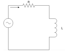
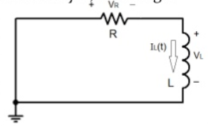
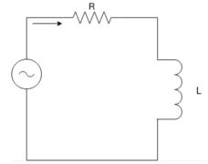
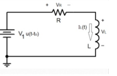
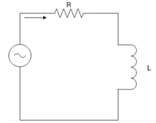
Consider the R-L circuit as shown in the figure:
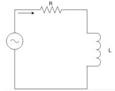
The equation for R-L circuit is given by :
L di/dt + Ri = E(t) ----------------------(1)
This equation models the amount of current i(t) in amperes in a circuit containing resistance R in ohms and inductance L in henry and electromotive force E(t) in volts.
The sum of the voltage drop across the inductor L di/dt and the voltage drop across the resistor Ri is equal to the impressed voltage E(t) where L is the inductance and R is the resistance. Both L and R are constants.
The current i(t) is called the response of the system.
Consider the following example:
Two 9V batteries are connected to a series in which the inductance is ¼ henry and the resistance is 8 ohms. Determine the current i(t) if the initial current is zero.
Solution:
We know that L di/dt + Ri = E(t)
Here L =1/4 H R=8 Ω E(t) = 18V.
¼ di/dt + 8i = 18
Di/dt + 32i = 72 (Linear first order differential equation)
The integrating constant is given by μ(t) = e  32t ---------------(1)
e 32t . Di/dt + e 32 t . 32 i = e 32t . 72 ------------------------(2)
The equation of the left can be written as
d/dt [ e 32t i(t)] = e 32t . 72 ------------------------------(3)
Taking integration on both sides we get  [ e 32t . i] dt =
  e 32t dt ----------(4)
e 32t . i = 72/32 e 32t let u = 32t
Du/32 = 32/32 dt
Du/32 = dt
e 32t . i/ e 32 t = 72/32 e 32t/ e 32t + C / e 32t
i(t) = 72/32 + C e -32t
Since i(0) = 0
9/4 + C =0
C =-9/4
i (t) = 9/4 – 9/4 e -32t
As t-> ∞ i(t) 9/4 because as t ∞ – 9/4 e -32t becomes zero
– 9/4 e -32t ---- transient term
9/4 is called the steady term
9/4 amperes is the steady rate current.
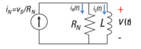
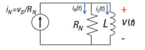
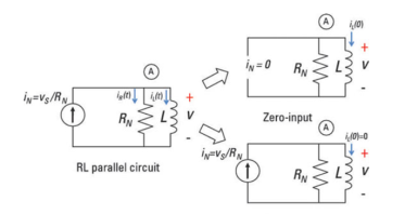
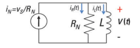
A first-order RL parallel circuit has one resistor (or network of resistors) and a single inductor.
First-order circuits can be analyzed using first-order differential equations.
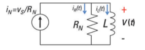
Because the resistor and inductor are connected in parallel they must have the same voltage v(t). The resistor current iR(t) is based on Ohm’s law:
i R (t) = v(t) / R
The element constraint for an inductor is given as
v(t) = L di(t)/dt
Where i(t) is the inductor current and L is the inductance.
Substitute v(t) = L di(t)/dt because you have the same voltage across the resistor and inductor:
i R (t) = (L / R) di(t)/dt
In Kirchhoff’s current law (KCL) the incoming currents are equal to the outgoing currents at a node.
Use KCL at Node A of the sample circuit to get iN(t) = iR(t) =i(t).
Substitute iR(t) into the KCL equation to get
i N (t) = (L/R) d i(t)/dt + i(t)
A circuit containing a single equivalent inductor and an equivalent resistor is a first-order circuit.
i R (t) = (L/R) d i(t) /dt
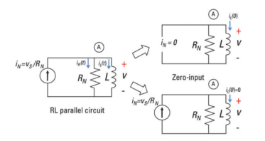
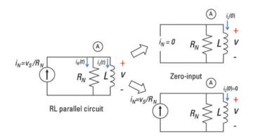
To calculate the zero- input response:
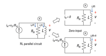 zero-state
The input source is equal to 0: iN(t) = 0 amps. This means no input current for all time.
The first-order differential equation reduces to
i N(t) = 0 = (L/R) di ZL (t) /dt + i zl(t)
i(t) = -(L/R) d i zl(t) /dt
For an input source of no current, the inductor current iZ is called a zero-input response. No external forces are acting on the circuit except for its initial state. The output is due to some initial inductor current I0 at time t = 0.
Assume the inductor current and solution to be
iZl(t) = B e kt
Substitute iZI(t) = Bekt into the differential equation:
I zl(t) = -(L/R) di zl (t) /dt
Replacing iZI(t) with Bekt and
B e kt = - (L/R) d/dt (Bekt )
- (L/R) k (Bekt )
The characteristic equation after factoring out Bekt:
B e kt [ 1 + (L/R) k ] =0
The characteristic equation gives an algebraic problem to solve for the constant k:
1 + (L/R) k =0
k = -R/L
Use k = –R/L and the initial inductor current I0 at t = 0. This implies that B = I0, so the zero-input response iZI(t) gives
i zl (t) = Io e –(R/L)
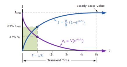
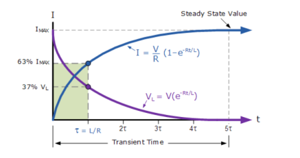
The constant L/R is called the time constant. The time constant provides a measure of how long an inductor current takes to go to 0 or change from one state to another.
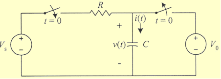
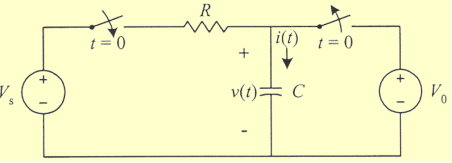
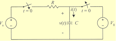
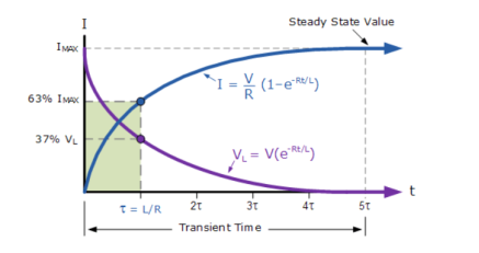
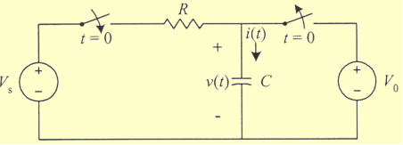
The step response of the circuit is its behaviour when the excitation is the step function which may be voltage or current source.
When t<0 switch is in a closed and opened position for a long time.
At t=0 the instant when the switch is opened and closed
At t>0 switch is not closed and opened after a long time.
For t≤ 0 , v(t) = Vo.
For t> 0
Vs – v(t) = R i(t)
Vs – v(t) = RC dv(t)/dt
1/RC dt = d v(t) / Vs – v(t)
-1/RC dt = d v(t)/ v(t) – Vs
Let u = v(t)
-1/RC dv = du / u – Vs
-t/RC = ln [ (v(t) – Vs) – ln (Vo -Vs)
-t/RC = ln [ v(t) -Vs) / (Vo – Vs)]
v(t) = Vs + (Vo – Vs) e -t/RC
= Vs + (Vo -Vs) e -t/ τ
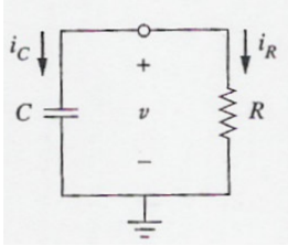
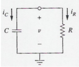
Parallel RC circuit:
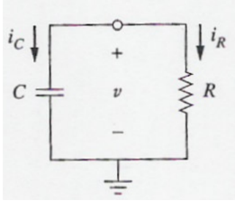
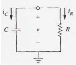
Assume voltage v(t) across the capacitor. Since the capacitor is initially charged at time t=0 the initial voltage is
v(0) =Vo
With the corresponding of the energy stored as
w(0) = ½ C Vo 2
Applying KCL at the top node of the circuit
Ic + ir =0
Ic = C dv/dt and ir = v/ R
C dv/dt + v/R =0
Dv/dt + v /CR =0
This is the first order differential equation.
Rearranging the equation
Dv/v = -dt /RC
Integrating on both sides
Ln v = -t/RC + ln A
Where ln A is integration constant.
Thus,
Ln v/A = -t/ RC
Taking powers of e produces
v(t) = A e -t/RC
But from initial condition v(0) = A = Vo
Thus,
v(t) = Vo e -t/RC
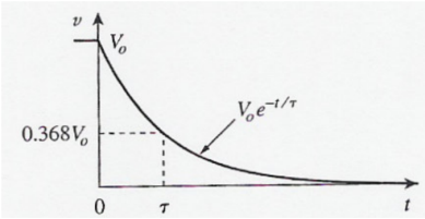
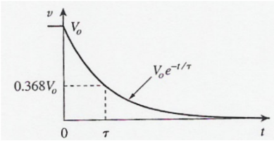
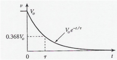
This shows that the voltage response of RC circuit is an exponential decay of the initial voltage. Since the response is due to the initial energy stored and the physical characteristics of the circuit and not due to some external voltage or current source it is called the natural response of the circuit.
The voltage response of the RC circuit is
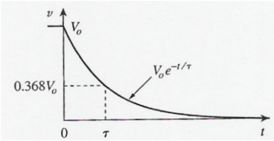
As the time t increases voltage decreases toward zero. The rapidity with which the voltage decreases is expressed in terms of the time constant τ.
This shows that the voltage response of the RC circuit is an exponential decay of the initial voltage. Since the response is due to the intial energy stored and the physical characteristics of the circuit and not on some external voltage or current source it is called the natural response of the circuit.
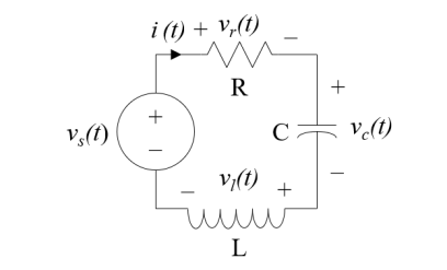
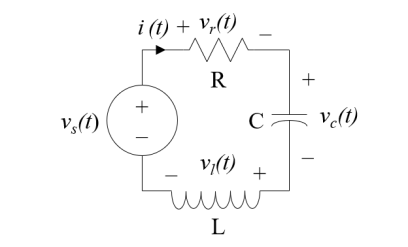
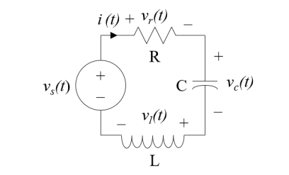
R i(t) + L d i(t)/dt + 1/C  dx = vs(t)
d 2 i(t) / dt 2 + R/L d i(t)/dt + 1/LC i(t) = 1/L d vs(t) /dt
Most circuits with one inductor and capacitor are not easy to analyse hence every voltage and current in the circuit is the solution to the differential equation given by

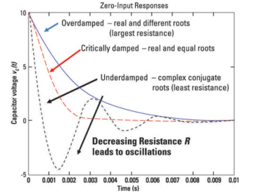
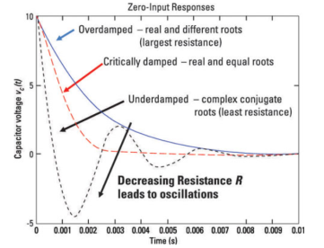
The roots of the characteristic equation whether the complementary solution wiggles.

 , s1 and s2 are real and not equal then

The solution is overdamped.
 are complex then

The solution is underdamped.
If  s1 and s2 are real and equal

The solution is critically damped.
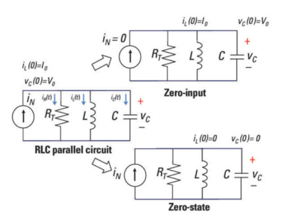
Parallel RLC circuit
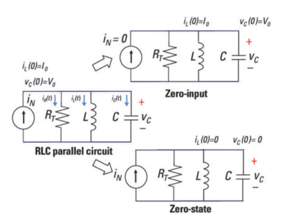
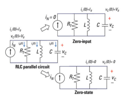
The left diagram shows an input with initial inductor current Io and capacitor voltage Vo. The top-right diagram shows the input current source I N set equal to zero. The bottom-right diagram shows the initial conditions Io and Vo set equal to zero which lets you obtain the zero state response.
Using KCL we get
iN(t) =iR(t) +iC(t) +iL(t)
The resistor current iR(t) is based on the old, reliable Ohm’s law:
i R(t) = v(t)/R
The element constraint for an inductor is given as
v(t) = L di(t) /dt
The current iL(t) is the inductor current, and L is the inductance. This constraint means a changing current generates an inductor voltage. If the inductor current doesn’t change, there’s no inductor voltage, implying a short circuit.
Parallel devices have the same voltage v(t).The inductor voltage v(t) equal to the capacitor voltage to obtain capacitor current iC(t):
Ic(t) = C dv(t)/dt = LC d2 iL(t)/dt 2
Now substitute v(t) = L diL(t)/dt into Ohm’s law, because same voltage appears across the resistor and inductor:
i R (t) = (L/R) d i L(t) /dt
Substitute the values of iR(t) and iC(t) into the KCL equation to get currents in terms of the inductor current:
i N (t) = LC d 2 i L (t) / dt 2 + (L/R) d iL(t)/dt + i L(t)
The RLC parallel circuit is described by a second-order differential equation, so the circuit is a second-order circuit.
The unknown is the inductor current iL(t).
v T(t) = LC d 2 vc(t)/ dt2 + RC dvc(t)/dt + vc (t)
For a parallel circuit the second-order and homogeneous differential equation is given in terms of the inductor current:
0 = d 2 iL /dt 2 + (1/RC) d iL(t)/dt + (1/LC) iL(t)
k 2 + 1/RC k + !?LC =0 -- k1,k2 = - 1/2RC  ½
½  [ (1/RC) 2 – 4/LC]
The preceding equation gives you three possible cases under the radical:
Case 1: [ (1/RC) 2 – 4/LC ] >0 two different roots α 1 and α 2.
Case 2: [(1/RC) 2 – 4/LC] =0 two equal roots (α1=α2)
Case 3: [1/RC) 2 – 4/LC] <0 two complex conjugate roots (α1  j β)
j β)
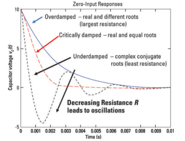
When k1 and k2 are known, we obtain the zero-input response iZI(t). The solution gives you

To find the constants c1 and c2 by using the results found in the RLC series circuit, which are given as
c 1 = k2 Vo – Io/C / k2 – k1
c2 = -k1 Vo + Io/C / k2 -k1
Apply duality to the preceding equation by replacing the voltage, current, and inductance with their duals (current, voltage, and capacitance) to get c1 and c2 for the RLC parallel circuit:
c 1 = k2 Io – Vo/L / k2 -k1
c2 = -k1Io + Vo/L / k2 -k1
For RC circuit
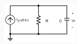
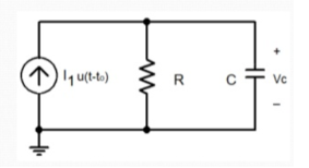
Ic = 0A when t< to
Vc = 0V when t < to
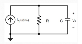
Because I1 =0A (replace it with open circuit)
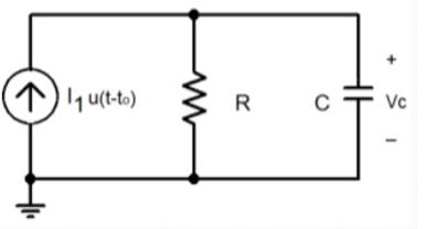
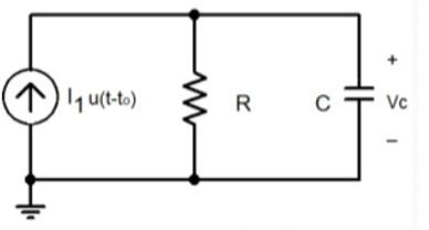
Find the final condition of the voltage across the capacitor
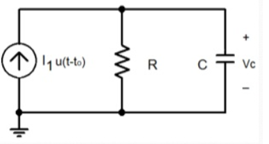
Ic =0A when ͂ ∞ s
Vc = VR = I1R when ~ ∞ s
RL circuit:
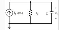
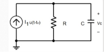
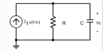
In the time between to and t=∞ s, the capacitor stores energy and currents flow through R and C.
Vc = VR
Ic = C dVc/dt
IR = VR/R
IR + Ic -I1 =0
Vc/R + C dVc/dt – I1 =0
Vc (t) = R I1 [ 1 – e – t-to/ τ] τ=RC
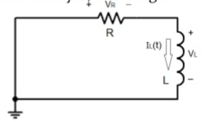
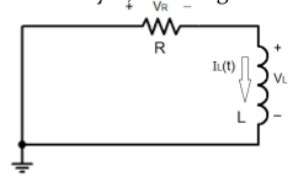
Initial condition is not important as the magnitude of the voltage source in the circuit is equal to 0V when t≤ to.
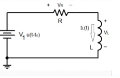
Since the voltage source has only been turned on at t=to the circuit at t ≤ to is shown below:
As the inductor has not stored any energy because no power source has been connected to the circuit all voltages and currents are equal to zero.

So, the final condition of the inductor current needs to be calculated after the voltage source has switched on.
Replace L with a short circuit and calculate IL (∞) .
Final condition:
VL(∞) = 0V
I L (∞) = IR
I R = V1 /R
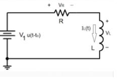
RL circuit
-V1 + VL + VR =0
I L = I R = V R /R
VL = L dIL/dt
DIL/dt + R I R -V1 =0
DIL/dt + R/L IL – V1/L =0
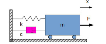
Consider the following example:
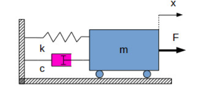
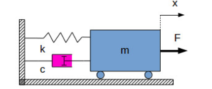
The equation of motion of the body mass is
m. d 2 x/ dt 2 + c . Dx /dt + k.x = F -------------------------(1)
Where:
m [kg] – mass
k [N/m] – spring constant (stiffness)
c [N⋅s/m] – damping coefficient
F [N] – external force acting on the body
x [m] – displacement of the body
The free response of a system is the solution of the describing differential equation of the system, when the input is zero.
In our case the input into the system is the force F [N]. Therefore, in order to verify the free response of the system we have to solve the differential equation:
M . d 2 x / d t2 + c. Dx /dt + k.x =0 -----------------------------(2)
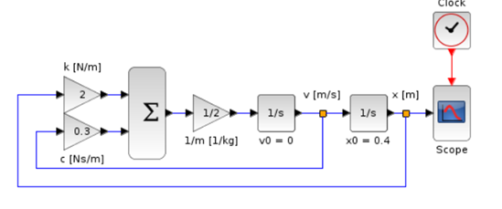
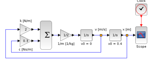
To be able to see the free response, we need an initial condition. For our example we are going to set the initial conditions:
x(0)=0.4
v(0)=0
The free response of the mass spring-damper system will be the variation in time of the displacement x [m].
To integrate equation (2),write it in the following form:
d 2 x/ dt2 = 1/m . ( -c dx/dt – k.x)
Equation (3) is modelled and integrated in Xcos
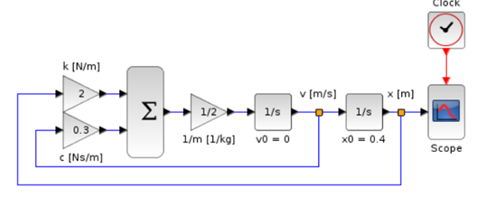
The general equation of a free response system has the differential equation in the form:
 d i x / d t i = 0 -----------------------------(4)
Forced response of a system
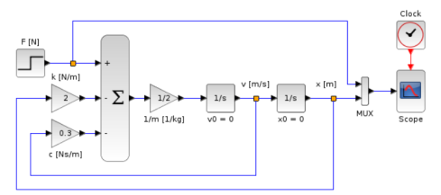
The forced response of a system is the solution of the differential equation describing the system, taking the impact of the input. If the input is force F [N] then
m . d 2 x / d t 2 + c . Dx /dt + k.x = F(t)
To visualise the forced system response of a system, all the initial conditions must be zero:
x(0)=0
v(0)=0
The forced response of the mass spring-damper system will be the variation in time of the displacement x [m].
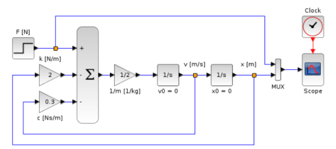
d 2 x / d t2 = 1/m . (F-c . Dx/dt – k.x )
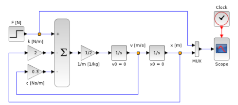
We can reuse the Xcos model from the free system response, the only differences being that there is an input step force added and the initial condition of the position is 0 m.
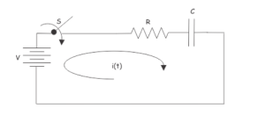
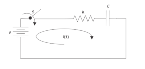
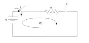
Let us assume, the capacitor is initially unchanged, and the switch S is closed at time t = 0. After closing the switch, electric current i(t) starts flowing through the circuit. Applying Kirchhoff Voltage Law in that single mesh circuit, we get,
v = R i(t) + 1/C  dt
dt
Differentiating both sides with respect to time t, we get
R d i(t) /dt + i(t) /C =0
R di(t)/dt = - i(t)/C
-RC d i(t)/i(t) = dt
d i(t)/ i(t) = -1/R C dt
Integrating both side we get,
 = -1/RC dt
Log e i(t) + log e i(k) = -t/RC
Now, at t = 0, the capacitor behaves as short circuit, so, just after closing the switch, the current through the circuit will be,
Io = V/R
Now, putting this value in equation (i) we get,
k V/R = e 0
k = R/V
Putting the value of k at equation (i) we get,
I(t) = V/R e -t/RC
Now, if we put t = RC in the final expression of circuit current i(t), we get,
I t=RC = V/R e-1
= 0.367 V/R = 0.367 Io or 36.7 % of Io
From the above mathematical expression it is clear that RC is the time in second during which the current in a charging capacitor diminishes to 36.7 percent from its initial value. Initial value means, current at the time of switching on the unchangedcapacitor.
This term is quite significant in analyzing behaviour of capacitive as well as inductive circuit. This term is known as time constant.
So, time constant is the duration in seconds during which the current through a capacities circuit becomes 36.7 percent of its initial value. This is numerically equal to the product of resistance and capacitance value of the circuit. Time constant is normally denoted by τ (tau). So,
In complex RC circuit, time constant will be product of equivalent resistance and capacitance of circuit.
If we plot current i(t).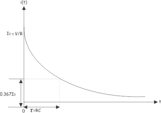
At t = 0, the current through the capacitor circuit is
Io = V/R
At t = RC, the current through the capacitor is
0.367 Io = 0.367 V/R
Example : 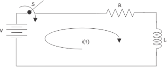
Applying KVL in the above circuit. We get,
V = R i(t) + L d i(t)/dt
The equation can also be solved using Laplace transform technique. For that we have to take Laplace transform of the equation at both sides,
V/s = L [ s I(s) – i(0+) ] + R I(s)
V/s = L s I(s) + R I(s)
I(s) = V / s(Ls + R)
Hence, in this equation.
I(0+) =0
Since, current just after switch is on, current through the inductor will be zero.
Now,
I(s) = No / Ls (s + R/L) = Vo/L . 1/ s(s + R/L)
Taking inverse Laplace of the above equation, we get,
i(t) = No/R [ 1 – e -Rt/L]
Now, if we put,
t = L/R
We get,
i(L/R) = Vo/R [ 1- e-1 ] = 0.633 Vo/R
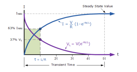
So, at RL circuit, at time = L/R sec the current becomes 63.3% of its final steady state value. The L/R is known as time constant of an RL circuit . Let us plot the current of inductor circuit.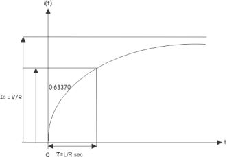
The time constant of an RL circuit is the ratio of inductance to resistance of the circuit.
Scroll back to top
- Transient response
- Steady state response
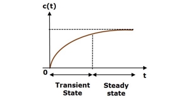
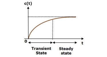
The response of control system in time domain is shown in the following figure.
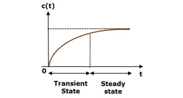
Here, both the transient and the steady states are indicated in the figure. The responses corresponding to these states are known as transient and steady state responses.
Mathematically, we can write the time response c(t) as
c(t)=ctr(t)+css(t)
Where,
- ctr(t) is the transient response
- css(t) is the steady state response
Transient Response
After applying input to the control system, output takes certain time to reach steady state. So, the output will be in transient state till it goes to a steady state. Therefore, the response of the control system during the transient state is known as transient response.
The transient response will be zero for large values of ‘t’. Ideally, this value of ‘t’ is infinity and practically, it is five times constant.
Mathematically, we can write it as
Limt→∞ctr(t)=0
Steady state Response
The part of the time response that remains even after the transient response has zero value for large values of ‘t’ is known as steady state response. This means, the transient response will be zero even during the steady state.
Find the transient and steady state terms of the time response of the control system
c(t)=10+5e−t
Here, the second term 5e−t will be zero as t denotes infinity.
So, this is the transient term.
And the first term 10 remains even as t approaches infinity. So, this is the steady state term.
References:
- Network theory by A.V Bakshi, U.A Bakshi
- Network Theory Analysis and Synthesis by Smarajit Ghosh
- Networks: An introduction by Mark Newman
- Network Theory (Bput) book by Satpathy
Unit 2
Solution to First and Second Order Networks
Consider the R-L circuit as shown in the figure:
The equation for R-L circuit is given by :
L di/dt + Ri = E(t) ----------------------(1)
This equation models the amount of current i(t) in amperes in a circuit containing resistance R in ohms and inductance L in henry and electromotive force E(t) in volts.
The sum of the voltage drop across the inductor L di/dt and the voltage drop across the resistor Ri is equal to the impressed voltage E(t) where L is the inductance and R is the resistance. Both L and R are constants.
The current i(t) is called the response of the system.
Consider the following example:
Two 9V batteries are connected to a series in which the inductance is ¼ henry and the resistance is 8 ohms. Determine the current i(t) if the initial current is zero.
Solution:
We know that L di/dt + Ri = E(t)
Here L =1/4 H R=8 Ω E(t) = 18V.
¼ di/dt + 8i = 18
Di/dt + 32i = 72 (Linear first order differential equation)
The integrating constant is given by μ(t) = e  32t ---------------(1)
e 32t . Di/dt + e 32 t . 32 i = e 32t . 72 ------------------------(2)
The equation of the left can be written as
d/dt [ e 32t i(t)] = e 32t . 72 ------------------------------(3)
Taking integration on both sides we get  [ e 32t . i] dt =
  e 32t dt ----------(4)
e 32t . i = 72/32 e 32t let u = 32t
Du/32 = 32/32 dt
Du/32 = dt
e 32t . i/ e 32 t = 72/32 e 32t/ e 32t + C / e 32t
i(t) = 72/32 + C e -32t
Since i(0) = 0
9/4 + C =0
C =-9/4
i (t) = 9/4 – 9/4 e -32t
As t-> ∞ i(t) 9/4 because as t ∞ – 9/4 e -32t becomes zero
– 9/4 e -32t ---- transient term
9/4 is called the steady term
9/4 amperes is the steady rate current.
A first-order RL parallel circuit has one resistor (or network of resistors) and a single inductor.
First-order circuits can be analyzed using first-order differential equations.
Because the resistor and inductor are connected in parallel they must have the same voltage v(t). The resistor current iR(t) is based on Ohm’s law:
i R (t) = v(t) / R
The element constraint for an inductor is given as
v(t) = L di(t)/dt
Where i(t) is the inductor current and L is the inductance.
Substitute v(t) = L di(t)/dt because you have the same voltage across the resistor and inductor:
i R (t) = (L / R) di(t)/dt
In Kirchhoff’s current law (KCL) the incoming currents are equal to the outgoing currents at a node.
Use KCL at Node A of the sample circuit to get iN(t) = iR(t) =i(t).
Substitute iR(t) into the KCL equation to get
i N (t) = (L/R) d i(t)/dt + i(t)
A circuit containing a single equivalent inductor and an equivalent resistor is a first-order circuit.
i R (t) = (L/R) d i(t) /dt
To calculate the zero- input response:
 zero-state
The input source is equal to 0: iN(t) = 0 amps. This means no input current for all time.
The first-order differential equation reduces to
i N(t) = 0 = (L/R) di ZL (t) /dt + i zl(t)
i(t) = -(L/R) d i zl(t) /dt
For an input source of no current, the inductor current iZ is called a zero-input response. No external forces are acting on the circuit except for its initial state. The output is due to some initial inductor current I0 at time t = 0.
Assume the inductor current and solution to be
iZl(t) = B e kt
Substitute iZI(t) = Bekt into the differential equation:
I zl(t) = -(L/R) di zl (t) /dt
Replacing iZI(t) with Bekt and
B e kt = - (L/R) d/dt (Bekt )
- (L/R) k (Bekt )
The characteristic equation after factoring out Bekt:
B e kt [ 1 + (L/R) k ] =0
The characteristic equation gives an algebraic problem to solve for the constant k:
1 + (L/R) k =0
k = -R/L
Use k = –R/L and the initial inductor current I0 at t = 0. This implies that B = I0, so the zero-input response iZI(t) gives
i zl (t) = Io e –(R/L)
The constant L/R is called the time constant. The time constant provides a measure of how long an inductor current takes to go to 0 or change from one state to another.
The step response of the circuit is its behaviour when the excitation is the step function which may be voltage or current source.
When t<0 switch is in a closed and opened position for a long time.
At t=0 the instant when the switch is opened and closed
At t>0 switch is not closed and opened after a long time.
For t≤ 0 , v(t) = Vo.
For t> 0
Vs – v(t) = R i(t)
Vs – v(t) = RC dv(t)/dt
1/RC dt = d v(t) / Vs – v(t)
-1/RC dt = d v(t)/ v(t) – Vs
Let u = v(t)
-1/RC dv = du / u – Vs
-t/RC = ln [ (v(t) – Vs) – ln (Vo -Vs)
-t/RC = ln [ v(t) -Vs) / (Vo – Vs)]
v(t) = Vs + (Vo – Vs) e -t/RC
= Vs + (Vo -Vs) e -t/ τ
Parallel RC circuit:
Assume voltage v(t) across the capacitor. Since the capacitor is initially charged at time t=0 the initial voltage is
v(0) =Vo
With the corresponding of the energy stored as
w(0) = ½ C Vo 2
Applying KCL at the top node of the circuit
Ic + ir =0
Ic = C dv/dt and ir = v/ R
C dv/dt + v/R =0
Dv/dt + v /CR =0
This is the first order differential equation.
Rearranging the equation
Dv/v = -dt /RC
Integrating on both sides
Ln v = -t/RC + ln A
Where ln A is integration constant.
Thus,
Ln v/A = -t/ RC
Taking powers of e produces
v(t) = A e -t/RC
But from initial condition v(0) = A = Vo
Thus,
v(t) = Vo e -t/RC
This shows that the voltage response of RC circuit is an exponential decay of the initial voltage. Since the response is due to the initial energy stored and the physical characteristics of the circuit and not due to some external voltage or current source it is called the natural response of the circuit.
The voltage response of the RC circuit is
As the time t increases voltage decreases toward zero. The rapidity with which the voltage decreases is expressed in terms of the time constant τ.
This shows that the voltage response of the RC circuit is an exponential decay of the initial voltage. Since the response is due to the intial energy stored and the physical characteristics of the circuit and not on some external voltage or current source it is called the natural response of the circuit.
R i(t) + L d i(t)/dt + 1/C  dx = vs(t)
d 2 i(t) / dt 2 + R/L d i(t)/dt + 1/LC i(t) = 1/L d vs(t) /dt
Most circuits with one inductor and capacitor are not easy to analyse hence every voltage and current in the circuit is the solution to the differential equation given by

The roots of the characteristic equation whether the complementary solution wiggles.

 , s1 and s2 are real and not equal then

The solution is overdamped.
 are complex then

The solution is underdamped.
If  s1 and s2 are real and equal

The solution is critically damped.
Parallel RLC circuit
The left diagram shows an input with initial inductor current Io and capacitor voltage Vo. The top-right diagram shows the input current source I N set equal to zero. The bottom-right diagram shows the initial conditions Io and Vo set equal to zero which lets you obtain the zero state response.
Using KCL we get
iN(t) =iR(t) +iC(t) +iL(t)
The resistor current iR(t) is based on the old, reliable Ohm’s law:
i R(t) = v(t)/R
The element constraint for an inductor is given as
v(t) = L di(t) /dt
The current iL(t) is the inductor current, and L is the inductance. This constraint means a changing current generates an inductor voltage. If the inductor current doesn’t change, there’s no inductor voltage, implying a short circuit.
Parallel devices have the same voltage v(t).The inductor voltage v(t) equal to the capacitor voltage to obtain capacitor current iC(t):
Ic(t) = C dv(t)/dt = LC d2 iL(t)/dt 2
Now substitute v(t) = L diL(t)/dt into Ohm’s law, because same voltage appears across the resistor and inductor:
i R (t) = (L/R) d i L(t) /dt
Substitute the values of iR(t) and iC(t) into the KCL equation to get currents in terms of the inductor current:
i N (t) = LC d 2 i L (t) / dt 2 + (L/R) d iL(t)/dt + i L(t)
The RLC parallel circuit is described by a second-order differential equation, so the circuit is a second-order circuit.
The unknown is the inductor current iL(t).
v T(t) = LC d 2 vc(t)/ dt2 + RC dvc(t)/dt + vc (t)
For a parallel circuit the second-order and homogeneous differential equation is given in terms of the inductor current:
0 = d 2 iL /dt 2 + (1/RC) d iL(t)/dt + (1/LC) iL(t)
k 2 + 1/RC k + !?LC =0 -- k1,k2 = - 1/2RC  ½
½  [ (1/RC) 2 – 4/LC]
The preceding equation gives you three possible cases under the radical:
Case 1: [ (1/RC) 2 – 4/LC ] >0 two different roots α 1 and α 2.
Case 2: [(1/RC) 2 – 4/LC] =0 two equal roots (α1=α2)
Case 3: [1/RC) 2 – 4/LC] <0 two complex conjugate roots (α1  j β)
j β)
When k1 and k2 are known, we obtain the zero-input response iZI(t). The solution gives you

To find the constants c1 and c2 by using the results found in the RLC series circuit, which are given as
c 1 = k2 Vo – Io/C / k2 – k1
c2 = -k1 Vo + Io/C / k2 -k1
Apply duality to the preceding equation by replacing the voltage, current, and inductance with their duals (current, voltage, and capacitance) to get c1 and c2 for the RLC parallel circuit:
c 1 = k2 Io – Vo/L / k2 -k1
c2 = -k1Io + Vo/L / k2 -k1
For RC circuit
Ic = 0A when t< to
Vc = 0V when t < to
Because I1 =0A (replace it with open circuit)
Find the final condition of the voltage across the capacitor
Ic =0A when ͂ ∞ s
Vc = VR = I1R when ~ ∞ s
RL circuit:
In the time between to and t=∞ s, the capacitor stores energy and currents flow through R and C.
Vc = VR
Ic = C dVc/dt
IR = VR/R
IR + Ic -I1 =0
Vc/R + C dVc/dt – I1 =0
Vc (t) = R I1 [ 1 – e – t-to/ τ] τ=RC
Initial condition is not important as the magnitude of the voltage source in the circuit is equal to 0V when t≤ to.
Since the voltage source has only been turned on at t=to the circuit at t ≤ to is shown below:
As the inductor has not stored any energy because no power source has been connected to the circuit all voltages and currents are equal to zero.

So, the final condition of the inductor current needs to be calculated after the voltage source has switched on.
Replace L with a short circuit and calculate IL (∞) .
Final condition:
VL(∞) = 0V
I L (∞) = IR
I R = V1 /R
RL circuit
-V1 + VL + VR =0
I L = I R = V R /R
VL = L dIL/dt
DIL/dt + R I R -V1 =0
DIL/dt + R/L IL – V1/L =0
Unit 2
Solution to First and Second Order Networks
Consider the R-L circuit as shown in the figure:
The equation for R-L circuit is given by :
L di/dt + Ri = E(t) ----------------------(1)
This equation models the amount of current i(t) in amperes in a circuit containing resistance R in ohms and inductance L in henry and electromotive force E(t) in volts.
The sum of the voltage drop across the inductor L di/dt and the voltage drop across the resistor Ri is equal to the impressed voltage E(t) where L is the inductance and R is the resistance. Both L and R are constants.
The current i(t) is called the response of the system.
Consider the following example:
Two 9V batteries are connected to a series in which the inductance is ¼ henry and the resistance is 8 ohms. Determine the current i(t) if the initial current is zero.
Solution:
We know that L di/dt + Ri = E(t)
Here L =1/4 H R=8 Ω E(t) = 18V.
¼ di/dt + 8i = 18
Di/dt + 32i = 72 (Linear first order differential equation)
The integrating constant is given by μ(t) = e  32t ---------------(1)
e 32t . Di/dt + e 32 t . 32 i = e 32t . 72 ------------------------(2)
The equation of the left can be written as
d/dt [ e 32t i(t)] = e 32t . 72 ------------------------------(3)
Taking integration on both sides we get  [ e 32t . i] dt =
  e 32t dt ----------(4)
e 32t . i = 72/32 e 32t let u = 32t
Du/32 = 32/32 dt
Du/32 = dt
e 32t . i/ e 32 t = 72/32 e 32t/ e 32t + C / e 32t
i(t) = 72/32 + C e -32t
Since i(0) = 0
9/4 + C =0
C =-9/4
i (t) = 9/4 – 9/4 e -32t
As t-> ∞ i(t) 9/4 because as t ∞ – 9/4 e -32t becomes zero
– 9/4 e -32t ---- transient term
9/4 is called the steady term
9/4 amperes is the steady rate current.
A first-order RL parallel circuit has one resistor (or network of resistors) and a single inductor.
First-order circuits can be analyzed using first-order differential equations.
Because the resistor and inductor are connected in parallel they must have the same voltage v(t). The resistor current iR(t) is based on Ohm’s law:
i R (t) = v(t) / R
The element constraint for an inductor is given as
v(t) = L di(t)/dt
Where i(t) is the inductor current and L is the inductance.
Substitute v(t) = L di(t)/dt because you have the same voltage across the resistor and inductor:
i R (t) = (L / R) di(t)/dt
In Kirchhoff’s current law (KCL) the incoming currents are equal to the outgoing currents at a node.
Use KCL at Node A of the sample circuit to get iN(t) = iR(t) =i(t).
Substitute iR(t) into the KCL equation to get
i N (t) = (L/R) d i(t)/dt + i(t)
A circuit containing a single equivalent inductor and an equivalent resistor is a first-order circuit.
i R (t) = (L/R) d i(t) /dt
To calculate the zero- input response:
 zero-state
The input source is equal to 0: iN(t) = 0 amps. This means no input current for all time.
The first-order differential equation reduces to
i N(t) = 0 = (L/R) di ZL (t) /dt + i zl(t)
i(t) = -(L/R) d i zl(t) /dt
For an input source of no current, the inductor current iZ is called a zero-input response. No external forces are acting on the circuit except for its initial state. The output is due to some initial inductor current I0 at time t = 0.
Assume the inductor current and solution to be
iZl(t) = B e kt
Substitute iZI(t) = Bekt into the differential equation:
I zl(t) = -(L/R) di zl (t) /dt
Replacing iZI(t) with Bekt and
B e kt = - (L/R) d/dt (Bekt )
- (L/R) k (Bekt )
The characteristic equation after factoring out Bekt:
B e kt [ 1 + (L/R) k ] =0
The characteristic equation gives an algebraic problem to solve for the constant k:
1 + (L/R) k =0
k = -R/L
Use k = –R/L and the initial inductor current I0 at t = 0. This implies that B = I0, so the zero-input response iZI(t) gives
i zl (t) = Io e –(R/L)
The constant L/R is called the time constant. The time constant provides a measure of how long an inductor current takes to go to 0 or change from one state to another.
The step response of the circuit is its behaviour when the excitation is the step function which may be voltage or current source.
When t<0 switch is in a closed and opened position for a long time.
At t=0 the instant when the switch is opened and closed
At t>0 switch is not closed and opened after a long time.
For t≤ 0 , v(t) = Vo.
For t> 0
Vs – v(t) = R i(t)
Vs – v(t) = RC dv(t)/dt
1/RC dt = d v(t) / Vs – v(t)
-1/RC dt = d v(t)/ v(t) – Vs
Let u = v(t)
-1/RC dv = du / u – Vs
-t/RC = ln [ (v(t) – Vs) – ln (Vo -Vs)
-t/RC = ln [ v(t) -Vs) / (Vo – Vs)]
v(t) = Vs + (Vo – Vs) e -t/RC
= Vs + (Vo -Vs) e -t/ τ
Parallel RC circuit:
Assume voltage v(t) across the capacitor. Since the capacitor is initially charged at time t=0 the initial voltage is
v(0) =Vo
With the corresponding of the energy stored as
w(0) = ½ C Vo 2
Applying KCL at the top node of the circuit
Ic + ir =0
Ic = C dv/dt and ir = v/ R
C dv/dt + v/R =0
Dv/dt + v /CR =0
This is the first order differential equation.
Rearranging the equation
Dv/v = -dt /RC
Integrating on both sides
Ln v = -t/RC + ln A
Where ln A is integration constant.
Thus,
Ln v/A = -t/ RC
Taking powers of e produces
v(t) = A e -t/RC
But from initial condition v(0) = A = Vo
Thus,
v(t) = Vo e -t/RC
This shows that the voltage response of RC circuit is an exponential decay of the initial voltage. Since the response is due to the initial energy stored and the physical characteristics of the circuit and not due to some external voltage or current source it is called the natural response of the circuit.
The voltage response of the RC circuit is
As the time t increases voltage decreases toward zero. The rapidity with which the voltage decreases is expressed in terms of the time constant τ.
This shows that the voltage response of the RC circuit is an exponential decay of the initial voltage. Since the response is due to the intial energy stored and the physical characteristics of the circuit and not on some external voltage or current source it is called the natural response of the circuit.
R i(t) + L d i(t)/dt + 1/C  dx = vs(t)
d 2 i(t) / dt 2 + R/L d i(t)/dt + 1/LC i(t) = 1/L d vs(t) /dt
Most circuits with one inductor and capacitor are not easy to analyse hence every voltage and current in the circuit is the solution to the differential equation given by

The roots of the characteristic equation whether the complementary solution wiggles.

 , s1 and s2 are real and not equal then

The solution is overdamped.
 are complex then

The solution is underdamped.
If  s1 and s2 are real and equal

The solution is critically damped.
Parallel RLC circuit
The left diagram shows an input with initial inductor current Io and capacitor voltage Vo. The top-right diagram shows the input current source I N set equal to zero. The bottom-right diagram shows the initial conditions Io and Vo set equal to zero which lets you obtain the zero state response.
Using KCL we get
iN(t) =iR(t) +iC(t) +iL(t)
The resistor current iR(t) is based on the old, reliable Ohm’s law:
i R(t) = v(t)/R
The element constraint for an inductor is given as
v(t) = L di(t) /dt
The current iL(t) is the inductor current, and L is the inductance. This constraint means a changing current generates an inductor voltage. If the inductor current doesn’t change, there’s no inductor voltage, implying a short circuit.
Parallel devices have the same voltage v(t).The inductor voltage v(t) equal to the capacitor voltage to obtain capacitor current iC(t):
Ic(t) = C dv(t)/dt = LC d2 iL(t)/dt 2
Now substitute v(t) = L diL(t)/dt into Ohm’s law, because same voltage appears across the resistor and inductor:
i R (t) = (L/R) d i L(t) /dt
Substitute the values of iR(t) and iC(t) into the KCL equation to get currents in terms of the inductor current:
i N (t) = LC d 2 i L (t) / dt 2 + (L/R) d iL(t)/dt + i L(t)
The RLC parallel circuit is described by a second-order differential equation, so the circuit is a second-order circuit.
The unknown is the inductor current iL(t).
v T(t) = LC d 2 vc(t)/ dt2 + RC dvc(t)/dt + vc (t)
For a parallel circuit the second-order and homogeneous differential equation is given in terms of the inductor current:
0 = d 2 iL /dt 2 + (1/RC) d iL(t)/dt + (1/LC) iL(t)
k 2 + 1/RC k + !?LC =0 -- k1,k2 = - 1/2RC  ½
½  [ (1/RC) 2 – 4/LC]
The preceding equation gives you three possible cases under the radical:
Case 1: [ (1/RC) 2 – 4/LC ] >0 two different roots α 1 and α 2.
Case 2: [(1/RC) 2 – 4/LC] =0 two equal roots (α1=α2)
Case 3: [1/RC) 2 – 4/LC] <0 two complex conjugate roots (α1  j β)
j β)
When k1 and k2 are known, we obtain the zero-input response iZI(t). The solution gives you

To find the constants c1 and c2 by using the results found in the RLC series circuit, which are given as
c 1 = k2 Vo – Io/C / k2 – k1
c2 = -k1 Vo + Io/C / k2 -k1
Apply duality to the preceding equation by replacing the voltage, current, and inductance with their duals (current, voltage, and capacitance) to get c1 and c2 for the RLC parallel circuit:
c 1 = k2 Io – Vo/L / k2 -k1
c2 = -k1Io + Vo/L / k2 -k1
For RC circuit
Ic = 0A when t< to
Vc = 0V when t < to
Because I1 =0A (replace it with open circuit)
Find the final condition of the voltage across the capacitor
Ic =0A when ͂ ∞ s
Vc = VR = I1R when ~ ∞ s
RL circuit:
In the time between to and t=∞ s, the capacitor stores energy and currents flow through R and C.
Vc = VR
Ic = C dVc/dt
IR = VR/R
IR + Ic -I1 =0
Vc/R + C dVc/dt – I1 =0
Vc (t) = R I1 [ 1 – e – t-to/ τ] τ=RC
Initial condition is not important as the magnitude of the voltage source in the circuit is equal to 0V when t≤ to.
Since the voltage source has only been turned on at t=to the circuit at t ≤ to is shown below:
As the inductor has not stored any energy because no power source has been connected to the circuit all voltages and currents are equal to zero.

So, the final condition of the inductor current needs to be calculated after the voltage source has switched on.
Replace L with a short circuit and calculate IL (∞) .
Final condition:
VL(∞) = 0V
I L (∞) = IR
I R = V1 /R
RL circuit
-V1 + VL + VR =0
I L = I R = V R /R
VL = L dIL/dt
DIL/dt + R I R -V1 =0
DIL/dt + R/L IL – V1/L =0
Consider the following example:
The equation of motion of the body mass is
m. d 2 x/ dt 2 + c . Dx /dt + k.x = F -------------------------(1)
Where:
m [kg] – mass
k [N/m] – spring constant (stiffness)
c [N⋅s/m] – damping coefficient
F [N] – external force acting on the body
x [m] – displacement of the body
The free response of a system is the solution of the describing differential equation of the system, when the input is zero.
In our case the input into the system is the force F [N]. Therefore, in order to verify the free response of the system we have to solve the differential equation:
M . d 2 x / d t2 + c. Dx /dt + k.x =0 -----------------------------(2)
To be able to see the free response, we need an initial condition. For our example we are going to set the initial conditions:
x(0)=0.4
v(0)=0
The free response of the mass spring-damper system will be the variation in time of the displacement x [m].
To integrate equation (2),write it in the following form:
d 2 x/ dt2 = 1/m . ( -c dx/dt – k.x)
Equation (3) is modelled and integrated in Xcos
The general equation of a free response system has the differential equation in the form:
 d i x / d t i = 0 -----------------------------(4)
Forced response of a system
The forced response of a system is the solution of the differential equation describing the system, taking the impact of the input. If the input is force F [N] then
m . d 2 x / d t 2 + c . Dx /dt + k.x = F(t)
To visualise the forced system response of a system, all the initial conditions must be zero:
x(0)=0
v(0)=0
The forced response of the mass spring-damper system will be the variation in time of the displacement x [m].
d 2 x / d t2 = 1/m . (F-c . Dx/dt – k.x )
We can reuse the Xcos model from the free system response, the only differences being that there is an input step force added and the initial condition of the position is 0 m.
Let us assume, the capacitor is initially unchanged, and the switch S is closed at time t = 0. After closing the switch, electric current i(t) starts flowing through the circuit. Applying Kirchhoff Voltage Law in that single mesh circuit, we get,
v = R i(t) + 1/C  dt
dt
Differentiating both sides with respect to time t, we get
R d i(t) /dt + i(t) /C =0
R di(t)/dt = - i(t)/C
-RC d i(t)/i(t) = dt
d i(t)/ i(t) = -1/R C dt
Integrating both side we get,
 = -1/RC dt
Log e i(t) + log e i(k) = -t/RC
Now, at t = 0, the capacitor behaves as short circuit, so, just after closing the switch, the current through the circuit will be,
Io = V/R
Now, putting this value in equation (i) we get,
k V/R = e 0
k = R/V
Putting the value of k at equation (i) we get,
I(t) = V/R e -t/RC
Now, if we put t = RC in the final expression of circuit current i(t), we get,
I t=RC = V/R e-1
= 0.367 V/R = 0.367 Io or 36.7 % of Io
From the above mathematical expression it is clear that RC is the time in second during which the current in a charging capacitor diminishes to 36.7 percent from its initial value. Initial value means, current at the time of switching on the unchangedcapacitor.
This term is quite significant in analyzing behaviour of capacitive as well as inductive circuit. This term is known as time constant.
So, time constant is the duration in seconds during which the current through a capacities circuit becomes 36.7 percent of its initial value. This is numerically equal to the product of resistance and capacitance value of the circuit. Time constant is normally denoted by τ (tau). So,
In complex RC circuit, time constant will be product of equivalent resistance and capacitance of circuit.
If we plot current i(t).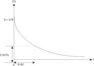
At t = 0, the current through the capacitor circuit is
Io = V/R
At t = RC, the current through the capacitor is
0.367 Io = 0.367 V/R
Example : 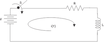
Applying KVL in the above circuit. We get,
V = R i(t) + L d i(t)/dt
The equation can also be solved using Laplace transform technique. For that we have to take Laplace transform of the equation at both sides,
V/s = L [ s I(s) – i(0+) ] + R I(s)
V/s = L s I(s) + R I(s)
I(s) = V / s(Ls + R)
Hence, in this equation.
I(0+) =0
Since, current just after switch is on, current through the inductor will be zero.
Now,
I(s) = No / Ls (s + R/L) = Vo/L . 1/ s(s + R/L)
Taking inverse Laplace of the above equation, we get,
i(t) = No/R [ 1 – e -Rt/L]
Now, if we put,
t = L/R
We get,
i(L/R) = Vo/R [ 1- e-1 ] = 0.633 Vo/R
So, at RL circuit, at time = L/R sec the current becomes 63.3% of its final steady state value. The L/R is known as time constant of an RL circuit . Let us plot the current of inductor circuit.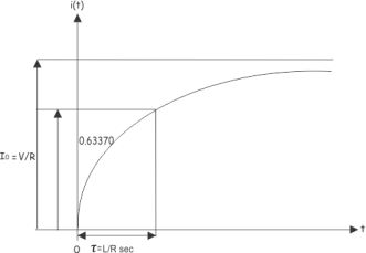
The time constant of an RL circuit is the ratio of inductance to resistance of the circuit.
Scroll back to top
- Transient response
- Steady state response
The response of control system in time domain is shown in the following figure.
Here, both the transient and the steady states are indicated in the figure. The responses corresponding to these states are known as transient and steady state responses.
Mathematically, we can write the time response c(t) as
c(t)=ctr(t)+css(t)
Where,
- ctr(t) is the transient response
- css(t) is the steady state response
Transient Response
After applying input to the control system, output takes certain time to reach steady state. So, the output will be in transient state till it goes to a steady state. Therefore, the response of the control system during the transient state is known as transient response.
The transient response will be zero for large values of ‘t’. Ideally, this value of ‘t’ is infinity and practically, it is five times constant.
Mathematically, we can write it as
Limt→∞ctr(t)=0
Steady state Response
The part of the time response that remains even after the transient response has zero value for large values of ‘t’ is known as steady state response. This means, the transient response will be zero even during the steady state.
Find the transient and steady state terms of the time response of the control system
c(t)=10+5e−t
Here, the second term 5e−t will be zero as t denotes infinity.
So, this is the transient term.
And the first term 10 remains even as t approaches infinity. So, this is the steady state term.
References:
- Network theory by A.V Bakshi, U.A Bakshi
- Network Theory Analysis and Synthesis by Smarajit Ghosh
- Networks: An introduction by Mark Newman
- Network Theory (Bput) book by Satpathy
Unit 2
Solution to First and Second Order Networks
Consider the R-L circuit as shown in the figure:
The equation for R-L circuit is given by :
L di/dt + Ri = E(t) ----------------------(1)
This equation models the amount of current i(t) in amperes in a circuit containing resistance R in ohms and inductance L in henry and electromotive force E(t) in volts.
The sum of the voltage drop across the inductor L di/dt and the voltage drop across the resistor Ri is equal to the impressed voltage E(t) where L is the inductance and R is the resistance. Both L and R are constants.
The current i(t) is called the response of the system.
Consider the following example:
Two 9V batteries are connected to a series in which the inductance is ¼ henry and the resistance is 8 ohms. Determine the current i(t) if the initial current is zero.
Solution:
We know that L di/dt + Ri = E(t)
Here L =1/4 H R=8 Ω E(t) = 18V.
¼ di/dt + 8i = 18
Di/dt + 32i = 72 (Linear first order differential equation)
The integrating constant is given by μ(t) = e  32t ---------------(1)
e 32t . Di/dt + e 32 t . 32 i = e 32t . 72 ------------------------(2)
The equation of the left can be written as
d/dt [ e 32t i(t)] = e 32t . 72 ------------------------------(3)
Taking integration on both sides we get  [ e 32t . i] dt =
  e 32t dt ----------(4)
e 32t . i = 72/32 e 32t let u = 32t
Du/32 = 32/32 dt
Du/32 = dt
e 32t . i/ e 32 t = 72/32 e 32t/ e 32t + C / e 32t
i(t) = 72/32 + C e -32t
Since i(0) = 0
9/4 + C =0
C =-9/4
i (t) = 9/4 – 9/4 e -32t
As t-> ∞ i(t) 9/4 because as t ∞ – 9/4 e -32t becomes zero
– 9/4 e -32t ---- transient term
9/4 is called the steady term
9/4 amperes is the steady rate current.
A first-order RL parallel circuit has one resistor (or network of resistors) and a single inductor.
First-order circuits can be analyzed using first-order differential equations.
Because the resistor and inductor are connected in parallel they must have the same voltage v(t). The resistor current iR(t) is based on Ohm’s law:
i R (t) = v(t) / R
The element constraint for an inductor is given as
v(t) = L di(t)/dt
Where i(t) is the inductor current and L is the inductance.
Substitute v(t) = L di(t)/dt because you have the same voltage across the resistor and inductor:
i R (t) = (L / R) di(t)/dt
In Kirchhoff’s current law (KCL) the incoming currents are equal to the outgoing currents at a node.
Use KCL at Node A of the sample circuit to get iN(t) = iR(t) =i(t).
Substitute iR(t) into the KCL equation to get
i N (t) = (L/R) d i(t)/dt + i(t)
A circuit containing a single equivalent inductor and an equivalent resistor is a first-order circuit.
i R (t) = (L/R) d i(t) /dt
To calculate the zero- input response:
 zero-state
The input source is equal to 0: iN(t) = 0 amps. This means no input current for all time.
The first-order differential equation reduces to
i N(t) = 0 = (L/R) di ZL (t) /dt + i zl(t)
i(t) = -(L/R) d i zl(t) /dt
For an input source of no current, the inductor current iZ is called a zero-input response. No external forces are acting on the circuit except for its initial state. The output is due to some initial inductor current I0 at time t = 0.
Assume the inductor current and solution to be
iZl(t) = B e kt
Substitute iZI(t) = Bekt into the differential equation:
I zl(t) = -(L/R) di zl (t) /dt
Replacing iZI(t) with Bekt and
B e kt = - (L/R) d/dt (Bekt )
- (L/R) k (Bekt )
The characteristic equation after factoring out Bekt:
B e kt [ 1 + (L/R) k ] =0
The characteristic equation gives an algebraic problem to solve for the constant k:
1 + (L/R) k =0
k = -R/L
Use k = –R/L and the initial inductor current I0 at t = 0. This implies that B = I0, so the zero-input response iZI(t) gives
i zl (t) = Io e –(R/L)
The constant L/R is called the time constant. The time constant provides a measure of how long an inductor current takes to go to 0 or change from one state to another.
The step response of the circuit is its behaviour when the excitation is the step function which may be voltage or current source.
When t<0 switch is in a closed and opened position for a long time.
At t=0 the instant when the switch is opened and closed
At t>0 switch is not closed and opened after a long time.
For t≤ 0 , v(t) = Vo.
For t> 0
Vs – v(t) = R i(t)
Vs – v(t) = RC dv(t)/dt
1/RC dt = d v(t) / Vs – v(t)
-1/RC dt = d v(t)/ v(t) – Vs
Let u = v(t)
-1/RC dv = du / u – Vs
-t/RC = ln [ (v(t) – Vs) – ln (Vo -Vs)
-t/RC = ln [ v(t) -Vs) / (Vo – Vs)]
v(t) = Vs + (Vo – Vs) e -t/RC
= Vs + (Vo -Vs) e -t/ τ
Parallel RC circuit:
Assume voltage v(t) across the capacitor. Since the capacitor is initially charged at time t=0 the initial voltage is
v(0) =Vo
With the corresponding of the energy stored as
w(0) = ½ C Vo 2
Applying KCL at the top node of the circuit
Ic + ir =0
Ic = C dv/dt and ir = v/ R
C dv/dt + v/R =0
Dv/dt + v /CR =0
This is the first order differential equation.
Rearranging the equation
Dv/v = -dt /RC
Integrating on both sides
Ln v = -t/RC + ln A
Where ln A is integration constant.
Thus,
Ln v/A = -t/ RC
Taking powers of e produces
v(t) = A e -t/RC
But from initial condition v(0) = A = Vo
Thus,
v(t) = Vo e -t/RC
This shows that the voltage response of RC circuit is an exponential decay of the initial voltage. Since the response is due to the initial energy stored and the physical characteristics of the circuit and not due to some external voltage or current source it is called the natural response of the circuit.
The voltage response of the RC circuit is
As the time t increases voltage decreases toward zero. The rapidity with which the voltage decreases is expressed in terms of the time constant τ.
This shows that the voltage response of the RC circuit is an exponential decay of the initial voltage. Since the response is due to the intial energy stored and the physical characteristics of the circuit and not on some external voltage or current source it is called the natural response of the circuit.
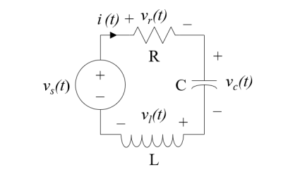
R i(t) + L d i(t)/dt + 1/C  dx = vs(t)
d 2 i(t) / dt 2 + R/L d i(t)/dt + 1/LC i(t) = 1/L d vs(t) /dt
Most circuits with one inductor and capacitor are not easy to analyse hence every voltage and current in the circuit is the solution to the differential equation given by

The roots of the characteristic equation whether the complementary solution wiggles.

 , s1 and s2 are real and not equal then

The solution is overdamped.
 are complex then

The solution is underdamped.
If  s1 and s2 are real and equal

The solution is critically damped.
Parallel RLC circuit
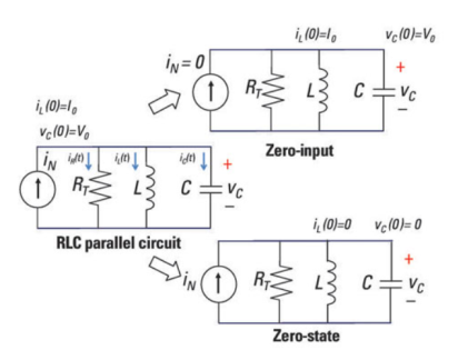
The left diagram shows an input with initial inductor current Io and capacitor voltage Vo. The top-right diagram shows the input current source I N set equal to zero. The bottom-right diagram shows the initial conditions Io and Vo set equal to zero which lets you obtain the zero state response.
Using KCL we get
iN(t) =iR(t) +iC(t) +iL(t)
The resistor current iR(t) is based on the old, reliable Ohm’s law:
i R(t) = v(t)/R
The element constraint for an inductor is given as
v(t) = L di(t) /dt
The current iL(t) is the inductor current, and L is the inductance. This constraint means a changing current generates an inductor voltage. If the inductor current doesn’t change, there’s no inductor voltage, implying a short circuit.
Parallel devices have the same voltage v(t).The inductor voltage v(t) equal to the capacitor voltage to obtain capacitor current iC(t):
Ic(t) = C dv(t)/dt = LC d2 iL(t)/dt 2
Now substitute v(t) = L diL(t)/dt into Ohm’s law, because same voltage appears across the resistor and inductor:
i R (t) = (L/R) d i L(t) /dt
Substitute the values of iR(t) and iC(t) into the KCL equation to get currents in terms of the inductor current:
i N (t) = LC d 2 i L (t) / dt 2 + (L/R) d iL(t)/dt + i L(t)
The RLC parallel circuit is described by a second-order differential equation, so the circuit is a second-order circuit.
The unknown is the inductor current iL(t).
v T(t) = LC d 2 vc(t)/ dt2 + RC dvc(t)/dt + vc (t)
For a parallel circuit the second-order and homogeneous differential equation is given in terms of the inductor current:
0 = d 2 iL /dt 2 + (1/RC) d iL(t)/dt + (1/LC) iL(t)
k 2 + 1/RC k + !?LC =0 -- k1,k2 = - 1/2RC  ½
½  [ (1/RC) 2 – 4/LC]
The preceding equation gives you three possible cases under the radical:
Case 1: [ (1/RC) 2 – 4/LC ] >0 two different roots α 1 and α 2.
Case 2: [(1/RC) 2 – 4/LC] =0 two equal roots (α1=α2)
Case 3: [1/RC) 2 – 4/LC] <0 two complex conjugate roots (α1  j β)
j β)
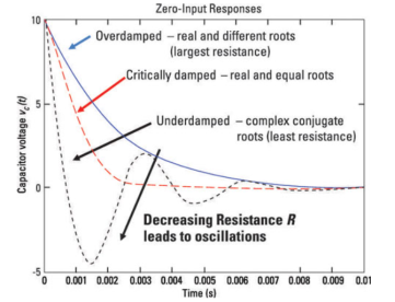
When k1 and k2 are known, we obtain the zero-input response iZI(t). The solution gives you

To find the constants c1 and c2 by using the results found in the RLC series circuit, which are given as
c 1 = k2 Vo – Io/C / k2 – k1
c2 = -k1 Vo + Io/C / k2 -k1
Apply duality to the preceding equation by replacing the voltage, current, and inductance with their duals (current, voltage, and capacitance) to get c1 and c2 for the RLC parallel circuit:
c 1 = k2 Io – Vo/L / k2 -k1
c2 = -k1Io + Vo/L / k2 -k1
For RC circuit
Ic = 0A when t< to
Vc = 0V when t < to
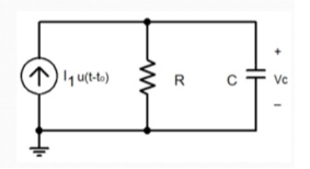
Because I1 =0A (replace it with open circuit)
Find the final condition of the voltage across the capacitor
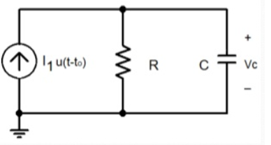
Ic =0A when ͂ ∞ s
Vc = VR = I1R when ~ ∞ s
RL circuit:
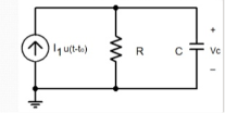
In the time between to and t=∞ s, the capacitor stores energy and currents flow through R and C.
Vc = VR
Ic = C dVc/dt
IR = VR/R
IR + Ic -I1 =0
Vc/R + C dVc/dt – I1 =0
Vc (t) = R I1 [ 1 – e – t-to/ τ] τ=RC
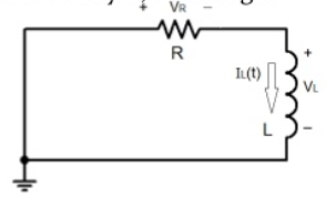
Initial condition is not important as the magnitude of the voltage source in the circuit is equal to 0V when t≤ to.
Since the voltage source has only been turned on at t=to the circuit at t ≤ to is shown below:
As the inductor has not stored any energy because no power source has been connected to the circuit all voltages and currents are equal to zero.

So, the final condition of the inductor current needs to be calculated after the voltage source has switched on.
Replace L with a short circuit and calculate IL (∞) .
Final condition:
VL(∞) = 0V
I L (∞) = IR
I R = V1 /R
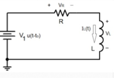
RL circuit
-V1 + VL + VR =0
I L = I R = V R /R
VL = L dIL/dt
DIL/dt + R I R -V1 =0
DIL/dt + R/L IL – V1/L =0
Consider the following example:
The equation of motion of the body mass is
m. d 2 x/ dt 2 + c . Dx /dt + k.x = F -------------------------(1)
Where:
m [kg] – mass
k [N/m] – spring constant (stiffness)
c [N⋅s/m] – damping coefficient
F [N] – external force acting on the body
x [m] – displacement of the body
The free response of a system is the solution of the describing differential equation of the system, when the input is zero.
In our case the input into the system is the force F [N]. Therefore, in order to verify the free response of the system we have to solve the differential equation:
M . d 2 x / d t2 + c. Dx /dt + k.x =0 -----------------------------(2)
To be able to see the free response, we need an initial condition. For our example we are going to set the initial conditions:
x(0)=0.4
v(0)=0
The free response of the mass spring-damper system will be the variation in time of the displacement x [m].
To integrate equation (2),write it in the following form:
d 2 x/ dt2 = 1/m . ( -c dx/dt – k.x)
Equation (3) is modelled and integrated in Xcos
The general equation of a free response system has the differential equation in the form:
 d i x / d t i = 0 -----------------------------(4)
Forced response of a system
The forced response of a system is the solution of the differential equation describing the system, taking the impact of the input. If the input is force F [N] then
m . d 2 x / d t 2 + c . Dx /dt + k.x = F(t)
To visualise the forced system response of a system, all the initial conditions must be zero:
x(0)=0
v(0)=0
The forced response of the mass spring-damper system will be the variation in time of the displacement x [m].
d 2 x / d t2 = 1/m . (F-c . Dx/dt – k.x )
We can reuse the Xcos model from the free system response, the only differences being that there is an input step force added and the initial condition of the position is 0 m.
Let us assume, the capacitor is initially unchanged, and the switch S is closed at time t = 0. After closing the switch, electric current i(t) starts flowing through the circuit. Applying Kirchhoff Voltage Law in that single mesh circuit, we get,
v = R i(t) + 1/C  dt
dt
Differentiating both sides with respect to time t, we get
R d i(t) /dt + i(t) /C =0
R di(t)/dt = - i(t)/C
-RC d i(t)/i(t) = dt
d i(t)/ i(t) = -1/R C dt
Integrating both side we get,
 = -1/RC dt
Log e i(t) + log e i(k) = -t/RC
Now, at t = 0, the capacitor behaves as short circuit, so, just after closing the switch, the current through the circuit will be,
Io = V/R
Now, putting this value in equation (i) we get,
k V/R = e 0
k = R/V
Putting the value of k at equation (i) we get,
I(t) = V/R e -t/RC
Now, if we put t = RC in the final expression of circuit current i(t), we get,
I t=RC = V/R e-1
= 0.367 V/R = 0.367 Io or 36.7 % of Io
From the above mathematical expression it is clear that RC is the time in second during which the current in a charging capacitor diminishes to 36.7 percent from its initial value. Initial value means, current at the time of switching on the unchangedcapacitor.
This term is quite significant in analyzing behaviour of capacitive as well as inductive circuit. This term is known as time constant.
So, time constant is the duration in seconds during which the current through a capacities circuit becomes 36.7 percent of its initial value. This is numerically equal to the product of resistance and capacitance value of the circuit. Time constant is normally denoted by τ (tau). So,
In complex RC circuit, time constant will be product of equivalent resistance and capacitance of circuit.
If we plot current i(t).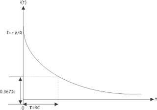
At t = 0, the current through the capacitor circuit is
Io = V/R
At t = RC, the current through the capacitor is
0.367 Io = 0.367 V/R
Example : 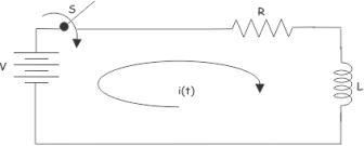
Applying KVL in the above circuit. We get,
V = R i(t) + L d i(t)/dt
The equation can also be solved using Laplace transform technique. For that we have to take Laplace transform of the equation at both sides,
V/s = L [ s I(s) – i(0+) ] + R I(s)
V/s = L s I(s) + R I(s)
I(s) = V / s(Ls + R)
Hence, in this equation.
I(0+) =0
Since, current just after switch is on, current through the inductor will be zero.
Now,
I(s) = No / Ls (s + R/L) = Vo/L . 1/ s(s + R/L)
Taking inverse Laplace of the above equation, we get,
i(t) = No/R [ 1 – e -Rt/L]
Now, if we put,
t = L/R
We get,
i(L/R) = Vo/R [ 1- e-1 ] = 0.633 Vo/R
So, at RL circuit, at time = L/R sec the current becomes 63.3% of its final steady state value. The L/R is known as time constant of an RL circuit . Let us plot the current of inductor circuit.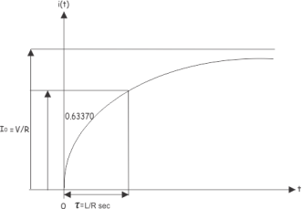
The time constant of an RL circuit is the ratio of inductance to resistance of the circuit.
Scroll back to top
- Transient response
- Steady state response
The response of control system in time domain is shown in the following figure.
Here, both the transient and the steady states are indicated in the figure. The responses corresponding to these states are known as transient and steady state responses.
Mathematically, we can write the time response c(t) as
c(t)=ctr(t)+css(t)
Where,
- ctr(t) is the transient response
- css(t) is the steady state response
Transient Response
After applying input to the control system, output takes certain time to reach steady state. So, the output will be in transient state till it goes to a steady state. Therefore, the response of the control system during the transient state is known as transient response.
The transient response will be zero for large values of ‘t’. Ideally, this value of ‘t’ is infinity and practically, it is five times constant.
Mathematically, we can write it as
Limt→∞ctr(t)=0
Steady state Response
The part of the time response that remains even after the transient response has zero value for large values of ‘t’ is known as steady state response. This means, the transient response will be zero even during the steady state.
Find the transient and steady state terms of the time response of the control system
c(t)=10+5e−t
Here, the second term 5e−t will be zero as t denotes infinity.
So, this is the transient term.
And the first term 10 remains even as t approaches infinity. So, this is the steady state term.
References:
- Network theory by A.V Bakshi, U.A Bakshi
- Network Theory Analysis and Synthesis by Smarajit Ghosh
- Networks: An introduction by Mark Newman
- Network Theory (Bput) book by Satpathy