Module 3
Sinusoidal steady state analysis
The phase of an alternating quantity at any instant in time can be represented by a phasor diagram,
Therefore, phasor diagrams can be thought of as “functions of time”.
A complete sine wave can be constructed by a single vector rotating at an angular velocity of ω = 2πƒ, where ƒ is the frequency of the waveform. Then a Phasor is a quantity that has both “Magnitude” and “Direction”.
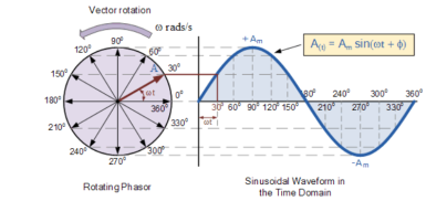
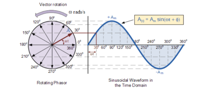
As the single vector rotates in an anti-clockwise direction, its tip at point A will rotate one complete revolution of 360o or 2π representing one complete cycle.
If the length of its moving tip is transferred at different angular intervals in time to a graph as shown above, a sinusoidal waveform would be drawn starting at the left with zero time.
Each position along the horizontal axis indicates the time that has elapsed since zero-time, t = 0.
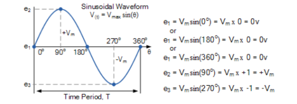
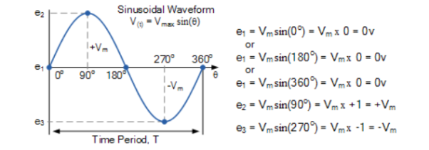
When the vector is horizontal the tip of the vector represents the angles at 0o, 180o and at 360o.
Likewise, when the tip of the vector is vertical it represents the positive peak value, ( Am ) at 90o or π/2 and the negative peak value, ( -Am ) at 270o or 3π/2. Then the time axis of the waveform represents the angle either in degrees or radians through which the phasor has moved.
Hence, a phasor represents scaled voltage or current value of a rotating vector which is “frozen” at some point in time, t.
Sometimes when analysing alternating waveforms we need to know the position of the phasor, representing the Alternating Quantity at some particular instant in time especially when we want to compare two different waveforms on the same axis.
For example, voltage and current. We have assumed in the waveform above that the waveform starts at time t = 0 with a corresponding phase angle in either degrees or radians.
But if a second waveform starts to the left or to the right of this zero point or we want to represent in phasor notation the relationship between the two waveforms then we need to take into account the phase difference, Φ of the waveform.
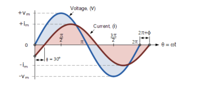
Consider the diagram as shown below
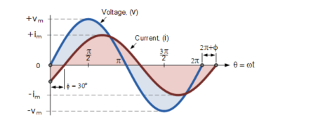
The generalised mathematical expression to define these two sinusoidal quantities will be written as:
v(t) = Vm sin(wt) -------------------(1)
i(t) = Im sin(wt-ɸ) ----------------------------(2)
The current, i is lagging the voltage, v by angle Φ. So, the difference between the two phasors representing the two sinusoidal quantities is angle Φ .
Phasor Diagram:
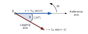
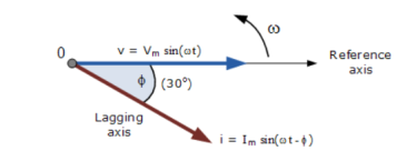
The phasor diagram is drawn corresponding to time t = 0 on the horizontal axis. The lengths of the phasors are proportional to the values of the voltage, (V ) and the current, ( I ) at the instant in time that the phasor diagram is drawn.
The current phasor lags the voltage phasor by the angle, Φ, as the two phasors rotate in an anticlockwise direction, therefore the angle, Φ is also measured in the same anticlockwise direction.
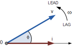
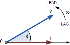
If however, the waveforms are frozen at time, t = 30o, the corresponding phasor diagram would look like the one shown below. Once again, the current phasor lags behind the voltage phasor as the two waveforms are of the same frequency.
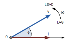
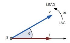
However, as the current waveform is now crossing the horizontal zero axis line at this instant in time the current phasor as our new reference and correctly say that the voltage phasor is “leading” the current phasor by angle, Φ. Either way, one phasor is designated as the reference phasor and the other phasors will be either leading or lagging with respect to the reference.
Impedance
Impedance consists of real part resistance and imaginary part reactance. The symbol for impedance is the Z symbol, and the symbol for admittance is the Y symbol.
Z = R =jX
Z = Impedance in Ohms
X = Reactance in Ohms
R = Resistance in Ohms
Y = 1/Z = Z -1 = 1/ R +jX
Therefore, Y = 1/ R 2 + X2 . (R – jX)
Admittance
It is the complex number as impedance which is having real part conductance (G) and imaginary part Susceptance (B)
Y = G +jB
Y -> Admittance in Siemens
G -> Conducatnce in Siemens= R/ R2 + X2
B -> Susceptance in Siemens = - X / R2 + X2
|Y| = [ G2 + B2] | ½ = 1/ [ R2 + X 2] ½
< Y = arctan (B/G) = arctan (-X/R)
Admittance of series circuit
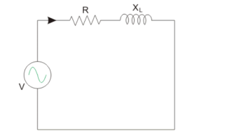
When a circuit consist of Resistance and Inductance reactance in series is considered as shown below.
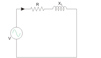
Y = 1/Z = Z -1 = 1/ R + j XL
XL ----- Inductive reactance in Ω.
Y = 1/R + j XL x ( R – j XL/ R – j XL) = R – jXL/ R 2 + X L 2
Y = R / R 2 + X L 2 – j XL / R2 + X 2 L = G – j B L =  G 2 + B L 2
The circuit consist of Resistance and Capacitive reactance in series is considered as shown below.
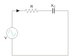
Y = 1/Z = Z -1 = 1/ R – j Xc
Xc = Capacitive reactance in Ω.
Y = 1/ R – j X L x ( R + j Xc / R + j Xc) = R + j Xc/ R2 + X C 2
Y = R / R 2 + Xc 2 + j X c / R 2 + Xc 2 = G + j Bc =  G2 + Bc 2
Bc = Capacitive susceptance in mho.
A sinewave is defined by the trigonometric sine function. The waveform repeats every 2p radians and is symmetrical about the voltage axis. The voltage and current exhibit cyclic behaviour referred as alternating current. The equation is represented as :
V(Ɵ) = Vpk . Sin(Ɵ) -----------------------(1)
There are several ways in which the amplitude of the sinewave is referenced say peak voltage, peak-to-peak voltage, average voltage, and root mean square voltage.
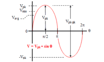
Average voltage:
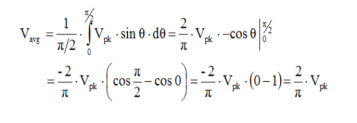
Vavg is calculated by taking the average of the voltage in appropriate chosen interval. For the first quarter cycle that is 0 to π/2 radians.

RMS voltage:
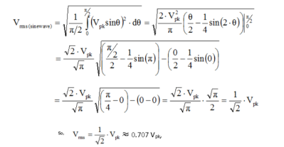
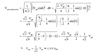
As the name implies, Vrms is calculated by taking the square root of the mean average of the square of the voltage in an appropriately chosen interval.
Form factor:
For a sinusoidal signal of peak voltage Vm it is given by :
Form factor of a sinusoidal signal = Vrms /Vav = 0.707 Vm / 0.637 Vm = 1.11
Peak Factor (Or Crest factor):
It is defined as the ratio of maximum value to the R.M.S value of an alternating quantity.
Peak factor of a sinusoidal signal=Vmax/Vrms =Vmax/(0.707 Vm) =1.414
Average Power:
As the instantaneous power is the power at any instant of time, then:
p = v x i
Where v = Vm sin(wt+Ɵv)
i = Im sin(wt+Ɵi)
p = Vm sin(wt+Ɵv) Im sin(wt+Ɵi)
p= Vm Im [sin(wt+ Ɵv) sin(wt +Ɵi)]
p=Vm Im/2[cos Ɵ -cos(2wt+Ɵ)]
= Vm Im/2 = Vm/ x Im/
x Im/ =Vrms x Irms (W)
Where V and I are the root-mean-squared values of sinusoidal waveforms.
Complex power:
It is the product of the rms voltage phasor and the complex conjugate of the rms current phasor.
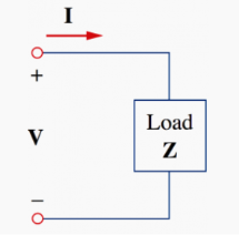
The voltage and current phasor
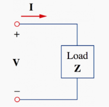
Given the phasor form V = Vm< Ɵv and I = Im<Ɵi of voltage v(t) and current i(t) the complex power S absorbed by the AC load is the product of the voltage and the complex conjugate of the current.
S = ½ V I * assuming the passive sign convention.
S = Vrms Irms *
Where Vrms = V/ = Vrms
  Ɵv and
Irms = I/ = Irms <Ɵi
S = Vrms Irms < Ɵv – Ɵi = Vrms Irms cos(Ɵv – Ɵi) +jVrms Irms sin(Ɵv – Ɵi).
The load impedance Z may be written as:
Z=V/I = Vrms/Irms = Vrms/Irms < Ɵv -Ɵi
Thus Vrms = Z x Irms
S = I 2 rms Z = V 2 rms / Z* = Vrms Irms *
Since I2 rms (R+jX) = P=jQ
Where P and Q are real and imaginary parts of the complex power that is
P = Re(S) = I2 rms R
Q = Im(S) = I2 rms X
Complex Power = S = P +jQ = Vrms (Irms) * = Vrms Irms < Ɵv - Ɵi
The three -phase system can be used as three single phase line so it can act as three single phase system.
The three- phase generation and single- phase generation is same in the generator except for the arrangement of coil in the generator to get a phase difference of 120o
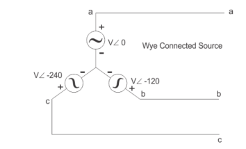
Three voltage sources are connected to form a three- phase circuit present inside the generator. The generator is having three voltage sources which are acting together in 120o phase difference. If we can arrange three single-phase circuit with 120o phase difference, then it will become a three -phase circuit.
In three phase circuit, connections can be given in two types:
- Star connection
- Delta connection
Star Connection
In star connection, there is four wire, three wires are phase wire and fourth is neutral which is taken from the star point. Star connection is preferred for long distance power transmission because it is having the neutral point.
When equal current will flow through all the three phases, then it is called as balanced current. And when the current will not be equal in any of the phase, then it is unbalanced current.
In balanced condition there will be no current flowing through the neutral line and hence there is no use of the neutral terminal. But when there will be unbalanced current flowing in the three- phase circuit, neutral is having a vital role. It will take the unbalanced current through to the ground and protect the transformer. Unbalanced current affects transformer and cause damage to the transformer hence star connection is preferred for long distance transmission.
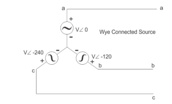
In star connection, the line voltage is √3 times of phase voltage. Line voltage is the voltage between two phases in three phase circuit and phase voltage is the voltage between one phase to the neutral line. And the current is same for both line and phase.
E line =  Ephase and I line = I phase
Delta Connection
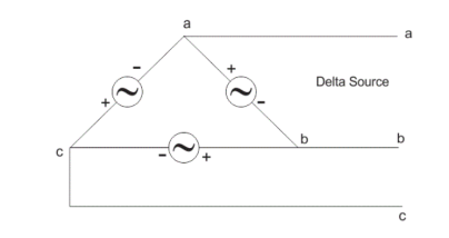
In delta connection, there is three wires alone and no neutral terminal is taken. Normally delta connection is preferred for short distance due to the problem of unbalanced current in the circuit. The figure is shown below for delta connection. In the load station, ground can be used as neutral path if required.
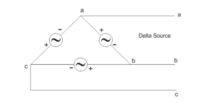
In delta connection, the line voltage is the same as that of phase voltage. And the line current is √3 times of phase current. It is shown as expression below,
E line = E phase and I line =  3 I Phase
An electric circuit is said to be a coupled circuit when there exists a mutual inductance between the coils or inductors present in the circuit. Coil is nothing but the series combination of resistor and inductor. In the absence of resistor, coil becomes inductor.
Mutual Inductance
If the flux produced by one coil links with the other coil, placed sufficiently close to the first coil, then due to the change in the flux produced by first coil, there is induced e.m.f. In second coil. Such induced e.m.f. In the second coil is called mutually induced e.m.f.
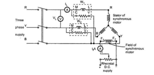
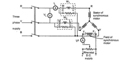
Let coil1 has N1 turns, while coil 2 has N2 turns. The current flowing through coil 1 is i1. Due to this current, the flux produced in coil 1 is Φ1. The part of this flux links with coil 2. This flux is called mutual flux.
It is denoted by Φ21 a sit is a part of flux Φ1 linking with coil 2. When current through coil 1 changes, the flux produced in coil 1 i.e. Φ1 changes. Thus, flux associated with coil 2 i.e. Φ21 changes. So according to the Faraday’s law, there will be induced e.m.f. In coil 2.
According to Faraday’s law, the magnitude of the induced e.m.f. Is given by,
V2 = N2 (dΦ21/dt) ……………..(1)
Now, Φ21 = Φ21/i x i
If the permeability of the surroundings is assumed constant, then Φ21 α i1 and hence Φ21/i is constant.
... Rate of change of Φ21 = Φ21/i x Rate of change of i1
... dΦ21/dt = Φ21/i1 x di1/dt ……………(2)
Putting value of dΦ21/dt in equation (1), the magnitude of the induced e.m.f. Can be written by as,
V2 = N2 (Φ21/i1 . di1/dt)
... V2 = (N2 Φ21/i1) di1/dt ……………(3)
Here the constant term (N2 Φ21/i1)is defined as coefficient of mutual inductance and it is denoted by M.
... M = N2 Φ21/ i1 ……………(4)
Then equation (3) can be written as,
... V2 = M di1/dt ………….(5)
Thus equation (5) indicates the magnitude of the e.m.f. Induced in coil 2 as a function of change in current in coil 1.
Dot convention is a technique, which gives the details about voltage polarity at the dotted terminal. While writing KVL equations.
- If the current enters at the dotted terminal of one coil or inductor, then it induces a voltage at another coil or inductor, which is having positive polarity at the dotted terminal.
- If the current leaves from the dotted terminal of one coil or inductor, then it induces a voltage at another coil or inductor, which is having negative polarity at the dotted terminal.
Classification of Coupling
We can classify coupling into the following two categories.
- Electrical Coupling
- Magnetic Coupling
Electrical Coupling
Electrical coupling occurs, when there exists a physical connection between two coils or inductors. This coupling can be of either aiding type or opposing type. It is based on whether the current enters at the dotted terminal or leaves from the dotted terminal.
Coupling of Aiding type
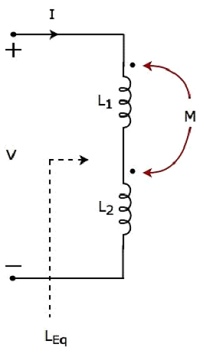
Consider the following electric circuit, which is having two inductors that are connected in series.
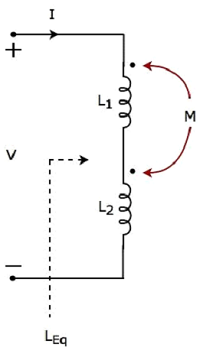
Since the two inductors are connected in series, the same current I flow through both inductors having self-inductances L1 and L2.
In this case, the current, I enter at the dotted terminal of each inductor. Hence, the induced voltage in each inductor will be having positive polarity at the dotted terminal due to the current flowing in another coil.
Apply KVL around the loop of the above electric circuit or network.
V – L1 dI/dt – M dI/dt – L2 dI/dt – M dI/dt =0
V = L1 dI/dt + L2 dI/dt + 2M dI/dt
V = (L1+L2+2M) dI/dt
The above equation is of the form:
V = L eq dI/dt
Therefore, the equivalent inductance of series combination of inductors
L eq = L1+L2+2M
Coupling of Opposing type
Consider the following electric circuit, which is having two inductors that are connected in series.
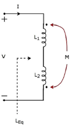
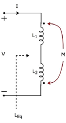
The current I enter at the dotted terminal of the inductor having an inductance of L1. Hence, it induces a voltage in the other inductor having an inductance of L2. So, positive polarity of the induced voltage is present at the dotted terminal of this inductor.
In the above circuit, the current I leaves from the dotted terminal of the inductor having an inductance of L2. Hence, it induces a voltage in the other inductor having an inductance of L1. So, negative polarity of the induced voltage is present at the dotted terminal of this inductor.
Apply KVL around the loop of the above electric circuit or network.
V = L1 dI/dt + L2 dI/dt - 2M dI/dt
V = (L1+L2-2M) dI/dt
V = Leq dI/dt
Leq = L1 + L2 -M
Magnetic Coupling
Magnetic coupling occurs, when there is no physical connection between two coils (or inductors). This coupling can be of either aiding type or opposing type. It is based on whether the current enters at the dotted terminal or leaves from the dotted terminal.
Coupling of Aiding type
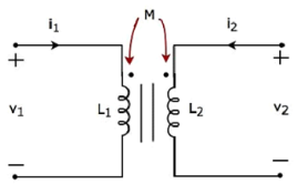
Consider the following electrical equivalent circuit of transformer. It is having two coils, and these are called as primary and secondary coils.
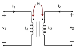
Apply KVL around primary coil
v 1 – L1 di/dt -M di2/dt =0
v1 = L1 di/dt + M di2/dt
Apply KVL around secondary coil
v 2 – L2 di2/dt – M di1/dt =0
v2 = L2 di2/dt + M di1/dt
In Equation 1 and Equation 2, the self-induced voltage and mutually induced voltage have the same polarity. Hence, the above transformer circuit is an example of magnetic coupling, which is of aiding type.
Coupling of Opposing Type
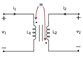
Consider the following electrical equivalent circuit of transformer.
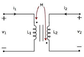
Apply KVL around primary coil
v 1 – L1 di1/dt – M di2/dt =0
v1 = L1 di1/dt + M di2/dt ----------------------------(1)
Apply KVL around the secondary coil
v 2 – L2 di2/dt – M di2/dt
v2 = L2 di2/dt + M di2/dt ----------------------------(2)
In Equation 3 and Equation 4, self-induced voltage and mutually induced voltage are having opposite polarity. Hence, the above transformer circuit is an example of magnetic coupling, which is of opposing type.
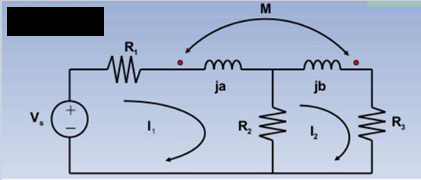
Example:
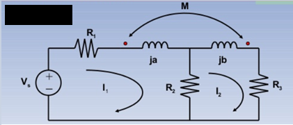
Solution:
KVL I1:
(R1 + R2 + ja)I1 – M I2 = Vs -----------------(1)
KVL I2:
-R2I1 + (R2+R3 +jb) I2 – M I1 =0 ………………………(2)

KVL I1 :
(R1 + ja +jb)I1 -jbI2 + M(I1-I2) + MI1 = Vs -----------(1)
KVL I2:
-jbI1 + (R2+jb-jc) I2 – M I1 =0 -----------------------------(2)
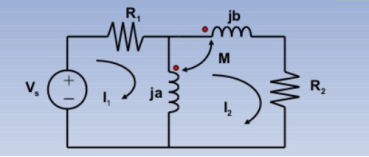
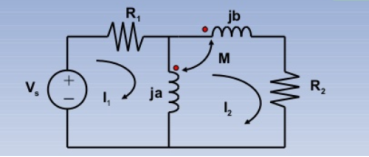
KVL I1 : (R1 +ja) I1 -jaI2 +MI2 = Vs -------------------(1)
KVL I2 : -jaI1 +(R2 + ja+jb) I2 – MI2 _ M(I2-I1) =0 ----------(2)
Ideal transformer can be defined as the transformer which id free of all types of losses. It is an imaginary transformer that has no core loss, no ohmic resistance and no leakage flux. It has the following characteristic:
- The resistance of their primary and secondary winding becomes zero.
- The core of the ideal transformer has infinite permeability.
- The leakage flux of the transformer becomes zero that is the whole of the flux induces into the core of the transformer links with their primary and secondary winding.
- The ideal transformer has 100% efficiency, the transformer is free from hysteresis and eddy current loss.
- In an ideal transformer there is no power loss. Therefore, output power is equal to input power.
E2 I2 cos ɸ = E1 I1 cos ɸ
E2 I2 = E1 I1
E2 / E1 = I1/I2
The transformation ratio is given by
V2/V1 = E2/E1 = N2/N1 = I1/I2 =K
Behaviour of Ideal Transformer:
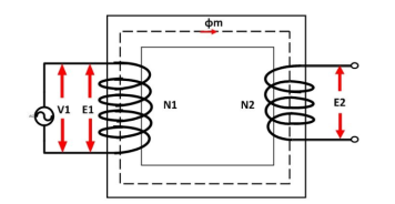
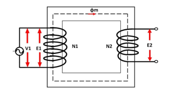
The voltage source V1 is applied across the primary winding of the transformer. The secondary winding is kept open. The N1 and N2 are the numbers of turns of their primary and secondary winding.
The current Im is the magnetizing current flows through the primary winding of the transformer. The magnetizing current produces the flux φm in the core of the transformer.
The flux link with the primary winding induces the emf E1 because of self-induction. The direction of the induced emf is inversely proportional to the applied voltage V1. The emf E2 induces in the secondary winding of the transformer because of mutual induction.
Phasor diagram of ideal transformer:
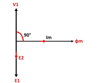
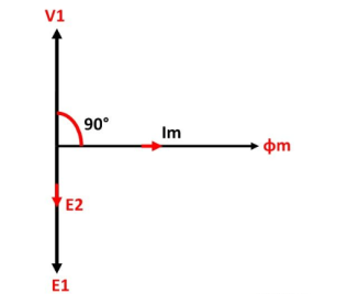
The phasor diagram of the ideal transformer is shown in the figure. As the coil of the primary transformer is purely inductive the magnetizing current induces in the transformer lag 90º by the input voltage V1.
The E1 and E2 are the emf induced in the primary and secondary winding of the transformer. The direction of the induced emf inversely proportional to the applied voltage.
References:
- Network theory by A.V Bakshi, U.A Bakshi
- Network Theory Analysis and Synthesis by Smarajit Ghosh
- Networks: An introduction by Mark Newman
- Network Theory (Bput) book by Satpathy
Module 3
Sinusoidal steady state analysis
The phase of an alternating quantity at any instant in time can be represented by a phasor diagram,
Therefore, phasor diagrams can be thought of as “functions of time”.
A complete sine wave can be constructed by a single vector rotating at an angular velocity of ω = 2πƒ, where ƒ is the frequency of the waveform. Then a Phasor is a quantity that has both “Magnitude” and “Direction”.
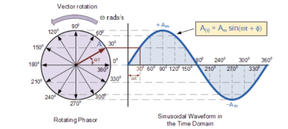
As the single vector rotates in an anti-clockwise direction, its tip at point A will rotate one complete revolution of 360o or 2π representing one complete cycle.
If the length of its moving tip is transferred at different angular intervals in time to a graph as shown above, a sinusoidal waveform would be drawn starting at the left with zero time.
Each position along the horizontal axis indicates the time that has elapsed since zero-time, t = 0.
When the vector is horizontal the tip of the vector represents the angles at 0o, 180o and at 360o.
Likewise, when the tip of the vector is vertical it represents the positive peak value, ( Am ) at 90o or π/2 and the negative peak value, ( -Am ) at 270o or 3π/2. Then the time axis of the waveform represents the angle either in degrees or radians through which the phasor has moved.
Hence, a phasor represents scaled voltage or current value of a rotating vector which is “frozen” at some point in time, t.
Sometimes when analysing alternating waveforms we need to know the position of the phasor, representing the Alternating Quantity at some particular instant in time especially when we want to compare two different waveforms on the same axis.
For example, voltage and current. We have assumed in the waveform above that the waveform starts at time t = 0 with a corresponding phase angle in either degrees or radians.
But if a second waveform starts to the left or to the right of this zero point or we want to represent in phasor notation the relationship between the two waveforms then we need to take into account the phase difference, Φ of the waveform.
Consider the diagram as shown below
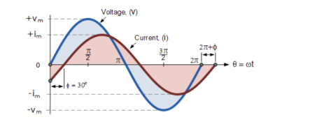
The generalised mathematical expression to define these two sinusoidal quantities will be written as:
v(t) = Vm sin(wt) -------------------(1)
i(t) = Im sin(wt-ɸ) ----------------------------(2)
The current, i is lagging the voltage, v by angle Φ. So, the difference between the two phasors representing the two sinusoidal quantities is angle Φ .
Phasor Diagram:
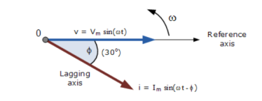
The phasor diagram is drawn corresponding to time t = 0 on the horizontal axis. The lengths of the phasors are proportional to the values of the voltage, (V ) and the current, ( I ) at the instant in time that the phasor diagram is drawn.
The current phasor lags the voltage phasor by the angle, Φ, as the two phasors rotate in an anticlockwise direction, therefore the angle, Φ is also measured in the same anticlockwise direction.
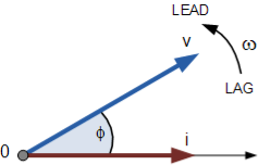
If however, the waveforms are frozen at time, t = 30o, the corresponding phasor diagram would look like the one shown below. Once again, the current phasor lags behind the voltage phasor as the two waveforms are of the same frequency.
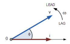
However, as the current waveform is now crossing the horizontal zero axis line at this instant in time the current phasor as our new reference and correctly say that the voltage phasor is “leading” the current phasor by angle, Φ. Either way, one phasor is designated as the reference phasor and the other phasors will be either leading or lagging with respect to the reference.
Impedance
Impedance consists of real part resistance and imaginary part reactance. The symbol for impedance is the Z symbol, and the symbol for admittance is the Y symbol.
Z = R =jX
Z = Impedance in Ohms
X = Reactance in Ohms
R = Resistance in Ohms
Y = 1/Z = Z -1 = 1/ R +jX
Therefore, Y = 1/ R 2 + X2 . (R – jX)
Admittance
It is the complex number as impedance which is having real part conductance (G) and imaginary part Susceptance (B)
Y = G +jB
Y -> Admittance in Siemens
G -> Conducatnce in Siemens= R/ R2 + X2
B -> Susceptance in Siemens = - X / R2 + X2
|Y| = [ G2 + B2] | ½ = 1/ [ R2 + X 2] ½
< Y = arctan (B/G) = arctan (-X/R)
Admittance of series circuit
When a circuit consist of Resistance and Inductance reactance in series is considered as shown below.
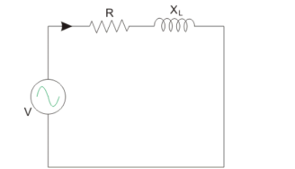
Y = 1/Z = Z -1 = 1/ R + j XL
XL ----- Inductive reactance in Ω.
Y = 1/R + j XL x ( R – j XL/ R – j XL) = R – jXL/ R 2 + X L 2
Y = R / R 2 + X L 2 – j XL / R2 + X 2 L = G – j B L =  G 2 + B L 2
The circuit consist of Resistance and Capacitive reactance in series is considered as shown below.
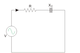
Y = 1/Z = Z -1 = 1/ R – j Xc
Xc = Capacitive reactance in Ω.
Y = 1/ R – j X L x ( R + j Xc / R + j Xc) = R + j Xc/ R2 + X C 2
Y = R / R 2 + Xc 2 + j X c / R 2 + Xc 2 = G + j Bc =  G2 + Bc 2
Bc = Capacitive susceptance in mho.
A sinewave is defined by the trigonometric sine function. The waveform repeats every 2p radians and is symmetrical about the voltage axis. The voltage and current exhibit cyclic behaviour referred as alternating current. The equation is represented as :
V(Ɵ) = Vpk . Sin(Ɵ) -----------------------(1)
There are several ways in which the amplitude of the sinewave is referenced say peak voltage, peak-to-peak voltage, average voltage, and root mean square voltage.
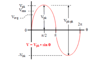
Average voltage:
Vavg is calculated by taking the average of the voltage in appropriate chosen interval. For the first quarter cycle that is 0 to π/2 radians.
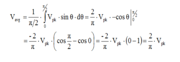

RMS voltage:
As the name implies, Vrms is calculated by taking the square root of the mean average of the square of the voltage in an appropriately chosen interval.
Form factor:
For a sinusoidal signal of peak voltage Vm it is given by :
Form factor of a sinusoidal signal = Vrms /Vav = 0.707 Vm / 0.637 Vm = 1.11
Peak Factor (Or Crest factor):
It is defined as the ratio of maximum value to the R.M.S value of an alternating quantity.
Peak factor of a sinusoidal signal=Vmax/Vrms =Vmax/(0.707 Vm) =1.414
Average Power:
As the instantaneous power is the power at any instant of time, then:
p = v x i
Where v = Vm sin(wt+Ɵv)
i = Im sin(wt+Ɵi)
p = Vm sin(wt+Ɵv) Im sin(wt+Ɵi)
p= Vm Im [sin(wt+ Ɵv) sin(wt +Ɵi)]
p=Vm Im/2[cos Ɵ -cos(2wt+Ɵ)]
= Vm Im/2 = Vm/ x Im/
x Im/ =Vrms x Irms (W)
Where V and I are the root-mean-squared values of sinusoidal waveforms.
Complex power:
It is the product of the rms voltage phasor and the complex conjugate of the rms current phasor.
The voltage and current phasor
Given the phasor form V = Vm< Ɵv and I = Im<Ɵi of voltage v(t) and current i(t) the complex power S absorbed by the AC load is the product of the voltage and the complex conjugate of the current.
S = ½ V I * assuming the passive sign convention.
S = Vrms Irms *
Where Vrms = V/ = Vrms
  Ɵv and
Irms = I/ = Irms <Ɵi
S = Vrms Irms < Ɵv – Ɵi = Vrms Irms cos(Ɵv – Ɵi) +jVrms Irms sin(Ɵv – Ɵi).
The load impedance Z may be written as:
Z=V/I = Vrms/Irms = Vrms/Irms < Ɵv -Ɵi
Thus Vrms = Z x Irms
S = I 2 rms Z = V 2 rms / Z* = Vrms Irms *
Since I2 rms (R+jX) = P=jQ
Where P and Q are real and imaginary parts of the complex power that is
P = Re(S) = I2 rms R
Q = Im(S) = I2 rms X
Complex Power = S = P +jQ = Vrms (Irms) * = Vrms Irms < Ɵv - Ɵi
The three -phase system can be used as three single phase line so it can act as three single phase system.
The three- phase generation and single- phase generation is same in the generator except for the arrangement of coil in the generator to get a phase difference of 120o
Three voltage sources are connected to form a three- phase circuit present inside the generator. The generator is having three voltage sources which are acting together in 120o phase difference. If we can arrange three single-phase circuit with 120o phase difference, then it will become a three -phase circuit.
In three phase circuit, connections can be given in two types:
- Star connection
- Delta connection
Star Connection
In star connection, there is four wire, three wires are phase wire and fourth is neutral which is taken from the star point. Star connection is preferred for long distance power transmission because it is having the neutral point.
When equal current will flow through all the three phases, then it is called as balanced current. And when the current will not be equal in any of the phase, then it is unbalanced current.
In balanced condition there will be no current flowing through the neutral line and hence there is no use of the neutral terminal. But when there will be unbalanced current flowing in the three- phase circuit, neutral is having a vital role. It will take the unbalanced current through to the ground and protect the transformer. Unbalanced current affects transformer and cause damage to the transformer hence star connection is preferred for long distance transmission.
In star connection, the line voltage is √3 times of phase voltage. Line voltage is the voltage between two phases in three phase circuit and phase voltage is the voltage between one phase to the neutral line. And the current is same for both line and phase.
E line =  Ephase and I line = I phase
Delta Connection
In delta connection, there is three wires alone and no neutral terminal is taken. Normally delta connection is preferred for short distance due to the problem of unbalanced current in the circuit. The figure is shown below for delta connection. In the load station, ground can be used as neutral path if required.
In delta connection, the line voltage is the same as that of phase voltage. And the line current is √3 times of phase current. It is shown as expression below,
E line = E phase and I line =  3 I Phase
An electric circuit is said to be a coupled circuit when there exists a mutual inductance between the coils or inductors present in the circuit. Coil is nothing but the series combination of resistor and inductor. In the absence of resistor, coil becomes inductor.
Mutual Inductance
If the flux produced by one coil links with the other coil, placed sufficiently close to the first coil, then due to the change in the flux produced by first coil, there is induced e.m.f. In second coil. Such induced e.m.f. In the second coil is called mutually induced e.m.f.
Let coil1 has N1 turns, while coil 2 has N2 turns. The current flowing through coil 1 is i1. Due to this current, the flux produced in coil 1 is Φ1. The part of this flux links with coil 2. This flux is called mutual flux.
It is denoted by Φ21 a sit is a part of flux Φ1 linking with coil 2. When current through coil 1 changes, the flux produced in coil 1 i.e. Φ1 changes. Thus, flux associated with coil 2 i.e. Φ21 changes. So according to the Faraday’s law, there will be induced e.m.f. In coil 2.
According to Faraday’s law, the magnitude of the induced e.m.f. Is given by,
V2 = N2 (dΦ21/dt) ……………..(1)
Now, Φ21 = Φ21/i x i
If the permeability of the surroundings is assumed constant, then Φ21 α i1 and hence Φ21/i is constant.
... Rate of change of Φ21 = Φ21/i x Rate of change of i1
... dΦ21/dt = Φ21/i1 x di1/dt ……………(2)
Putting value of dΦ21/dt in equation (1), the magnitude of the induced e.m.f. Can be written by as,
V2 = N2 (Φ21/i1 . di1/dt)
... V2 = (N2 Φ21/i1) di1/dt ……………(3)
Here the constant term (N2 Φ21/i1)is defined as coefficient of mutual inductance and it is denoted by M.
... M = N2 Φ21/ i1 ……………(4)
Then equation (3) can be written as,
... V2 = M di1/dt ………….(5)
Thus equation (5) indicates the magnitude of the e.m.f. Induced in coil 2 as a function of change in current in coil 1.
Dot convention is a technique, which gives the details about voltage polarity at the dotted terminal. While writing KVL equations.
- If the current enters at the dotted terminal of one coil or inductor, then it induces a voltage at another coil or inductor, which is having positive polarity at the dotted terminal.
- If the current leaves from the dotted terminal of one coil or inductor, then it induces a voltage at another coil or inductor, which is having negative polarity at the dotted terminal.
Classification of Coupling
We can classify coupling into the following two categories.
- Electrical Coupling
- Magnetic Coupling
Electrical Coupling
Electrical coupling occurs, when there exists a physical connection between two coils or inductors. This coupling can be of either aiding type or opposing type. It is based on whether the current enters at the dotted terminal or leaves from the dotted terminal.
Coupling of Aiding type
Consider the following electric circuit, which is having two inductors that are connected in series.
Since the two inductors are connected in series, the same current I flow through both inductors having self-inductances L1 and L2.
In this case, the current, I enter at the dotted terminal of each inductor. Hence, the induced voltage in each inductor will be having positive polarity at the dotted terminal due to the current flowing in another coil.
Apply KVL around the loop of the above electric circuit or network.
V – L1 dI/dt – M dI/dt – L2 dI/dt – M dI/dt =0
V = L1 dI/dt + L2 dI/dt + 2M dI/dt
V = (L1+L2+2M) dI/dt
The above equation is of the form:
V = L eq dI/dt
Therefore, the equivalent inductance of series combination of inductors
L eq = L1+L2+2M
Coupling of Opposing type
Consider the following electric circuit, which is having two inductors that are connected in series.
The current I enter at the dotted terminal of the inductor having an inductance of L1. Hence, it induces a voltage in the other inductor having an inductance of L2. So, positive polarity of the induced voltage is present at the dotted terminal of this inductor.
In the above circuit, the current I leaves from the dotted terminal of the inductor having an inductance of L2. Hence, it induces a voltage in the other inductor having an inductance of L1. So, negative polarity of the induced voltage is present at the dotted terminal of this inductor.
Apply KVL around the loop of the above electric circuit or network.
V = L1 dI/dt + L2 dI/dt - 2M dI/dt
V = (L1+L2-2M) dI/dt
V = Leq dI/dt
Leq = L1 + L2 -M
Magnetic Coupling
Magnetic coupling occurs, when there is no physical connection between two coils (or inductors). This coupling can be of either aiding type or opposing type. It is based on whether the current enters at the dotted terminal or leaves from the dotted terminal.
Coupling of Aiding type
Consider the following electrical equivalent circuit of transformer. It is having two coils, and these are called as primary and secondary coils.
Apply KVL around primary coil
v 1 – L1 di/dt -M di2/dt =0
v1 = L1 di/dt + M di2/dt
Apply KVL around secondary coil
v 2 – L2 di2/dt – M di1/dt =0
v2 = L2 di2/dt + M di1/dt
In Equation 1 and Equation 2, the self-induced voltage and mutually induced voltage have the same polarity. Hence, the above transformer circuit is an example of magnetic coupling, which is of aiding type.
Coupling of Opposing Type
Consider the following electrical equivalent circuit of transformer.
Apply KVL around primary coil
v 1 – L1 di1/dt – M di2/dt =0
v1 = L1 di1/dt + M di2/dt ----------------------------(1)
Apply KVL around the secondary coil
v 2 – L2 di2/dt – M di2/dt
v2 = L2 di2/dt + M di2/dt ----------------------------(2)
In Equation 3 and Equation 4, self-induced voltage and mutually induced voltage are having opposite polarity. Hence, the above transformer circuit is an example of magnetic coupling, which is of opposing type.
Example:
Solution:
KVL I1:
(R1 + R2 + ja)I1 – M I2 = Vs -----------------(1)
KVL I2:
-R2I1 + (R2+R3 +jb) I2 – M I1 =0 ………………………(2)

KVL I1 :
(R1 + ja +jb)I1 -jbI2 + M(I1-I2) + MI1 = Vs -----------(1)
KVL I2:
-jbI1 + (R2+jb-jc) I2 – M I1 =0 -----------------------------(2)
KVL I1 : (R1 +ja) I1 -jaI2 +MI2 = Vs -------------------(1)
KVL I2 : -jaI1 +(R2 + ja+jb) I2 – MI2 _ M(I2-I1) =0 ----------(2)
Ideal transformer can be defined as the transformer which id free of all types of losses. It is an imaginary transformer that has no core loss, no ohmic resistance and no leakage flux. It has the following characteristic:
- The resistance of their primary and secondary winding becomes zero.
- The core of the ideal transformer has infinite permeability.
- The leakage flux of the transformer becomes zero that is the whole of the flux induces into the core of the transformer links with their primary and secondary winding.
- The ideal transformer has 100% efficiency, the transformer is free from hysteresis and eddy current loss.
- In an ideal transformer there is no power loss. Therefore, output power is equal to input power.
E2 I2 cos ɸ = E1 I1 cos ɸ
E2 I2 = E1 I1
E2 / E1 = I1/I2
The transformation ratio is given by
V2/V1 = E2/E1 = N2/N1 = I1/I2 =K
Behaviour of Ideal Transformer:
The voltage source V1 is applied across the primary winding of the transformer. The secondary winding is kept open. The N1 and N2 are the numbers of turns of their primary and secondary winding.
The current Im is the magnetizing current flows through the primary winding of the transformer. The magnetizing current produces the flux φm in the core of the transformer.
The flux link with the primary winding induces the emf E1 because of self-induction. The direction of the induced emf is inversely proportional to the applied voltage V1. The emf E2 induces in the secondary winding of the transformer because of mutual induction.
Phasor diagram of ideal transformer:
The phasor diagram of the ideal transformer is shown in the figure. As the coil of the primary transformer is purely inductive the magnetizing current induces in the transformer lag 90º by the input voltage V1.
The E1 and E2 are the emf induced in the primary and secondary winding of the transformer. The direction of the induced emf inversely proportional to the applied voltage.
References:
- Network theory by A.V Bakshi, U.A Bakshi
- Network Theory Analysis and Synthesis by Smarajit Ghosh
- Networks: An introduction by Mark Newman
- Network Theory (Bput) book by Satpathy
Module 3
Sinusoidal steady state analysis
The phase of an alternating quantity at any instant in time can be represented by a phasor diagram,
Therefore, phasor diagrams can be thought of as “functions of time”.
A complete sine wave can be constructed by a single vector rotating at an angular velocity of ω = 2πƒ, where ƒ is the frequency of the waveform. Then a Phasor is a quantity that has both “Magnitude” and “Direction”.
As the single vector rotates in an anti-clockwise direction, its tip at point A will rotate one complete revolution of 360o or 2π representing one complete cycle.
If the length of its moving tip is transferred at different angular intervals in time to a graph as shown above, a sinusoidal waveform would be drawn starting at the left with zero time.
Each position along the horizontal axis indicates the time that has elapsed since zero-time, t = 0.
When the vector is horizontal the tip of the vector represents the angles at 0o, 180o and at 360o.
Likewise, when the tip of the vector is vertical it represents the positive peak value, ( Am ) at 90o or π/2 and the negative peak value, ( -Am ) at 270o or 3π/2. Then the time axis of the waveform represents the angle either in degrees or radians through which the phasor has moved.
Hence, a phasor represents scaled voltage or current value of a rotating vector which is “frozen” at some point in time, t.
Sometimes when analysing alternating waveforms we need to know the position of the phasor, representing the Alternating Quantity at some particular instant in time especially when we want to compare two different waveforms on the same axis.
For example, voltage and current. We have assumed in the waveform above that the waveform starts at time t = 0 with a corresponding phase angle in either degrees or radians.
But if a second waveform starts to the left or to the right of this zero point or we want to represent in phasor notation the relationship between the two waveforms then we need to take into account the phase difference, Φ of the waveform.
Consider the diagram as shown below
The generalised mathematical expression to define these two sinusoidal quantities will be written as:
v(t) = Vm sin(wt) -------------------(1)
i(t) = Im sin(wt-ɸ) ----------------------------(2)
The current, i is lagging the voltage, v by angle Φ. So, the difference between the two phasors representing the two sinusoidal quantities is angle Φ .
Phasor Diagram:
The phasor diagram is drawn corresponding to time t = 0 on the horizontal axis. The lengths of the phasors are proportional to the values of the voltage, (V ) and the current, ( I ) at the instant in time that the phasor diagram is drawn.
The current phasor lags the voltage phasor by the angle, Φ, as the two phasors rotate in an anticlockwise direction, therefore the angle, Φ is also measured in the same anticlockwise direction.
If however, the waveforms are frozen at time, t = 30o, the corresponding phasor diagram would look like the one shown below. Once again, the current phasor lags behind the voltage phasor as the two waveforms are of the same frequency.
However, as the current waveform is now crossing the horizontal zero axis line at this instant in time the current phasor as our new reference and correctly say that the voltage phasor is “leading” the current phasor by angle, Φ. Either way, one phasor is designated as the reference phasor and the other phasors will be either leading or lagging with respect to the reference.
Impedance
Impedance consists of real part resistance and imaginary part reactance. The symbol for impedance is the Z symbol, and the symbol for admittance is the Y symbol.
Z = R =jX
Z = Impedance in Ohms
X = Reactance in Ohms
R = Resistance in Ohms
Y = 1/Z = Z -1 = 1/ R +jX
Therefore, Y = 1/ R 2 + X2 . (R – jX)
Admittance
It is the complex number as impedance which is having real part conductance (G) and imaginary part Susceptance (B)
Y = G +jB
Y -> Admittance in Siemens
G -> Conducatnce in Siemens= R/ R2 + X2
B -> Susceptance in Siemens = - X / R2 + X2
|Y| = [ G2 + B2] | ½ = 1/ [ R2 + X 2] ½
< Y = arctan (B/G) = arctan (-X/R)
Admittance of series circuit
When a circuit consist of Resistance and Inductance reactance in series is considered as shown below.
Y = 1/Z = Z -1 = 1/ R + j XL
XL ----- Inductive reactance in Ω.
Y = 1/R + j XL x ( R – j XL/ R – j XL) = R – jXL/ R 2 + X L 2
Y = R / R 2 + X L 2 – j XL / R2 + X 2 L = G – j B L =  G 2 + B L 2
The circuit consist of Resistance and Capacitive reactance in series is considered as shown below.
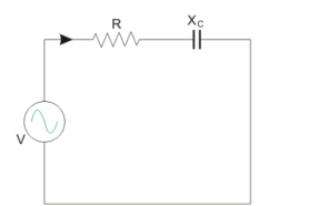
Y = 1/Z = Z -1 = 1/ R – j Xc
Xc = Capacitive reactance in Ω.
Y = 1/ R – j X L x ( R + j Xc / R + j Xc) = R + j Xc/ R2 + X C 2
Y = R / R 2 + Xc 2 + j X c / R 2 + Xc 2 = G + j Bc =  G2 + Bc 2
Bc = Capacitive susceptance in mho.
A sinewave is defined by the trigonometric sine function. The waveform repeats every 2p radians and is symmetrical about the voltage axis. The voltage and current exhibit cyclic behaviour referred as alternating current. The equation is represented as :
V(Ɵ) = Vpk . Sin(Ɵ) -----------------------(1)
There are several ways in which the amplitude of the sinewave is referenced say peak voltage, peak-to-peak voltage, average voltage, and root mean square voltage.
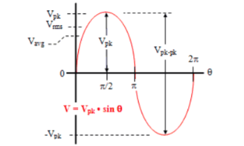
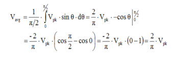
Average voltage:
Vavg is calculated by taking the average of the voltage in appropriate chosen interval. For the first quarter cycle that is 0 to π/2 radians.

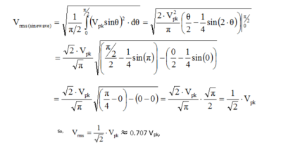
RMS voltage:
As the name implies, Vrms is calculated by taking the square root of the mean average of the square of the voltage in an appropriately chosen interval.
Form factor:
For a sinusoidal signal of peak voltage Vm it is given by :
Form factor of a sinusoidal signal = Vrms /Vav = 0.707 Vm / 0.637 Vm = 1.11
Peak Factor (Or Crest factor):
It is defined as the ratio of maximum value to the R.M.S value of an alternating quantity.
Peak factor of a sinusoidal signal=Vmax/Vrms =Vmax/(0.707 Vm) =1.414
Average Power:
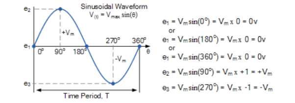
As the instantaneous power is the power at any instant of time, then:
p = v x i
Where v = Vm sin(wt+Ɵv)
i = Im sin(wt+Ɵi)
p = Vm sin(wt+Ɵv) Im sin(wt+Ɵi)
p= Vm Im [sin(wt+ Ɵv) sin(wt +Ɵi)]
p=Vm Im/2[cos Ɵ -cos(2wt+Ɵ)]
= Vm Im/2 = Vm/ x Im/
x Im/ =Vrms x Irms (W)
Where V and I are the root-mean-squared values of sinusoidal waveforms.
Complex power:
It is the product of the rms voltage phasor and the complex conjugate of the rms current phasor.
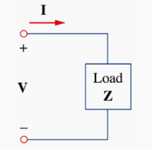
The voltage and current phasor
Given the phasor form V = Vm< Ɵv and I = Im<Ɵi of voltage v(t) and current i(t) the complex power S absorbed by the AC load is the product of the voltage and the complex conjugate of the current.
S = ½ V I * assuming the passive sign convention.
S = Vrms Irms *
Where Vrms = V/ = Vrms
  Ɵv and
Irms = I/ = Irms <Ɵi
S = Vrms Irms < Ɵv – Ɵi = Vrms Irms cos(Ɵv – Ɵi) +jVrms Irms sin(Ɵv – Ɵi).
The load impedance Z may be written as:
Z=V/I = Vrms/Irms = Vrms/Irms < Ɵv -Ɵi
Thus Vrms = Z x Irms
S = I 2 rms Z = V 2 rms / Z* = Vrms Irms *
Since I2 rms (R+jX) = P=jQ
Where P and Q are real and imaginary parts of the complex power that is
P = Re(S) = I2 rms R
Q = Im(S) = I2 rms X
Complex Power = S = P +jQ = Vrms (Irms) * = Vrms Irms < Ɵv - Ɵi
The three -phase system can be used as three single phase line so it can act as three single phase system.
The three- phase generation and single- phase generation is same in the generator except for the arrangement of coil in the generator to get a phase difference of 120o
Three voltage sources are connected to form a three- phase circuit present inside the generator. The generator is having three voltage sources which are acting together in 120o phase difference. If we can arrange three single-phase circuit with 120o phase difference, then it will become a three -phase circuit.
In three phase circuit, connections can be given in two types:
- Star connection
- Delta connection
Star Connection
In star connection, there is four wire, three wires are phase wire and fourth is neutral which is taken from the star point. Star connection is preferred for long distance power transmission because it is having the neutral point.
When equal current will flow through all the three phases, then it is called as balanced current. And when the current will not be equal in any of the phase, then it is unbalanced current.
In balanced condition there will be no current flowing through the neutral line and hence there is no use of the neutral terminal. But when there will be unbalanced current flowing in the three- phase circuit, neutral is having a vital role. It will take the unbalanced current through to the ground and protect the transformer. Unbalanced current affects transformer and cause damage to the transformer hence star connection is preferred for long distance transmission.
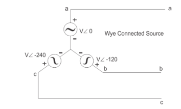
In star connection, the line voltage is √3 times of phase voltage. Line voltage is the voltage between two phases in three phase circuit and phase voltage is the voltage between one phase to the neutral line. And the current is same for both line and phase.
E line =  Ephase and I line = I phase
Delta Connection
In delta connection, there is three wires alone and no neutral terminal is taken. Normally delta connection is preferred for short distance due to the problem of unbalanced current in the circuit. The figure is shown below for delta connection. In the load station, ground can be used as neutral path if required.
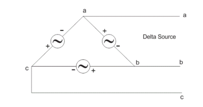
In delta connection, the line voltage is the same as that of phase voltage. And the line current is √3 times of phase current. It is shown as expression below,
E line = E phase and I line =  3 I Phase
An electric circuit is said to be a coupled circuit when there exists a mutual inductance between the coils or inductors present in the circuit. Coil is nothing but the series combination of resistor and inductor. In the absence of resistor, coil becomes inductor.
Mutual Inductance
If the flux produced by one coil links with the other coil, placed sufficiently close to the first coil, then due to the change in the flux produced by first coil, there is induced e.m.f. In second coil. Such induced e.m.f. In the second coil is called mutually induced e.m.f.
Let coil1 has N1 turns, while coil 2 has N2 turns. The current flowing through coil 1 is i1. Due to this current, the flux produced in coil 1 is Φ1. The part of this flux links with coil 2. This flux is called mutual flux.
It is denoted by Φ21 a sit is a part of flux Φ1 linking with coil 2. When current through coil 1 changes, the flux produced in coil 1 i.e. Φ1 changes. Thus, flux associated with coil 2 i.e. Φ21 changes. So according to the Faraday’s law, there will be induced e.m.f. In coil 2.
According to Faraday’s law, the magnitude of the induced e.m.f. Is given by,
V2 = N2 (dΦ21/dt) ……………..(1)
Now, Φ21 = Φ21/i x i
If the permeability of the surroundings is assumed constant, then Φ21 α i1 and hence Φ21/i is constant.
... Rate of change of Φ21 = Φ21/i x Rate of change of i1
... dΦ21/dt = Φ21/i1 x di1/dt ……………(2)
Putting value of dΦ21/dt in equation (1), the magnitude of the induced e.m.f. Can be written by as,
V2 = N2 (Φ21/i1 . di1/dt)
... V2 = (N2 Φ21/i1) di1/dt ……………(3)
Here the constant term (N2 Φ21/i1)is defined as coefficient of mutual inductance and it is denoted by M.
... M = N2 Φ21/ i1 ……………(4)
Then equation (3) can be written as,
... V2 = M di1/dt ………….(5)
Thus equation (5) indicates the magnitude of the e.m.f. Induced in coil 2 as a function of change in current in coil 1.
Dot convention is a technique, which gives the details about voltage polarity at the dotted terminal. While writing KVL equations.
- If the current enters at the dotted terminal of one coil or inductor, then it induces a voltage at another coil or inductor, which is having positive polarity at the dotted terminal.
- If the current leaves from the dotted terminal of one coil or inductor, then it induces a voltage at another coil or inductor, which is having negative polarity at the dotted terminal.
Classification of Coupling
We can classify coupling into the following two categories.
- Electrical Coupling
- Magnetic Coupling
Electrical Coupling
Electrical coupling occurs, when there exists a physical connection between two coils or inductors. This coupling can be of either aiding type or opposing type. It is based on whether the current enters at the dotted terminal or leaves from the dotted terminal.
Coupling of Aiding type
Consider the following electric circuit, which is having two inductors that are connected in series.
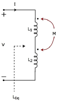
Since the two inductors are connected in series, the same current I flow through both inductors having self-inductances L1 and L2.
In this case, the current, I enter at the dotted terminal of each inductor. Hence, the induced voltage in each inductor will be having positive polarity at the dotted terminal due to the current flowing in another coil.
Apply KVL around the loop of the above electric circuit or network.
V – L1 dI/dt – M dI/dt – L2 dI/dt – M dI/dt =0
V = L1 dI/dt + L2 dI/dt + 2M dI/dt
V = (L1+L2+2M) dI/dt
The above equation is of the form:
V = L eq dI/dt
Therefore, the equivalent inductance of series combination of inductors
L eq = L1+L2+2M
Coupling of Opposing type
Consider the following electric circuit, which is having two inductors that are connected in series.
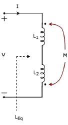
The current I enter at the dotted terminal of the inductor having an inductance of L1. Hence, it induces a voltage in the other inductor having an inductance of L2. So, positive polarity of the induced voltage is present at the dotted terminal of this inductor.
In the above circuit, the current I leaves from the dotted terminal of the inductor having an inductance of L2. Hence, it induces a voltage in the other inductor having an inductance of L1. So, negative polarity of the induced voltage is present at the dotted terminal of this inductor.
Apply KVL around the loop of the above electric circuit or network.
V = L1 dI/dt + L2 dI/dt - 2M dI/dt
V = (L1+L2-2M) dI/dt
V = Leq dI/dt
Leq = L1 + L2 -M
Magnetic Coupling
Magnetic coupling occurs, when there is no physical connection between two coils (or inductors). This coupling can be of either aiding type or opposing type. It is based on whether the current enters at the dotted terminal or leaves from the dotted terminal.
Coupling of Aiding type
Consider the following electrical equivalent circuit of transformer. It is having two coils, and these are called as primary and secondary coils.
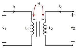
Apply KVL around primary coil
v 1 – L1 di/dt -M di2/dt =0
v1 = L1 di/dt + M di2/dt
Apply KVL around secondary coil
v 2 – L2 di2/dt – M di1/dt =0
v2 = L2 di2/dt + M di1/dt
In Equation 1 and Equation 2, the self-induced voltage and mutually induced voltage have the same polarity. Hence, the above transformer circuit is an example of magnetic coupling, which is of aiding type.
Coupling of Opposing Type
Consider the following electrical equivalent circuit of transformer.
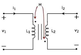
Apply KVL around primary coil
v 1 – L1 di1/dt – M di2/dt =0
v1 = L1 di1/dt + M di2/dt ----------------------------(1)
Apply KVL around the secondary coil
v 2 – L2 di2/dt – M di2/dt
v2 = L2 di2/dt + M di2/dt ----------------------------(2)
In Equation 3 and Equation 4, self-induced voltage and mutually induced voltage are having opposite polarity. Hence, the above transformer circuit is an example of magnetic coupling, which is of opposing type.
Example:
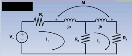
Solution:
KVL I1:
(R1 + R2 + ja)I1 – M I2 = Vs -----------------(1)
KVL I2:
-R2I1 + (R2+R3 +jb) I2 – M I1 =0 ………………………(2)

KVL I1 :
(R1 + ja +jb)I1 -jbI2 + M(I1-I2) + MI1 = Vs -----------(1)
KVL I2:
-jbI1 + (R2+jb-jc) I2 – M I1 =0 -----------------------------(2)
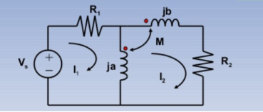
KVL I1 : (R1 +ja) I1 -jaI2 +MI2 = Vs -------------------(1)
KVL I2 : -jaI1 +(R2 + ja+jb) I2 – MI2 _ M(I2-I1) =0 ----------(2)
Ideal transformer can be defined as the transformer which id free of all types of losses. It is an imaginary transformer that has no core loss, no ohmic resistance and no leakage flux. It has the following characteristic:
- The resistance of their primary and secondary winding becomes zero.
- The core of the ideal transformer has infinite permeability.
- The leakage flux of the transformer becomes zero that is the whole of the flux induces into the core of the transformer links with their primary and secondary winding.
- The ideal transformer has 100% efficiency, the transformer is free from hysteresis and eddy current loss.
- In an ideal transformer there is no power loss. Therefore, output power is equal to input power.
E2 I2 cos ɸ = E1 I1 cos ɸ
E2 I2 = E1 I1
E2 / E1 = I1/I2
The transformation ratio is given by
V2/V1 = E2/E1 = N2/N1 = I1/I2 =K
Behaviour of Ideal Transformer:
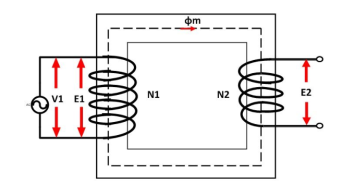
The voltage source V1 is applied across the primary winding of the transformer. The secondary winding is kept open. The N1 and N2 are the numbers of turns of their primary and secondary winding.
The current Im is the magnetizing current flows through the primary winding of the transformer. The magnetizing current produces the flux φm in the core of the transformer.
The flux link with the primary winding induces the emf E1 because of self-induction. The direction of the induced emf is inversely proportional to the applied voltage V1. The emf E2 induces in the secondary winding of the transformer because of mutual induction.
Phasor diagram of ideal transformer:
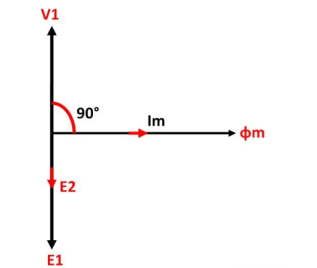
The phasor diagram of the ideal transformer is shown in the figure. As the coil of the primary transformer is purely inductive the magnetizing current induces in the transformer lag 90º by the input voltage V1.
The E1 and E2 are the emf induced in the primary and secondary winding of the transformer. The direction of the induced emf inversely proportional to the applied voltage.
References:
- Network theory by A.V Bakshi, U.A Bakshi
- Network Theory Analysis and Synthesis by Smarajit Ghosh
- Networks: An introduction by Mark Newman
- Network Theory (Bput) book by Satpathy