Unit 5
Magnetic Forces, Materials and Inductance
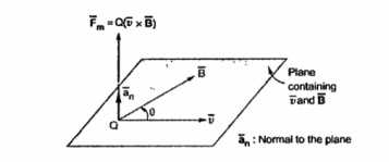
Consider a charge that is placed in a steady magnetic field. It experiences a force only if it is moving. Then the magnetic force ( ) exerted on a charge Q moving with velocity
  in a steady magnetic field
  is given by
 Q
Q  x
x 
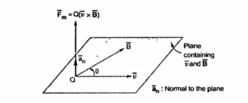
The magnitude of the magnetic force  is directly proportional to the magnitudes of Q v and B and also the sine of the angle between
  and
and  . The direction of
  is perpendicular to the plane containing
  and
and  both as shown in figure.
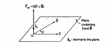
The magnitude force  is dependent on the velocity of the moving charge. But
  cannot perform work on a moving charge as it is right angle to the direction
Of motion of charge  . d
. d  =0 .
=0 .
The total force on a moving charge in the presence of both electric and magnetic fields is given by
F =  +
+  = Q(
= Q(  +
+  x
x  ) N
) N
The above equation is called Lorentz force equation which relates mechanical force to the electrical force. If the mass of the charge is m then
 = m
= m  = m. Dv/dt = Q(
  +
+  x
x  ) N
) N
A point charge of Q = -1.2 C has velocity  = ( 5
= ( 5  + 2
+ 2  - 3
- 3  ) m/s. Find the magnitude of the force exerted on the charge if
a) E = -18  + 5
+ 5  - 10
- 10  V/m
V/m
b)  = - 4
= - 4  + 4
+ 4  + 3
+ 3  T
T
The electric force exerted by  on charge Q is given by
 = Q .
= Q . 
= 1.2 [ -18  + 5
+ 5  - 10
- 10  ]
]
= 21.6  -6
-6  +12
+12  ]
]
Thus the magnitude of the electric force is given by
| = Q
= Q
The magnitude force exerted by  on charge Q is given by
 =
=  x
x 
= -1.2[ ( 5  + 2
+ 2  - 3
- 3  x ( - 4
  + 4
+ 4  + 3
+ 3  ) ]
) ]
= ( - 6  - 2.4
- 2.4  + 3.6
+ 3.6  ) x ( - 4
  + 4
+ 4  + 3
+ 3  )
)

[ - 7.2 – 14.4 ]  - [ -18 + 14.4]
  + [ -24 -9.6]
(-21.6  + 3.6
+ 3.6  -33.6
-33.6  ) N
) N
The magnitude of the magnetic force is given by
| =
=  (-21.6) 2 + (3.6 ) 2 +(33.6 ) 2 = 40.1058 N
The force exerted on a differential element of charge dQ moving in a steady magnetic field is given by
d = dQ
= dQ  x
x  N --------------------------(1)
The current density  can be expressed in terms of velocity of a volume charge density as ,
 =
=  .
.  -----------------------------------(2)
But the differential element of charge can be expressed in terms of the volume charge density as ,
DQ =  . Dv --------------------------------------------------(3)
Substituting value of dQ in
d  = =
= =  . d
. d  .
. 
Expressing d  in terms of
  we get
d  =
=  x
x  x dv
x dv
The relationship between current element is
 x dv =
  x ds = I x d
The force exerted on the current density on surface current density is given by
DF = (I dL x B)
Integrating equation over a volume the force is given by
 =
=  dv
dv
Integrating the equation we get
 =
=  x
x  dS
dS
Similarly integrating equation over a closed path we get
 =
=  d
d x
x 
If a conductor is straight and the field  is uniform along it then integrating equation we get the simple expression for the force as
 = I
= I x
x 
The magnitude of the force is given by
F = I L B sin Ɵ
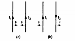
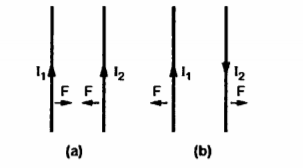
Consider two current carrying conductors placed parallel to each other. Each of this conductors produce its own flux around it. So, when such two conductors are placed close to each other there exists a force due to the interaction of two fluxes. The force between such parallel current carrying conductors depends on the directions of the two currents.
If the directions of both the currents are same, then the conductors experience a force of attraction. If the direction of two currents are opposite to each other then the conductors experience force of repulsion.
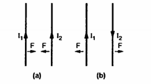
Let us consider two current elements I1  and I2
  as shown in the figure. As the currents are flowing in the same direction through the elements the force d(
 1) exerted on element I1
 due to magnetic field
  produced by other element I2
  is the force of attraction.
From the equation of force the force exerted on a differential current element is given by
d(d  ) = I1
  x d
x d
According to Bio-Savart’s law the magnetic field produced by the current element I2  is given by free space
x d =
=  d
d  =
=  [ I2
[ I2  x
x  R21 / 4
  R 2 21
Substituting the value of d
d ( d  =
=  x I1
x I1  x ( I2
  x
x  R21 ) / 4
  R 2 21
The equation represents force between two current elements .


The above equation indicates that the forces F1 and F2 obey Newton’s third law that for every action there is equal and opposite reaction.
For the two current carrying conductors of length l each the force exerted is given by
Ng in a net magnetic moment of an atom are
F =  I1 I2 l / 2 π d
The magnetic materials in which the orbital and spin magnetic moments do not cancel each other resulting in a net magnetic moment of an atom are called paramagnetic materials.
In paramagnetic materials atoms are oriented randomly. In absence of an external field the paramagnetic materials do not show any magnetic effect. But when an external is applied each atomic dipole moment experiences torque. Due to this all the atomic dipole moments tend to align with external field.
Thus insisde material value of the field increases than the value of external field if perfect alignment of dipole moments is achieved.
When the pramagnetic material is kept near the pole of strong magnets it gets attracted. The examples are potassium, tungsten, oxygen.
The materials in which the atoms have large dipole moment due to spin magnetic moments are called ferromagnetic materials. In ferromagnetic materials the adjacent atoms line up their magnetic dipole moments in parallel fashion. The region in which large number of magnetic moments lined in parallele are called domains.
When external field is applied the domains increase their size increasing internal field to high value. When the external field is removed the original random alignment of dipole moments is not aheived.
Some of the moments remain in a small region which results in residual field. This effect is called hysteresis.
The magnetization is defined as the magnetic dipole moment per unit volume. Its unit is A/m.
 = lim
= lim  ->0 1/

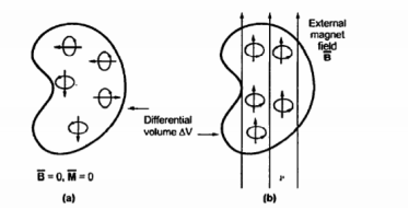
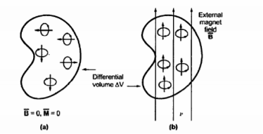
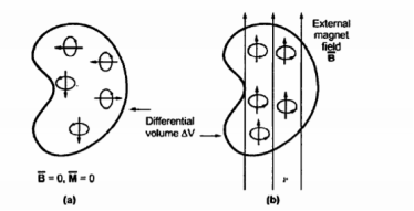
Consider a differential volume  . When an external field is not applied to the material there is a random orientation of the magnetic dipole moment as shown in fig (a). Thus the total sum of the magnetic dipole moments is zero. Thus the magnetization
  is also zero.
With the application of external field  the magnetic moment of electrons tend to align with
  on their own suh that the net magnetic moment is not equal to zero as shown in fig(b).
Let us consider the alignment of magnetic dipole along the closed path as shown in figure.
I =  / μo -
  ) . d
) . d 
Compare this equation with the expression of Ampere’s circuital law given by ,
I =  . d
. d 
We can write the relationship between  ,
,  and
and  as,
as,
 =
=  / μo -
 = μo(
= μo(  +
+  )
)
The relationship is true for all the materials irrespective of the nature of material whether it is linear or not.
For linear isotropic materials
 = xm
= xm 
Xm is dimensionless and called as magnetic suspectibility of the medium. Thus the magnetic suspectibility measures how suspectible the material is to a magnetic field.
Substituting value of  we get
 = μ
= μ  = μo μr
The relative permeability can be expressed in terms of magnetic suspectibility as
μr=(1+xm)= μ/μo
In general μ = μoμr is called the pemeability of the material.
In a certain region the magnetic flux density in a magnetic material is xm =6 given as  = 0.005 y 2
  T. At y=0.4m find the magnitude of
a)  b)
b)  c)
c) 
 =
=  x
x 
 =
=  / μ =
/ μ =  / μo μr =
  / μo(xm +1)
Putting the value of  we get
 =
=  x
x  / μo(xm + 1) = 1/ μo(xm + 1) (
  x
x 

= [0-0]  - [0 – ∂ /
  (0.005 y 2]
  + [ 0 - ∂/∂y(0.005 y 2)
= -(0.01y) 
 = 1/ μo(xm +1) [ -0.01 y
 = [ -0.01 y
 -0.01 y / 4 x π x 10 -7 (6+1).
Calculating the value of  at y=0.4
 -454.7284 A/m2
The conditions of the magnetic field existing at the boundary of the two media when the magnetic field passes from one medium to other are called boundary conditions for magnetic fields or simply magnetic boundary conditions.
When we consider magnetic boundary conditions the conditions  and
and  are studied at the boundary. The boundary between the two different magnetic materials is considered. To study the conditions of
  and
and  both the vectors are resolved into two components:
- Tangential to the boundary
- Normal or perpendicular to the boundary
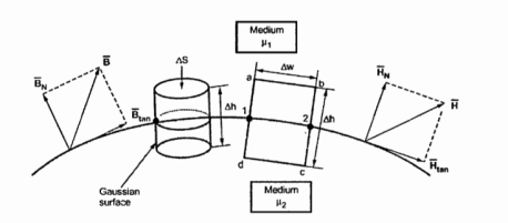
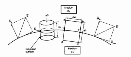
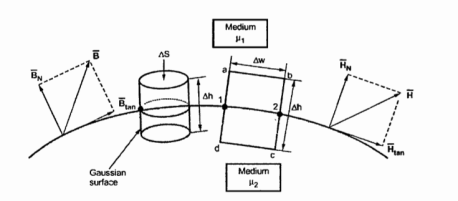
Consider a boundary between two isotropic homogeneous linear materials with different permeabilities μ1 and μ2 as shown in figure. To determine the boundary conditions use the closed path and the Gaussian surface.
According to the Gauss’s law for magnetic field
 . d
. d  = 0
= 0
The surface integral must be evaluated over three surfaces top , bottom and lateral.
Let the area of the top and bottom is same equal to ∆ S
 . d
. d  +
+  . d
. d  +
+  . d
. d  =0
=0
Let the magnitude of the normal component of  be B N1 and B N2 in medium 1 and medium 2 respectively. As both the surfaces are very small we can assume
B N1 and B N2 constant over their surfaces. Hence,
For top surface
 . d
. d  = B N1
  . d
. d  = B N1 ∆ S
For bottom surface
 . d
. d  = B N2
  . d
. d  = B N2 ∆ S
For lateral surface
 . d
. d  = 0.
= 0.
Putting the values of surface integrals we get
B N1 ∆ S - B N2 ∆ S = 0
The negative sign is used for one of the surface integrals because the normal component in medium 2 is entering the surface while in medium 1 the component is leaving the surface.
Hence,
B N1 ∆ S = B N2 ∆ S
B N1 = B N2
Thus, the normal component of  is continuous at the boundary. As the magnetic flux density and magnetic field intensity are related by
 = μ
= μ 
Thus, it can be written as
μ 1. HN1 = μ 2. HN2
HN1 / HN2 = μ2/μ1 = μ r2/ μ r1
For tangential :
According to Ampere’s circuital law,
 . d
. d  = I
= I
Consider a rectangular closed path abcda as shown in figure. It is traced in clockwise direction as a-b-c-d-a. This closed path in a plane normal to the boundary surface. Hence,  . d
. d  is divided into 6 parts.
 . d
. d  =
=  +
+ 
 +
+ 
 = I
= I
K. Dw = H tan1 (∆w) + HN1 (∆h/2) + HN2 (∆h/2) – H tan2 (∆w) – HN2 ((∆h/2) – HN1 (∆h/2)
To get conditions at boundary ∆h ->0 . Thus,
k.dw = H tan1 (∆w) – H tan2 (∆w)
H tan1 – H tan2 = K
In vector form we can express the above relation as
 tan1 -
  tan2 =
  N12 x
N12 x 
Where  N12 is the unit vector in the direction normal at the boundary from medium 1 to medium 2 .
For  the tangential components canbe related with permeabilities of two media using equation
B tan1 / μ1 = B tan2 / μ2 = K
Consider a special case that the boundary is free of current. When k=0
 tan1 -
  tan2 =
  N12 x
N12 x 
Where  N12 is the unit vector in the direction normal at the boundary from medium 1 to medium 2 .
For  the tangential components can be related with permeabilities of two media using
B tan1 / μ1 = B tan2 / μ2 = 0
B tan1 / μ1 = B tan2 / μ2
B tan1 / B tan2 = μ1 / μ2 = μr1/ μr2
The tangential component of  is continuous while
  is discontinuous at the boundary with the condition that the boundary is current free.
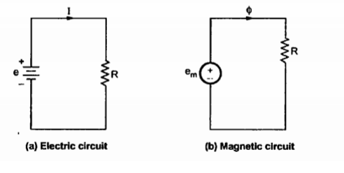
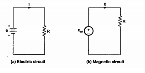
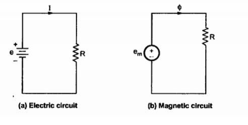
In magnetic circuits we determine the magnetic fluxes and magnetic field intensities in various parts of the circuits.
In case of magnetic circuits, we define the reluctance as

Where  = Permeability of the isotropic linear homogeneous material.
From electric circuit Ohm’s law is expressed as
 =
=  E
E
Consider the magnetic circuit. The magnetic flux density is analogous to current density therefore,
 = μ .
= μ . 
In the analysis of the magnetic circuits the equations are
∆ .  =0 and ∆ .
  =
= 
The two equations are expressed in terms of the total current flowing in magnetic circuit and the total magnetic flux density through cross-section of the magnetic circuit.
The total current in the magnetic circuit is given by
I =  . d
. d 
The total magnetic flux density flowing through the cross-section of the magnetic circuit is given by
ɸ =  . d
. d 
In magnetic circuit the reciprocal of reluctance is permeance. The permeance is measured in Henries .

When a coil with N turns carrying current I , the flux is produced by it. This flux links with each turn of the coil. Thus total flux linkage of the coil having N turns Nɸ Wb-turns .
The flux linked with the coil is proportional to the current I flowing through it. The ratio of total flux linkage to the current producing that flux is called inductance. It is measured in Henry.
Thus, inductance of a solenoid is given by
L = Total flux linkage / Total current
L = μ N 2 I A / l (I)
L = = μ N 2 A / l H
Calculate the inductance of a solenoid of 200 turns wound tightly on a cylindrical tube of 6cm diameter. The length of the tube is 60 cm and the solenoid is in air .
For a given solenoid in air ,
μ=μo = 4π x 10 -7
N = 200
d=6cm
l=6cm
The inductance of the solenoid is given by
L = μ N 2 A / l = μo N 2 (π r 2 ) / l
= 4 π x 10 -7 x (200) 2 x πx (3 x 10 -2 ) 2 / 60 x 10 -2
= 2.3687 x 10 -4 H
= 0.2368 m H
References:
- Faraday, Maxwell, and the Electromagnetic Field:by Basil Mahon and Nancy Forbes.
- ELECTROMAGNETISM: Theory and Applications Book by ASHUTOSH PRAMANIK
- Field and wave electromagnetics Textbook by David K. Cheng
References
- Faraday, Maxwell, and the Electromagnetic Field:by Basil Mahon and Nancy Forbes.
- ELECTROMAGNETISM: Theory and Applications Book by ASHUTOSH PRAMANIK
- Field and wave electromagnetics Textbook by David K. Cheng
Unit 5
Magnetic Forces, Materials and Inductance
Consider a charge that is placed in a steady magnetic field. It experiences a force only if it is moving. Then the magnetic force ( ) exerted on a charge Q moving with velocity
  in a steady magnetic field
  is given by
 Q
Q  x
x 
The magnitude of the magnetic force  is directly proportional to the magnitudes of Q v and B and also the sine of the angle between
  and
and  . The direction of
  is perpendicular to the plane containing
  and
and  both as shown in figure.
The magnitude force  is dependent on the velocity of the moving charge. But
  cannot perform work on a moving charge as it is right angle to the direction
Of motion of charge  . d
. d  =0 .
=0 .
The total force on a moving charge in the presence of both electric and magnetic fields is given by
F =  +
+  = Q(
= Q(  +
+  x
x  ) N
) N
The above equation is called Lorentz force equation which relates mechanical force to the electrical force. If the mass of the charge is m then
 = m
= m  = m. Dv/dt = Q(
  +
+  x
x  ) N
) N
A point charge of Q = -1.2 C has velocity  = ( 5
= ( 5  + 2
+ 2  - 3
- 3  ) m/s. Find the magnitude of the force exerted on the charge if
a) E = -18  + 5
+ 5  - 10
- 10  V/m
V/m
b)  = - 4
= - 4  + 4
+ 4  + 3
+ 3  T
T
The electric force exerted by  on charge Q is given by
 = Q .
= Q . 
= 1.2 [ -18  + 5
+ 5  - 10
- 10  ]
]
= 21.6  -6
-6  +12
+12  ]
]
Thus the magnitude of the electric force is given by
| = Q
= Q
The magnitude force exerted by  on charge Q is given by
 =
=  x
x 
= -1.2[ ( 5  + 2
+ 2  - 3
- 3  x ( - 4
  + 4
+ 4  + 3
+ 3  ) ]
) ]
= ( - 6  - 2.4
- 2.4  + 3.6
+ 3.6  ) x ( - 4
  + 4
+ 4  + 3
+ 3  )
)

[ - 7.2 – 14.4 ]  - [ -18 + 14.4]
  + [ -24 -9.6]
(-21.6  + 3.6
+ 3.6  -33.6
-33.6  ) N
) N
The magnitude of the magnetic force is given by
| =
=  (-21.6) 2 + (3.6 ) 2 +(33.6 ) 2 = 40.1058 N
The force exerted on a differential element of charge dQ moving in a steady magnetic field is given by
d = dQ
= dQ  x
x  N --------------------------(1)
The current density  can be expressed in terms of velocity of a volume charge density as ,
 =
=  .
.  -----------------------------------(2)
But the differential element of charge can be expressed in terms of the volume charge density as ,
DQ =  . Dv --------------------------------------------------(3)
Substituting value of dQ in
d  = =
= =  . d
. d  .
. 
Expressing d  in terms of
  we get
d  =
=  x
x  x dv
x dv
The relationship between current element is
 x dv =
  x ds = I x d
The force exerted on the current density on surface current density is given by
DF = (I dL x B)
Integrating equation over a volume the force is given by
 =
=  dv
dv
Integrating the equation we get
 =
=  x
x  dS
dS
Similarly integrating equation over a closed path we get
 =
=  d
d x
x 
If a conductor is straight and the field  is uniform along it then integrating equation we get the simple expression for the force as
 = I
= I x
x 
The magnitude of the force is given by
F = I L B sin Ɵ
Consider two current carrying conductors placed parallel to each other. Each of this conductors produce its own flux around it. So, when such two conductors are placed close to each other there exists a force due to the interaction of two fluxes. The force between such parallel current carrying conductors depends on the directions of the two currents.
If the directions of both the currents are same, then the conductors experience a force of attraction. If the direction of two currents are opposite to each other then the conductors experience force of repulsion.
Let us consider two current elements I1  and I2
  as shown in the figure. As the currents are flowing in the same direction through the elements the force d(
 1) exerted on element I1
 due to magnetic field
  produced by other element I2
  is the force of attraction.
From the equation of force the force exerted on a differential current element is given by
d(d  ) = I1
  x d
x d
According to Bio-Savart’s law the magnetic field produced by the current element I2  is given by free space
x d =
=  d
d  =
=  [ I2
[ I2  x
x  R21 / 4
  R 2 21
Substituting the value of d
d ( d  =
=  x I1
x I1  x ( I2
  x
x  R21 ) / 4
  R 2 21
The equation represents force between two current elements .


The above equation indicates that the forces F1 and F2 obey Newton’s third law that for every action there is equal and opposite reaction.
For the two current carrying conductors of length l each the force exerted is given by
Ng in a net magnetic moment of an atom are
F =  I1 I2 l / 2 π d
The magnetic materials in which the orbital and spin magnetic moments do not cancel each other resulting in a net magnetic moment of an atom are called paramagnetic materials.
In paramagnetic materials atoms are oriented randomly. In absence of an external field the paramagnetic materials do not show any magnetic effect. But when an external is applied each atomic dipole moment experiences torque. Due to this all the atomic dipole moments tend to align with external field.
Thus insisde material value of the field increases than the value of external field if perfect alignment of dipole moments is achieved.
When the pramagnetic material is kept near the pole of strong magnets it gets attracted. The examples are potassium, tungsten, oxygen.
The materials in which the atoms have large dipole moment due to spin magnetic moments are called ferromagnetic materials. In ferromagnetic materials the adjacent atoms line up their magnetic dipole moments in parallel fashion. The region in which large number of magnetic moments lined in parallele are called domains.
When external field is applied the domains increase their size increasing internal field to high value. When the external field is removed the original random alignment of dipole moments is not aheived.
Some of the moments remain in a small region which results in residual field. This effect is called hysteresis.
The magnetization is defined as the magnetic dipole moment per unit volume. Its unit is A/m.
 = lim
= lim  ->0 1/

Consider a differential volume  . When an external field is not applied to the material there is a random orientation of the magnetic dipole moment as shown in fig (a). Thus the total sum of the magnetic dipole moments is zero. Thus the magnetization
  is also zero.
With the application of external field  the magnetic moment of electrons tend to align with
  on their own suh that the net magnetic moment is not equal to zero as shown in fig(b).
Let us consider the alignment of magnetic dipole along the closed path as shown in figure.
I =  / μo -
  ) . d
) . d 
Compare this equation with the expression of Ampere’s circuital law given by ,
I =  . d
. d 
We can write the relationship between  ,
,  and
and  as,
as,
 =
=  / μo -
 = μo(
= μo(  +
+  )
)
The relationship is true for all the materials irrespective of the nature of material whether it is linear or not.
For linear isotropic materials
 = xm
= xm 
Xm is dimensionless and called as magnetic suspectibility of the medium. Thus the magnetic suspectibility measures how suspectible the material is to a magnetic field.
Substituting value of  we get
 = μ
= μ  = μo μr
The relative permeability can be expressed in terms of magnetic suspectibility as
μr=(1+xm)= μ/μo
In general μ = μoμr is called the pemeability of the material.
In a certain region the magnetic flux density in a magnetic material is xm =6 given as  = 0.005 y 2
  T. At y=0.4m find the magnitude of
a)  b)
b)  c)
c) 
 =
=  x
x 
 =
=  / μ =
/ μ =  / μo μr =
  / μo(xm +1)
Putting the value of  we get
 =
=  x
x  / μo(xm + 1) = 1/ μo(xm + 1) (
  x
x 

= [0-0]  - [0 – ∂ /
  (0.005 y 2]
  + [ 0 - ∂/∂y(0.005 y 2)
= -(0.01y) 
 = 1/ μo(xm +1) [ -0.01 y
 = [ -0.01 y
 -0.01 y / 4 x π x 10 -7 (6+1).
Calculating the value of  at y=0.4
 -454.7284 A/m2
The conditions of the magnetic field existing at the boundary of the two media when the magnetic field passes from one medium to other are called boundary conditions for magnetic fields or simply magnetic boundary conditions.
When we consider magnetic boundary conditions the conditions  and
and  are studied at the boundary. The boundary between the two different magnetic materials is considered. To study the conditions of
  and
and  both the vectors are resolved into two components:
- Tangential to the boundary
- Normal or perpendicular to the boundary
Consider a boundary between two isotropic homogeneous linear materials with different permeabilities μ1 and μ2 as shown in figure. To determine the boundary conditions use the closed path and the Gaussian surface.
According to the Gauss’s law for magnetic field
 . d
. d  = 0
= 0
The surface integral must be evaluated over three surfaces top , bottom and lateral.
Let the area of the top and bottom is same equal to ∆ S
 . d
. d  +
+  . d
. d  +
+  . d
. d  =0
=0
Let the magnitude of the normal component of  be B N1 and B N2 in medium 1 and medium 2 respectively. As both the surfaces are very small we can assume
B N1 and B N2 constant over their surfaces. Hence,
For top surface
 . d
. d  = B N1
  . d
. d  = B N1 ∆ S
For bottom surface
 . d
. d  = B N2
  . d
. d  = B N2 ∆ S
For lateral surface
 . d
. d  = 0.
= 0.
Putting the values of surface integrals we get
B N1 ∆ S - B N2 ∆ S = 0
The negative sign is used for one of the surface integrals because the normal component in medium 2 is entering the surface while in medium 1 the component is leaving the surface.
Hence,
B N1 ∆ S = B N2 ∆ S
B N1 = B N2
Thus, the normal component of  is continuous at the boundary. As the magnetic flux density and magnetic field intensity are related by
 = μ
= μ 
Thus, it can be written as
μ 1. HN1 = μ 2. HN2
HN1 / HN2 = μ2/μ1 = μ r2/ μ r1
For tangential :
According to Ampere’s circuital law,
 . d
. d  = I
= I
Consider a rectangular closed path abcda as shown in figure. It is traced in clockwise direction as a-b-c-d-a. This closed path in a plane normal to the boundary surface. Hence,  . d
. d  is divided into 6 parts.
 . d
. d  =
=  +
+ 
 +
+ 
 = I
= I
K. Dw = H tan1 (∆w) + HN1 (∆h/2) + HN2 (∆h/2) – H tan2 (∆w) – HN2 ((∆h/2) – HN1 (∆h/2)
To get conditions at boundary ∆h ->0 . Thus,
k.dw = H tan1 (∆w) – H tan2 (∆w)
H tan1 – H tan2 = K
In vector form we can express the above relation as
 tan1 -
  tan2 =
  N12 x
N12 x 
Where  N12 is the unit vector in the direction normal at the boundary from medium 1 to medium 2 .
For  the tangential components canbe related with permeabilities of two media using equation
B tan1 / μ1 = B tan2 / μ2 = K
Consider a special case that the boundary is free of current. When k=0
 tan1 -
  tan2 =
  N12 x
N12 x 
Where  N12 is the unit vector in the direction normal at the boundary from medium 1 to medium 2 .
For  the tangential components can be related with permeabilities of two media using
B tan1 / μ1 = B tan2 / μ2 = 0
B tan1 / μ1 = B tan2 / μ2
B tan1 / B tan2 = μ1 / μ2 = μr1/ μr2
The tangential component of  is continuous while
  is discontinuous at the boundary with the condition that the boundary is current free.
In magnetic circuits we determine the magnetic fluxes and magnetic field intensities in various parts of the circuits.
In case of magnetic circuits, we define the reluctance as

Where  = Permeability of the isotropic linear homogeneous material.
From electric circuit Ohm’s law is expressed as
 =
=  E
E
Consider the magnetic circuit. The magnetic flux density is analogous to current density therefore,
 = μ .
= μ . 
In the analysis of the magnetic circuits the equations are
∆ .  =0 and ∆ .
  =
= 
The two equations are expressed in terms of the total current flowing in magnetic circuit and the total magnetic flux density through cross-section of the magnetic circuit.
The total current in the magnetic circuit is given by
I =  . d
. d 
The total magnetic flux density flowing through the cross-section of the magnetic circuit is given by
ɸ =  . d
. d 
In magnetic circuit the reciprocal of reluctance is permeance. The permeance is measured in Henries .

When a coil with N turns carrying current I , the flux is produced by it. This flux links with each turn of the coil. Thus total flux linkage of the coil having N turns Nɸ Wb-turns .
The flux linked with the coil is proportional to the current I flowing through it. The ratio of total flux linkage to the current producing that flux is called inductance. It is measured in Henry.
Thus, inductance of a solenoid is given by
L = Total flux linkage / Total current
L = μ N 2 I A / l (I)
L = = μ N 2 A / l H
Calculate the inductance of a solenoid of 200 turns wound tightly on a cylindrical tube of 6cm diameter. The length of the tube is 60 cm and the solenoid is in air .
For a given solenoid in air ,
μ=μo = 4π x 10 -7
N = 200
d=6cm
l=6cm
The inductance of the solenoid is given by
L = μ N 2 A / l = μo N 2 (π r 2 ) / l
= 4 π x 10 -7 x (200) 2 x πx (3 x 10 -2 ) 2 / 60 x 10 -2
= 2.3687 x 10 -4 H
= 0.2368 m H
References:
- Faraday, Maxwell, and the Electromagnetic Field:by Basil Mahon and Nancy Forbes.
- ELECTROMAGNETISM: Theory and Applications Book by ASHUTOSH PRAMANIK
- Field and wave electromagnetics Textbook by David K. Cheng
References
- Faraday, Maxwell, and the Electromagnetic Field:by Basil Mahon and Nancy Forbes.
- ELECTROMAGNETISM: Theory and Applications Book by ASHUTOSH PRAMANIK
- Field and wave electromagnetics Textbook by David K. Cheng
Unit 5
Magnetic Forces, Materials and Inductance
Consider a charge that is placed in a steady magnetic field. It experiences a force only if it is moving. Then the magnetic force ( ) exerted on a charge Q moving with velocity
  in a steady magnetic field
  is given by
 Q
Q  x
x 
The magnitude of the magnetic force  is directly proportional to the magnitudes of Q v and B and also the sine of the angle between
  and
and  . The direction of
  is perpendicular to the plane containing
  and
and  both as shown in figure.
The magnitude force  is dependent on the velocity of the moving charge. But
  cannot perform work on a moving charge as it is right angle to the direction
Of motion of charge  . d
. d  =0 .
=0 .
The total force on a moving charge in the presence of both electric and magnetic fields is given by
F =  +
+  = Q(
= Q(  +
+  x
x  ) N
) N
The above equation is called Lorentz force equation which relates mechanical force to the electrical force. If the mass of the charge is m then
 = m
= m  = m. Dv/dt = Q(
  +
+  x
x  ) N
) N
A point charge of Q = -1.2 C has velocity  = ( 5
= ( 5  + 2
+ 2  - 3
- 3  ) m/s. Find the magnitude of the force exerted on the charge if
a) E = -18  + 5
+ 5  - 10
- 10  V/m
V/m
b)  = - 4
= - 4  + 4
+ 4  + 3
+ 3  T
T
The electric force exerted by  on charge Q is given by
 = Q .
= Q . 
= 1.2 [ -18  + 5
+ 5  - 10
- 10  ]
]
= 21.6  -6
-6  +12
+12  ]
]
Thus the magnitude of the electric force is given by
| = Q
= Q
The magnitude force exerted by  on charge Q is given by
 =
=  x
x 
= -1.2[ ( 5  + 2
+ 2  - 3
- 3  x ( - 4
  + 4
+ 4  + 3
+ 3  ) ]
) ]
= ( - 6  - 2.4
- 2.4  + 3.6
+ 3.6  ) x ( - 4
  + 4
+ 4  + 3
+ 3  )
)

[ - 7.2 – 14.4 ]  - [ -18 + 14.4]
  + [ -24 -9.6]
(-21.6  + 3.6
+ 3.6  -33.6
-33.6  ) N
) N
The magnitude of the magnetic force is given by
| =
=  (-21.6) 2 + (3.6 ) 2 +(33.6 ) 2 = 40.1058 N
The force exerted on a differential element of charge dQ moving in a steady magnetic field is given by
d = dQ
= dQ  x
x  N --------------------------(1)
The current density  can be expressed in terms of velocity of a volume charge density as ,
 =
=  .
.  -----------------------------------(2)
But the differential element of charge can be expressed in terms of the volume charge density as ,
DQ =  . Dv --------------------------------------------------(3)
Substituting value of dQ in
d  = =
= =  . d
. d  .
. 
Expressing d  in terms of
  we get
d  =
=  x
x  x dv
x dv
The relationship between current element is
 x dv =
  x ds = I x d
The force exerted on the current density on surface current density is given by
DF = (I dL x B)
Integrating equation over a volume the force is given by
 =
=  dv
dv
Integrating the equation we get
 =
=  x
x  dS
dS
Similarly integrating equation over a closed path we get
 =
=  d
d x
x 
If a conductor is straight and the field  is uniform along it then integrating equation we get the simple expression for the force as
 = I
= I x
x 
The magnitude of the force is given by
F = I L B sin Ɵ
Consider two current carrying conductors placed parallel to each other. Each of this conductors produce its own flux around it. So, when such two conductors are placed close to each other there exists a force due to the interaction of two fluxes. The force between such parallel current carrying conductors depends on the directions of the two currents.
If the directions of both the currents are same, then the conductors experience a force of attraction. If the direction of two currents are opposite to each other then the conductors experience force of repulsion.
Let us consider two current elements I1  and I2
  as shown in the figure. As the currents are flowing in the same direction through the elements the force d(
 1) exerted on element I1
 due to magnetic field
  produced by other element I2
  is the force of attraction.
From the equation of force the force exerted on a differential current element is given by
d(d  ) = I1
  x d
x d
According to Bio-Savart’s law the magnetic field produced by the current element I2  is given by free space
x d =
=  d
d  =
=  [ I2
[ I2  x
x  R21 / 4
  R 2 21
Substituting the value of d
d ( d  =
=  x I1
x I1  x ( I2
  x
x  R21 ) / 4
  R 2 21
The equation represents force between two current elements .


The above equation indicates that the forces F1 and F2 obey Newton’s third law that for every action there is equal and opposite reaction.
For the two current carrying conductors of length l each the force exerted is given by
Ng in a net magnetic moment of an atom are
F =  I1 I2 l / 2 π d
The magnetic materials in which the orbital and spin magnetic moments do not cancel each other resulting in a net magnetic moment of an atom are called paramagnetic materials.
In paramagnetic materials atoms are oriented randomly. In absence of an external field the paramagnetic materials do not show any magnetic effect. But when an external is applied each atomic dipole moment experiences torque. Due to this all the atomic dipole moments tend to align with external field.
Thus insisde material value of the field increases than the value of external field if perfect alignment of dipole moments is achieved.
When the pramagnetic material is kept near the pole of strong magnets it gets attracted. The examples are potassium, tungsten, oxygen.
The materials in which the atoms have large dipole moment due to spin magnetic moments are called ferromagnetic materials. In ferromagnetic materials the adjacent atoms line up their magnetic dipole moments in parallel fashion. The region in which large number of magnetic moments lined in parallele are called domains.
When external field is applied the domains increase their size increasing internal field to high value. When the external field is removed the original random alignment of dipole moments is not aheived.
Some of the moments remain in a small region which results in residual field. This effect is called hysteresis.
The magnetization is defined as the magnetic dipole moment per unit volume. Its unit is A/m.
 = lim
= lim  ->0 1/

Consider a differential volume  . When an external field is not applied to the material there is a random orientation of the magnetic dipole moment as shown in fig (a). Thus the total sum of the magnetic dipole moments is zero. Thus the magnetization
  is also zero.
With the application of external field  the magnetic moment of electrons tend to align with
  on their own suh that the net magnetic moment is not equal to zero as shown in fig(b).
Let us consider the alignment of magnetic dipole along the closed path as shown in figure.
I =  / μo -
  ) . d
) . d 
Compare this equation with the expression of Ampere’s circuital law given by ,
I =  . d
. d 
We can write the relationship between  ,
,  and
and  as,
as,
 =
=  / μo -
 = μo(
= μo(  +
+  )
)
The relationship is true for all the materials irrespective of the nature of material whether it is linear or not.
For linear isotropic materials
 = xm
= xm 
Xm is dimensionless and called as magnetic suspectibility of the medium. Thus the magnetic suspectibility measures how suspectible the material is to a magnetic field.
Substituting value of  we get
 = μ
= μ  = μo μr
The relative permeability can be expressed in terms of magnetic suspectibility as
μr=(1+xm)= μ/μo
In general μ = μoμr is called the pemeability of the material.
In a certain region the magnetic flux density in a magnetic material is xm =6 given as  = 0.005 y 2
  T. At y=0.4m find the magnitude of
a)  b)
b)  c)
c) 
 =
=  x
x 
 =
=  / μ =
/ μ =  / μo μr =
  / μo(xm +1)
Putting the value of  we get
 =
=  x
x  / μo(xm + 1) = 1/ μo(xm + 1) (
  x
x 

= [0-0]  - [0 – ∂ /
  (0.005 y 2]
  + [ 0 - ∂/∂y(0.005 y 2)
= -(0.01y) 
 = 1/ μo(xm +1) [ -0.01 y
 = [ -0.01 y
 -0.01 y / 4 x π x 10 -7 (6+1).
Calculating the value of  at y=0.4
 -454.7284 A/m2
The conditions of the magnetic field existing at the boundary of the two media when the magnetic field passes from one medium to other are called boundary conditions for magnetic fields or simply magnetic boundary conditions.
When we consider magnetic boundary conditions the conditions  and
and  are studied at the boundary. The boundary between the two different magnetic materials is considered. To study the conditions of
  and
and  both the vectors are resolved into two components:
- Tangential to the boundary
- Normal or perpendicular to the boundary
Consider a boundary between two isotropic homogeneous linear materials with different permeabilities μ1 and μ2 as shown in figure. To determine the boundary conditions use the closed path and the Gaussian surface.
According to the Gauss’s law for magnetic field
 . d
. d  = 0
= 0
The surface integral must be evaluated over three surfaces top , bottom and lateral.
Let the area of the top and bottom is same equal to ∆ S
 . d
. d  +
+  . d
. d  +
+  . d
. d  =0
=0
Let the magnitude of the normal component of  be B N1 and B N2 in medium 1 and medium 2 respectively. As both the surfaces are very small we can assume
B N1 and B N2 constant over their surfaces. Hence,
For top surface
 . d
. d  = B N1
  . d
. d  = B N1 ∆ S
For bottom surface
 . d
. d  = B N2
  . d
. d  = B N2 ∆ S
For lateral surface
 . d
. d  = 0.
= 0.
Putting the values of surface integrals we get
B N1 ∆ S - B N2 ∆ S = 0
The negative sign is used for one of the surface integrals because the normal component in medium 2 is entering the surface while in medium 1 the component is leaving the surface.
Hence,
B N1 ∆ S = B N2 ∆ S
B N1 = B N2
Thus, the normal component of  is continuous at the boundary. As the magnetic flux density and magnetic field intensity are related by
 = μ
= μ 
Thus, it can be written as
μ 1. HN1 = μ 2. HN2
HN1 / HN2 = μ2/μ1 = μ r2/ μ r1
For tangential :
According to Ampere’s circuital law,
 . d
. d  = I
= I
Consider a rectangular closed path abcda as shown in figure. It is traced in clockwise direction as a-b-c-d-a. This closed path in a plane normal to the boundary surface. Hence,  . d
. d  is divided into 6 parts.
 . d
. d  =
=  +
+ 
 +
+ 
 = I
= I
K. Dw = H tan1 (∆w) + HN1 (∆h/2) + HN2 (∆h/2) – H tan2 (∆w) – HN2 ((∆h/2) – HN1 (∆h/2)
To get conditions at boundary ∆h ->0 . Thus,
k.dw = H tan1 (∆w) – H tan2 (∆w)
H tan1 – H tan2 = K
In vector form we can express the above relation as
 tan1 -
  tan2 =
  N12 x
N12 x 
Where  N12 is the unit vector in the direction normal at the boundary from medium 1 to medium 2 .
For  the tangential components canbe related with permeabilities of two media using equation
B tan1 / μ1 = B tan2 / μ2 = K
Consider a special case that the boundary is free of current. When k=0
 tan1 -
  tan2 =
  N12 x
N12 x 
Where  N12 is the unit vector in the direction normal at the boundary from medium 1 to medium 2 .
For  the tangential components can be related with permeabilities of two media using
B tan1 / μ1 = B tan2 / μ2 = 0
B tan1 / μ1 = B tan2 / μ2
B tan1 / B tan2 = μ1 / μ2 = μr1/ μr2
The tangential component of  is continuous while
  is discontinuous at the boundary with the condition that the boundary is current free.
In magnetic circuits we determine the magnetic fluxes and magnetic field intensities in various parts of the circuits.
In case of magnetic circuits, we define the reluctance as

Where  = Permeability of the isotropic linear homogeneous material.
From electric circuit Ohm’s law is expressed as
 =
=  E
E
Consider the magnetic circuit. The magnetic flux density is analogous to current density therefore,
 = μ .
= μ . 
In the analysis of the magnetic circuits the equations are
∆ .  =0 and ∆ .
  =
= 
The two equations are expressed in terms of the total current flowing in magnetic circuit and the total magnetic flux density through cross-section of the magnetic circuit.
The total current in the magnetic circuit is given by
I =  . d
. d 
The total magnetic flux density flowing through the cross-section of the magnetic circuit is given by
ɸ =  . d
. d 
In magnetic circuit the reciprocal of reluctance is permeance. The permeance is measured in Henries .

When a coil with N turns carrying current I , the flux is produced by it. This flux links with each turn of the coil. Thus total flux linkage of the coil having N turns Nɸ Wb-turns .
The flux linked with the coil is proportional to the current I flowing through it. The ratio of total flux linkage to the current producing that flux is called inductance. It is measured in Henry.
Thus, inductance of a solenoid is given by
L = Total flux linkage / Total current
L = μ N 2 I A / l (I)
L = = μ N 2 A / l H
Calculate the inductance of a solenoid of 200 turns wound tightly on a cylindrical tube of 6cm diameter. The length of the tube is 60 cm and the solenoid is in air .
For a given solenoid in air ,
μ=μo = 4π x 10 -7
N = 200
d=6cm
l=6cm
The inductance of the solenoid is given by
L = μ N 2 A / l = μo N 2 (π r 2 ) / l
= 4 π x 10 -7 x (200) 2 x πx (3 x 10 -2 ) 2 / 60 x 10 -2
= 2.3687 x 10 -4 H
= 0.2368 m H
References:
- Faraday, Maxwell, and the Electromagnetic Field:by Basil Mahon and Nancy Forbes.
- ELECTROMAGNETISM: Theory and Applications Book by ASHUTOSH PRAMANIK
- Field and wave electromagnetics Textbook by David K. Cheng
References
- Faraday, Maxwell, and the Electromagnetic Field:by Basil Mahon and Nancy Forbes.
- ELECTROMAGNETISM: Theory and Applications Book by ASHUTOSH PRAMANIK
- Field and wave electromagnetics Textbook by David K. Cheng