MODULE 3
KINEMATICS OF RIGID BODY
A rigid body is an ideal body that does not change its shape when subjected to external forces or couples. The distance between the particles in a rigid body remains same during the motion. Hence, a rigid body can be defined as the group or collection of number of particles at fixed distance from each other.
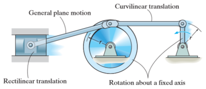
There are three types of motion of a rigid body
- Translation
- Rotation
- General Plane Motion
Kinematics of rigid body in translation motion
Translation motion occurs when a line (generally axis) in the body remains parallel to its initial orientation throughout the motion.
If the path of motion of any two lines on the rigid body is parallel or is in a straight line, then the translation is termed as rectilinear translation.
If the path of motion of any two lines on the rigid body is along the fixed curve, then the translation is termed as curvilinear translation.
Consider a rigid body that is subjected to translation motion as shown in fig.
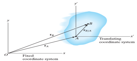
The position of points A and B is defined are defined by the position vectors  and
and  w.r.t the fixed frame x, y.
Let the translating system is fixed in a body with origin A which is referred to the base point. The position vector of B w.r.t A is denoted by  .
.
By vector addition, we get,


Taking, the first time derivative of the above equation, we get,

According to the definition of rigid body, the term  is constant
Hence,

And,  gives the absolute velocities
  and
and  respectively with respect to the fixed frame.
So, we get,

This shows that, for the rigid body in translation motion, the velocity of every particle on the body is same.
Now, taking the time derivative of the velocity equation, it simply yields

Where,  and
and  are the absolute accelerations of points A and B on the rigid body w.r.t fixed frame.
This shows that, for the rigid body in translation motion, the velocity and acceleration of every particle on the body is same.
Kinematics of a body rotating about fixed axis
When a rigid body is subjected to the rotation about a fixed axis, as shown in fig below, all the particles of the body, except those which lie on the axis of rotation, move along circular paths whose center lies on the axis of rotation.
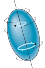
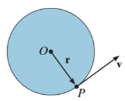
Consider, the point P on the rigid body defined by the position vector r. As the rigid body rotates about the fixed axis, then the point P travels a circular path of radius r with center point O as shown in fig below
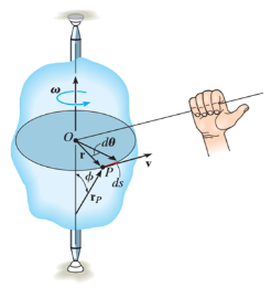
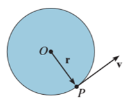
If the body rotates with a differential angular displacement  , then the point P displaces the distance
  , which is given by

Differentiating the above equation w.r.t time, we get

The term,  is referred to as the angular velocity
  of the rotating body
And  gives the velocity of point P
Hence,

The direction of velocity is tangent to the circular path.
Considering the magnitude and direction, velocity is the cross product of angular velocity and the position vector

Where,  is directed from axis to the point P
To find acceleration, differentiate velocity vector w.r.t time

Here, the term  refers to the angular acceleration
  of the rigid body
And  is the velocity
Hence,


Where,  is the tangential acceleration and
  is normal component of acceleration Hence,

Magnitude of both components is given by,


Tangential component refers to the time rate of change of velocity’s magnitude. Hence, if velocity of point P is increasing,  is in same direction of
  , but if velocity of point P is decreasing,
  is in direction opposite to that of
The normal component of acceleration refers to time rate of change of the velocity’s direction. Hence, the direction of the normal component is always from point P towards the center O. Hence it is also called as centripetal acceleration.

Rotation of a Body about a Fixed Axis
As a preliminary, let’s look at a body firmly attached to a rod fixed in space, and rotating with angular velocity Ω radians/sec. About that axis. You’ll recall from freshman physics that the angular momentum and rotational energy are

But you also know that both angular velocity and angular momentum are vectors. Obviously, for this example, the angular velocity is a vector pointing along the axis of rotation, Ω→= (0, 0,Ω z). One might be tempted to conclude that the angular momentum also points along the axis, but this is not always the case. An instructive example is provided by two masses m at the ends of a rod of length 2a held at a fixed angle θ to the z axis, which is the axis of rotation.
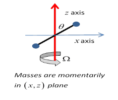
Lz =2ma2sin2θ⋅Ω.
But notice that, assuming the rod is momentarily in the xz plane, as shown, then
Lx=−2ma2cos2θ⋅Ω.
The total angular momentum is not parallel to the total angular velocity!
In fact, as should be evident, the total angular momentum is rotating around the constant angular velocity vector, so the axis must be providing a torque. This is why unbalanced car wheels stress the axle.
General Motion of a Rotating Rigid Body
We’ll follow the Landau notation (which itself tends to be bilingual between coordinates (x,y,z) and (x1,x2,x3).) Notice that we’ll label the components by (x1, x2, x3), not (r1, r2, r3) even though we call the vector r→. Again, we’re following Landau.
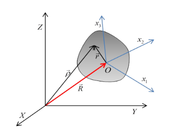
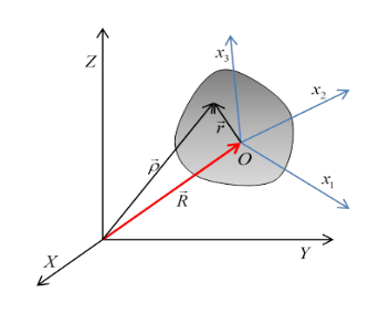
We take a fixed, inertial (or lab) coordinate system labelled (X,Y,Z) and in this system the rigid body’s center of mass, labelled O, is at R→. We have a Cartesian set of axes fixed in the body, origin at the center of mass, and coordinates in this system, vectors from O to a point in the body denoted by  , are labelled (x,y,z) or (x1,x2,x3).
A vector from the external inertial fixed origin to a point in the body is then

Suppose now that in infinitesimal time dt, the center of mass of the body moves  and the body rotates through
 . Then a particle at
  as measured from the center of mass will move through

Relative to the external inertial frame.
Therefore, the velocity of that particle in the fixed frame, writing the center of mass velocity and the angular velocity as

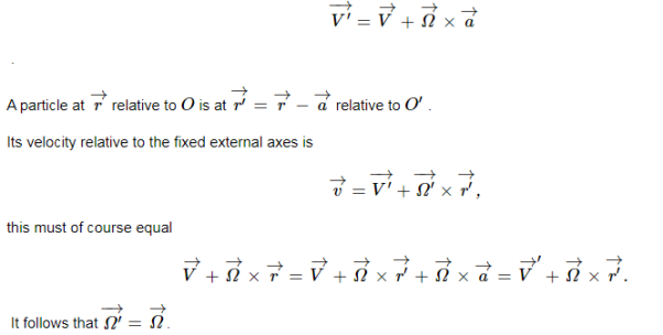
Now, in deriving the above equation, we have not used the fact that the origin O fixed in the body is at the center of mass. (That turns out to be useful shortly.) What if instead we had taken some other origin O′ fixed in the body? Would we find the angular velocity  about O′ to be the same as
  The answer turns out to be yes, but we need to prove it! Here's the proof:
If the position of O′ relative to O is  (a vector fixed in the body and so moving with it) then the velocity
  of O′ is
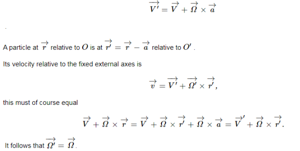
This means that if we describe the motion of any particle in the body in terms of some origin fixed in the body, plus rotation about that origin, the angular velocity vector describing the body’s motion is the same irrespective of the origin we choose. So we can, without ambiguity, talk about the angular velocity of the body.
Angular Velocity
The angular velocity of Fi0 with respect to Fi is

Note the ordering of the superscripts in this expression. Also, note that this vector
Quantity has the same components in either frame; that is,

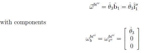
This simple expression results because it is a simple rotation. For the 2" rotation from Fi to Fi , the angular velocity vector is

Finally, for the 1" rotation from Fi00 to Fb, the angular velocity vector is
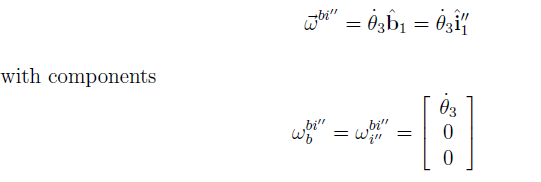
Thus, the angular velocities for simple rotations are also simple angular velocities. Now, angular velocity vectors add in the following way: the angular velocity of Fb with respect to Fi is equal to the sum of the angular velocity of Fb with respect to Fi , the angular velocity of Fi with respect to Fi , and the angular velocity of Fi with respect to Fi. Mathematically,

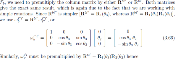
However, this expression involves vectors, which are mathematically abstract objects. In order to do computations involving angular velocities, we must choose a reference frame, and express all these vectors in that reference frame and add them together. In different reference frames. To add them, we must transform them all to the same frame. In most attitude dynamics applications, we use the body frame, so for this example, we develop the expression 
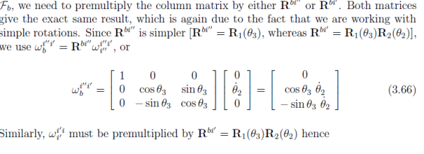

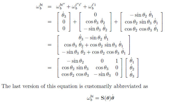
Now we have all the angular velocity vectors of Eq. (3.65) expressed in Fb and can add them together:
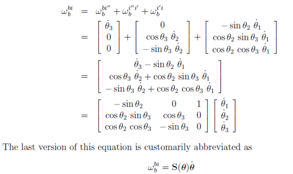
Where  = [
= [ 1
1  2
2  3]T , and S(
 ) obviously depends on which Euler angle sequence is used. For a given Euler angle sequence, it is relatively straightforward to develop the appropriate S(
 ). Often it is clear what angular velocity vector and reference frame we are working with, and we drop the sub and superscripts on !. Thus if the µ_'s are known, then they can be integrated to determine the µ's, and then the components of ~! can be determined. This integration is entirely analogous to knowing x_ , y_, and z_, and integrating these to determine the position x, y, and z. In this translational case however, one usually knows x_ , etc., from determining the velocity; i.e., v = [x_ y_ z_]T . The velocity is determined from the kinetics equations of motion as in Eq. (3.3). Similarly, for rotational motion, the kinetics equations of motion are used to determine the angular velocity, which is in turn used to determine the µ_'s, not vice versa. In the next section, we develop relationships between the time derivatives of the attitude variables and the angular velocity.
Rotation of a rigid body
An ordinary object does not simply rotate, it wobbles, shakes, and bends, so to simplify matters we shall discuss the motion of a non-existent ideal object which we call a rigid body. This means an object in which the forces between the atoms are so strong, and of such character, that the little forces that are needed to move it do not bend it. Its shape stays essentially the same as it moves about. If we wish to study the motion of such a body, and agree to ignore the motion of its center of mass, there is only one thing left for it to do, and that is to turn. We have to describe that. Suppose there is some line in the body which stays put (perhaps it includes the center of mass and perhaps not), and the body is rotating about this particular line as an axis. How do we define the rotation? That is easy enough, for if we mark a point somewhere on the object, anywhere except on the axis, we can always tell exactly where the object is, if we only know where this point has gone to. The only thing needed to describe the position of that point is an angle. So rotation consists of a study of the variations of the angle with time.
In order to study rotation, we observe the angle through which a body has turned. Of course, we are not referring to any particular angle inside the object itself; it is not that we draw some angle on the object. We are talking about the angular change of the position of the whole thing, from one time to another.
First, let us study the kinematics of rotations. The angle will change with time, and just as we talked about position and velocity in one dimension, we may talk about angular position and angular velocity in plane rotation. In fact, there is a very interesting relationship between rotation in two dimensions and one-dimensional displacement, in which almost every quantity has its analog. First, we have the angle θ which defines how far the body has gone around; this replaces the distance s, which defines how far it has gone along. In the same manner, we have a velocity of turning, ω=dθ/dt, which tells us how much the angle changes in a second, just as v=ds/dt describes how fast a thing moves, or how far it moves in a second. If the angle is measured in radians, then the angular velocity ω will be so and so many radians per second. The greater the angular velocity, the faster the object is turning, the faster the angle changes. We can go on: we can differentiate the angular velocity with respect to time, and we can call α= dω/dt= d2θ/dt2 the angular acceleration. That would be the analog of the ordinary acceleration.
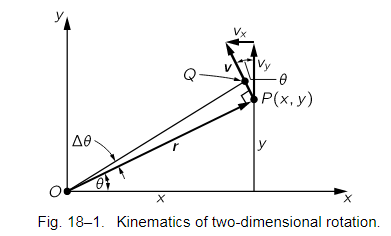
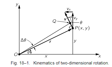
Now of course we shall have to relate the dynamics of rotation to the laws of dynamics of the particles of which the object is made, so we must find out how a particular particle moves when the angular velocity is such and such. To do this, let us take a certain particle which is located at a distance r from the axis and say it is in a certain location P(x,y) at a given instant, in the usual manner (Fig. 18–1). If at a moment Δt later the angle of the whole object has turned through Δθ, then this particle is carried with it. It is at the same radius away from O as it was before, but is carried to Q. The first thing we would like to know is how much the distance x changes and how much the distance y changes. If OP is called r, then the length PQ is rΔθ, because of the way angles are defined. The change in x, then, is simply the projection of rΔθ in the x-direction:
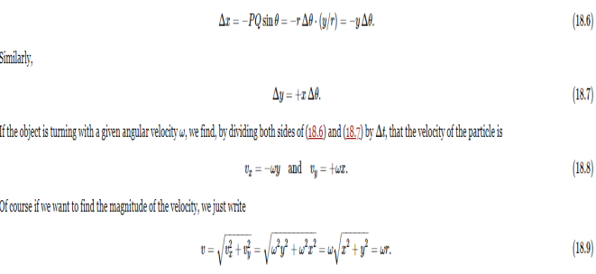
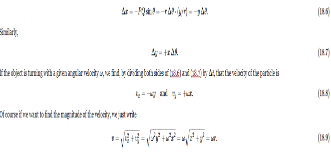
It should not be mysterious that the value of the magnitude of this velocity is ωr; in fact, it should be self-evident, because the distance that it moves is rΔθ and the distance it moves per second is r Δθ/Δt, or rω.
3 dimensional
Translation
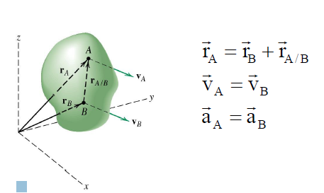
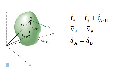
rA/B remains constant and therefore its time derivative is zero. Thus, all points in the body have the same velocity and the same acceleration.
Fixed axis theorem
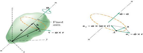
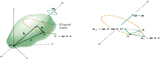
Any point such as A which is not on the axis moves in a circular arc in a plane normal to the axis and has a velocity and an acceleration

ROTATION ABOUT A FIXED POINT
When a body rotates about a fixed point, the angular velocity vector no longer remains fixed in direction, and this change calls for a more general concept of rotation.
Rotation and Proper Vectors
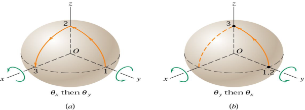
Consider a solid sphere which is cut from a rigid body confined to rotate about the fixed point P. The x-y-zaxis here are taken as fixed in space and do not rotate with the body.

In part (a) of the figure, two successive 90orotations of the sphere about, first, the x-axis and second, the y axis result in the motion of a point which is initially on the y-axis in position 1, to positions 2 and 3, successively.
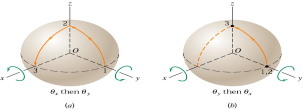
On the other hand, if the order of the rotations is reversed, the point undergoes no motion during the y-rotation but moves to point 3during the 90orotation about x-axis. Thus, the two cases do not produce the same final position, and it is evident from this one special example that finite rotations do not generally obey the parallelogram law of vector addition and are not commutative. (a+b≠b+a)
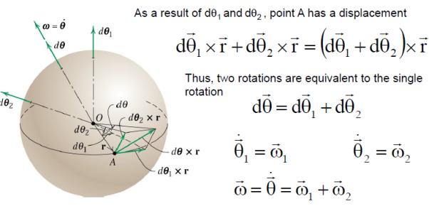
Thus, finite rotations may not be treated as proper vectors.
Infinitesimal rotations do obey the parallelogram law of vector addition. Infinitesimal rotations are d𝜃1 and d𝜃1
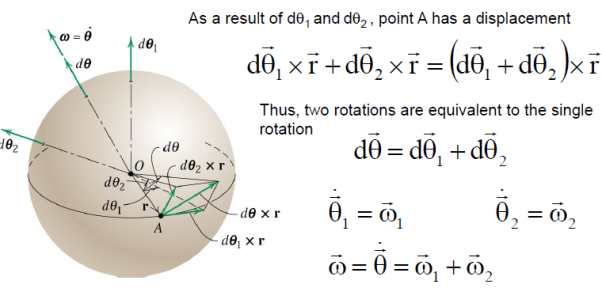
Suppose that γ:[0,1]→SO(3)γ:[0,1]→SO(3) is a path in the space of orientation preserving rotations of R3R3. It is classical that we can find a corresponding ω:[0,1]→R3ω:[0,1]→R3, the angular velocity, such that if r(t)=γ(t)r(0)r(t)=γ(t)r(0), then r′(t)=ω(t)×r(t)r′(t)=ω(t)×r(t) (where ×× is the cross product). Phrased differently, d/dt (γ(t))γ−1(t) is skew-symmetric with respect to an orthonormal basis. The correspondence between these two statements comes from the formula

It is worth pointing out that this formula underlies an isomorphism of Lie algebras (R3,×)≅so3(R3,×)≅so3, given by x↦adx
Assuming whatever niceness we need (likely just continuity), given ω(t)ω(t), there is a unique solution to the differential equation

In Dynamics it is often useful to describe motion relative to a coordinate frame that moves and that rotates—that is, not by referring to an inertial or Newtonian frame that is fixed to the Earth. This can happen if it’s needed to describe or analyse motion of components of a vehicle, that itself is moving in a fixed frame. Here we develop the so-called five-term acceleration equation in two dimensions, for the purpose of easier visualization. What is developed here can easily be extended to 3-D. This is one of the very nice results in Dynamics, because different types of acceleration come from this derivation, and the derivation itself simply involves repeated use of the product rule when differentiating vectors.
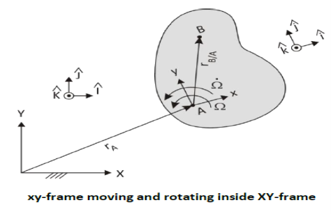
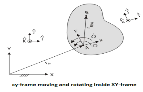
We start by describing the motion to be analysed, which involves every possibility of motion when there are two frames—one stationary and one moving and rotating—used to describe the motion. The figure shows the scenario
A conventional 2-D kinematic slab is shown. It is moving in a fixed reference frame, denoted with capital letters. On the slab is fixed a small-letter frame with A as its origin. This frame moves with the slab. Besides moving around in XY-space, the slab is also rotating at an angular speed Ω, which is also changing at a rate Ω̇. On the moving, rotating slab another point B has a motion of its own described in the little-letter coordinate system. Thus B moves relative to A, and this motion is described relative to the slab.
Position
We are interested in the motion of B in the XY-frame, since the absolute motion is what Newton’s Second Law applies to. We start with
𝑟⃗𝐵 = 𝑟⃗𝐴 + 𝑟⃗𝐵/𝐴
To see how 𝑟⃗𝐵 changes with time, it is useful to break it up into magnitudes and directions using unit vectors.
Thus 𝑟⃗𝐵 = 𝑟𝐴𝑋𝐼̂ + 𝑟𝐴𝑌𝐽̂ + 𝑟𝐵/𝐴−𝑥 𝑖̂ + 𝑟𝐵/𝐴−𝑦 𝑗 ̂
Since 𝑟⃗𝐵/𝐴 is a vector described in the little-letter coordinate system, it is more natural to express it in terms of 𝑖̂ and 𝑗̂ components.
Velocity
By definition 𝑣⃗𝐵 = 𝑟⃗̇𝐵
We use the product rule to differentiate 𝑟⃗ So
𝑣⃗𝐵 = 𝑟⃗̇𝐵= 𝑟̇𝐴𝑋𝐼̂ + 𝑟𝐴𝑋𝐼̂̇ + 𝑟̇𝐴𝑌𝐽̂ + 𝑟𝐴𝑌𝐽̂̇ + 𝑟̇𝐵 /𝐴 −𝑥 𝑖̂ + 𝑟𝐵 /𝐴 −𝑥𝑖̂̇+ 𝑟̇𝐵 /𝐴−𝑦 𝑗̂ + 𝑟𝐵 /𝐴 −𝑦 𝑗̂̇

All 𝑟̇ are changes in the magnitudes of the corresponding 𝑟 vectors, which are speed-ups or slow-downs. They are velocities, by definition. Thus
𝑣⃗𝐵 = 𝑣𝐴𝑋𝐼̂ + 𝑣𝐴𝑌𝐽̂ + 𝑣𝐵/𝐴 −𝑥 𝑖̂ + 𝑣𝐵 /𝐴−𝑦 𝑗̂ + 𝑟𝐵/𝐴−𝑥𝑖̂̇+ 𝑟𝐵/𝐴−𝑦 𝑗̂̇
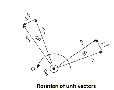
Now we need to find expressions for 𝑖̂̇ and 𝑗̂̇ Since they are unit vectors, they do not change length; they only change direction. They are fixed to the rotating slab AB so their changing depends solely on the slab rotation. The figure below shows this rotation in a magnified view.
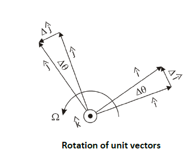
After a short ∆t, the slab has turned a small angle ∆𝜃 counter-clockwise. The change in the unit vector 𝑖̂ is shown as Δ𝑖̂ . The change in 𝑗̂ is shown as Δ𝑗̂. As Δt is made shorter and shorter, Δ𝑖̂ becomes perpendicular to 𝑖̂ , that is, rotated 90° counter-clockwise to 𝑖̂ , thus in the 𝑗̂-direction. Δ𝑗̂ is directed in the −𝑖̂-direction. In the limit, the magnitude of Δ𝑖̂ approaches the arc length. Since 𝑖̂ is a unit vector, the arc length is 1*∆𝜃 So Δ𝑖̂ = Δ𝜃 𝑗̂. From this, in the limit,
𝑖̂̇= Δ𝑖̂ / Δ𝑡 = Δ𝜃 / Δ𝑡 𝑗̂ = Ω 𝑗̂
And 𝑗̂̇= Δ𝑗̂ / Δ𝑡 = Δ𝜃 / Δ𝑡 (− 𝑖) = −Ω 𝑖̂
Now we can substitute these into the equation for 𝑣⃗ .
𝑣⃗𝐵 = 𝑣𝐴𝑋𝐼̂ + 𝑣𝐴𝑌𝐽̂ + 𝑣𝐵/𝐴−𝑥 𝑖̂ + 𝑣𝐵/𝐴−𝑦 𝑗̂ + 𝑟𝐵/𝐴−𝑥 Ω 𝑗̂ − 𝑟𝐵/𝐴−𝑦 Ω 𝑖̂
Reorganizing
𝑣⃗𝐵 = 𝑣𝐴𝑋𝐼̂ + 𝑣𝐴𝑌𝐽̂ + (𝑣𝐵/𝐴−𝑥 – 𝑟𝐵/𝐴−𝑦 Ω) 𝑖̂ + (𝑣𝐵/𝐴−𝑦 + 𝑟𝐵/𝐴−𝑥 Ω) 𝑗 ̂
On the right-hand side, after the first two terms, all of the terms have “B/A” in them. This indicates that the location and velocity of B is expressed in the little-letter coordinate system. Since we already have a lower-case x or y in the subscript, the “B/A” is somewhat redundant, and we shall dispense with it. Thus
𝑣⃗𝐵 = 𝑣𝐴𝑋 𝐼̂ + 𝑣𝐴𝑌 𝐽̂ + (𝑣𝑥 − 𝑟𝑦 Ω) 𝑖̂+ (𝑣𝑦 + 𝑟𝑥 Ω) 𝑗̂
Note that there are two velocities in the little-letter system. In the term 𝑣𝑥 − 𝑟𝑦 Ω, for example, 𝑣𝑥 is the rate of lengthening of the 𝑟⃗𝑥 vector, while 𝑟𝑥 Ω is a tangential velocity due purely to the rotation of the slab. Note that even if B were fixed to the plate, so that 𝑣𝑥 = 0 B still has a velocity due to the rotation of the plate and the location of B away from the xy-origin.
We can use this equation to reconstruct a vector version of 𝑣⃗𝐵 that does not include unit vectors.
𝑣⃗𝐵 = 𝑣⃗𝐴 + 𝑣⃗𝑥𝑦 + Ω⃗ × 𝑟⃗𝑥𝑦
Since Ω⃗ × 𝑟⃗𝑥𝑦 is due to Ω⃗, we can call this velocity 𝑣⃗Ω Then
𝑣⃗𝐵 = 𝑣⃗𝐴 + 𝑣⃗𝑥𝑦 + 𝑣⃗Ω
This is the three-term velocity equation. Recall that the subscript xy is a shorthand for B/A . If B is a fixed point on a component, then vxy = 0 . The term Ω⃗× 𝑟⃗𝑥𝑦 is thus 𝑣⃗𝐵/ . Thus the derived formula is the well-known relative velocity formulae
𝑣⃗𝐵 = 𝑣⃗𝐴 + 𝑣⃗𝐵/𝐴
𝑣⃗𝐵/𝐴 = 𝜔⃗𝐴𝐵 × 𝑟⃗𝐵/𝐴
We’ve seen so far how the three-term velocity equation results from vector differentiation. A physical picture of what is at play is shown in the figure below.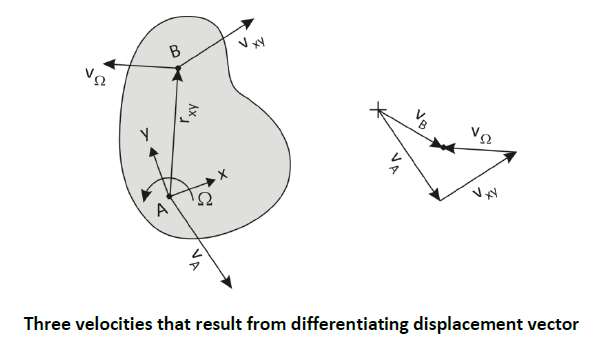
𝑣⃗𝐴 is just the translational movement of the xy-origin in the XY-frame. 𝑣⃗𝑥𝑦 is the translational motion of point B in the xy-frame, that is, on the slab. 𝑣⃗Ω is the motion of B due to the rotation of the slab.
Acceleration
By definition 𝑎⃗𝐵 = 𝑣⃗̇𝐵
We start with the three-term velocity equation in its detailed form above, so that we can see what accelerations result from what differentiations.
𝑣⃗𝐵 = 𝑣𝐴𝑋𝐼̂ + 𝑣𝐴𝑌𝐽̂ + (𝑣𝐵/𝐴−𝑥 – 𝑟𝐵/𝐴−𝑦 Ω) 𝑖̂ + (𝑣𝐵/𝐴−𝑦 + 𝑟𝐵/𝐴−𝑥 Ω) 𝑗 ̂
𝑣⃗̇𝐵 = 𝑣̇𝐴𝑋 𝐼̂ + 𝑣𝐴𝑋 𝐼̂̇+ 𝑣̇𝐴𝑌 𝐽̂+𝑣𝐴𝑌 𝐽̂̇+ (𝑣̇𝑥 − 𝑟̇𝑦 Ω − 𝑟𝑦 Ω̇) 𝑖̂+ (𝑣𝑥 − 𝑟𝑦 Ω) 𝑖̂̇+ (𝑣̇𝑦 + 𝑟̇𝑥 Ω + 𝑟𝑥 Ω̇) 𝑗̂ + (𝑣𝑦 + 𝑟𝑥 Ω) 𝑗̂
Again 𝐼̂ and 𝐽̂ belong to the fixed frame, so they don’t change and are 0. Also we can substitute in the results for 𝑖̂̇ and 𝑗̂̇ previously calculated. 𝑟̇ is 𝑣, and 𝑣̇ is .
𝑣⃗̇𝐵 = 𝑎𝐴𝑋 𝐼̂ + 𝑎𝐴𝑌 𝐽̂ + (𝑎𝑥 − 𝑣𝑦 Ω − 𝑟𝑦 Ω̇) 𝑖̂+ (𝑣𝑥 − 𝑟𝑦 Ω) Ω 𝑗̂+ (𝑎𝑦 + 𝑣𝑥 Ω + 𝑟𝑥 Ω̇) 𝑗̂ + (𝑣𝑦 + 𝑟𝑥 Ω)(−Ω 𝑖̂)
𝑎⃗𝐵 = 𝑎𝐴𝑋 𝐼̂ + 𝑎𝐴𝑌𝐽̂ + (𝑎𝑥 − 2𝑣𝑦 Ω − 𝑟𝑦 Ω̇− 𝑟𝑥 Ω2) 𝑖̂+ (𝑎𝑦 + 2𝑣𝑥 Ω + 𝑟𝑥 Ω̇− 𝑟𝑦 Ω2) 𝑗̂
This is the five-term acceleration equation.
The five accelerations, though they arose simply from applying the product rule to vector differentiation, can be ascribed definitive physical meaning. Let’s define them first with a shorthand notation and then discuss their characteristics.
1. 𝑎⃗𝐴 = 𝑎𝐴𝑋 𝐼̂ + 𝑎𝐴𝑌 𝐽̂, the acceleration of point A in the fixed XY-frame
2. 𝑎⃗𝑥𝑦 = 𝑎𝑥 𝑖̂+ 𝑎𝑦 𝑗̂, the acceleration of B within the moving, rotating xy-frame
3. 𝑎⃗𝐶 = −2𝑣𝑦 Ω 𝑖̂+ 2𝑣𝑥 Ω 𝑗̂, the Coriolis acceleration of B
4. 𝑎⃗𝑡 = −𝑟𝑦 Ω̇ 𝑖̂+ 𝑟𝑥 Ω̇ 𝑗̂, the tangential acceleration of B
5. 𝑎⃗𝑛 = −𝑟𝑥 Ω2 𝑖̂− 𝑟𝑦 Ω2 𝑗̂, the normal acceleration of B
So 𝑎⃗𝐵 = 𝑎⃗𝐴 + 𝑎⃗𝑥𝑦 + 𝑎⃗𝐶 + 𝑎⃗𝑡 + 𝑎⃗𝑛
𝑎⃗𝐴 And 𝑎⃗𝑥𝑦 are both independent accelerations and do not involve the rotation of the slab. Normally in an analysis they will have to be given or observed. The other three accelerations do involve the rotation of the slab. 𝑎⃗𝑡 involves a speed-up of the tangential velocity, 𝑣⃗Ω, simply because the spin speed is increasing…or a slow-down in 𝑣⃗Ω because the spin speed is decreasing. 𝑎⃗𝑛 is due to the constant change in direction of 𝑣⃗Ω as it seemingly rotates about A. Note that this is directed opposite to 𝑟⃗𝑥𝑦 which is 𝑟⃗𝐵/ . The third term, Coriolis acceleration, is the most puzzling and misunderstood of the five. It results from a combination of movements: movement on the slab while it is rotating. It was not even known until long after Newton developed his three laws and Euler extended them to rigid bodies.
The three accelerations involving Ω⃗ can also be cast as cross products.
3. 𝑎⃗𝐶 = 2 Ω⃗ × 𝑣⃗𝑥𝑦 the Coriolis acceleration of B
4. 𝑎⃗𝑡 = Ω⃗ ̇ × 𝑟⃗𝑥𝑦, the tangential acceleration of B
5. 𝑎⃗𝑛 = Ω⃗ × (Ω⃗ × 𝑟⃗𝑥𝑦), the normal acceleration of B
That these are equivalent to the unit-vector versions above can be seen as follows. The magnitude equivalency can be verified by inspection. The directions can be seen in that in 2-D, positive Ω⃗ and Ω⃗ point out of the slab. Pre-crossing them with a vector produces a vector that is rotated 90° to the right of the second vector in the cross-product. Also, since both Ω⃗ and Ω⃗ ̇ point in the 𝑘 ̂ direction (if they are positive), they will convert 𝑖̂-components into 𝑗̂-components and 𝑗̂-components into −𝑖̂-components. Note that 𝑎⃗𝐶 and 𝑎⃗𝑡 have y-components in the −𝑖̂-direction and x-components in the 𝑗̂-direction. With 𝑎⃗ , there is a double pre-crossing by Ω⃗ . Thus the direction is turned 180° around from 𝑟⃗𝑥𝑦.
In the second pre-cross, the x-components that had been turned into the 𝑗̂-direction get turned another 90° into the −𝑖̂-direction. Note that in the unit-vector version of 𝑎⃗𝑛 x-components stay as 𝑖̂-components, and y-components stay as 𝑗̂- components. But both are now negative
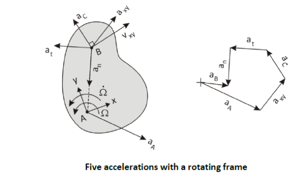
The figure above shows an example of the five accelerations. 𝑎⃗𝐴 and 𝑎⃗𝑥𝑦 are independent and could be drawn in any direction. The Coriolis acceleration is perpendicular and to the left of 𝑣⃗𝑥𝑦 since the slab is rotating counter-clockwise. 𝑎⃗𝑡 is perpendicular and to the left of the line from A to B since Ω⃗ ̇ is counter-clockwise. 𝑎⃗𝑛 leads from B back toward the apparent center of rotation at A .
Though this is explained in 2-D for visualization purposed, it is equally valid for 3-D.
Also noteworthy is that the center of rotation of the slab does not have to be at A . It does look to an observer at A as if the slab is rotating about him. But the rotation point does not even have to be fixed. It could change with time, like an instant center does, in the general case. It could even be, if we take the special case of B not moving on the slab, that B is the center of rotation. But all of the above is still true, and we can center our rotating coordinate system at any point on the slab. I would like to work out this counter-case at some point, just to demonstrate it.
MODULE 3
KINEMATICS OF RIGID BODY
A rigid body is an ideal body that does not change its shape when subjected to external forces or couples. The distance between the particles in a rigid body remains same during the motion. Hence, a rigid body can be defined as the group or collection of number of particles at fixed distance from each other.
There are three types of motion of a rigid body
- Translation
- Rotation
- General Plane Motion
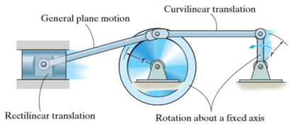
Kinematics of rigid body in translation motion
Translation motion occurs when a line (generally axis) in the body remains parallel to its initial orientation throughout the motion.
If the path of motion of any two lines on the rigid body is parallel or is in a straight line, then the translation is termed as rectilinear translation.
If the path of motion of any two lines on the rigid body is along the fixed curve, then the translation is termed as curvilinear translation.
Consider a rigid body that is subjected to translation motion as shown in fig.
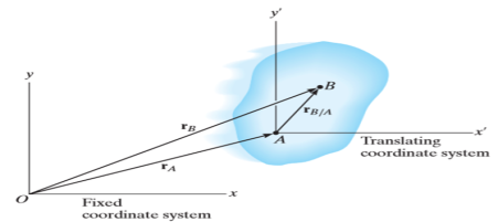
The position of points A and B is defined are defined by the position vectors  and
and  w.r.t the fixed frame x, y.
Let the translating system is fixed in a body with origin A which is referred to the base point. The position vector of B w.r.t A is denoted by  .
.
By vector addition, we get,


Taking, the first time derivative of the above equation, we get,

According to the definition of rigid body, the term  is constant
Hence,

And,  gives the absolute velocities
  and
and  respectively with respect to the fixed frame.
So, we get,

This shows that, for the rigid body in translation motion, the velocity of every particle on the body is same.
Now, taking the time derivative of the velocity equation, it simply yields

Where,  and
and  are the absolute accelerations of points A and B on the rigid body w.r.t fixed frame.
This shows that, for the rigid body in translation motion, the velocity and acceleration of every particle on the body is same.
Kinematics of a body rotating about fixed axis
When a rigid body is subjected to the rotation about a fixed axis, as shown in fig below, all the particles of the body, except those which lie on the axis of rotation, move along circular paths whose center lies on the axis of rotation.
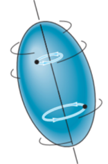
Consider, the point P on the rigid body defined by the position vector r. As the rigid body rotates about the fixed axis, then the point P travels a circular path of radius r with center point O as shown in fig below
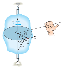
If the body rotates with a differential angular displacement  , then the point P displaces the distance
  , which is given by

Differentiating the above equation w.r.t time, we get

The term,  is referred to as the angular velocity
  of the rotating body
And  gives the velocity of point P
Hence,

The direction of velocity is tangent to the circular path.
Considering the magnitude and direction, velocity is the cross product of angular velocity and the position vector

Where,  is directed from axis to the point P
To find acceleration, differentiate velocity vector w.r.t time

Here, the term  refers to the angular acceleration
  of the rigid body
And  is the velocity
Hence,


Where,  is the tangential acceleration and
  is normal component of acceleration Hence,

Magnitude of both components is given by,


Tangential component refers to the time rate of change of velocity’s magnitude. Hence, if velocity of point P is increasing,  is in same direction of
  , but if velocity of point P is decreasing,
  is in direction opposite to that of
The normal component of acceleration refers to time rate of change of the velocity’s direction. Hence, the direction of the normal component is always from point P towards the center O. Hence it is also called as centripetal acceleration.

Rotation of a Body about a Fixed Axis
As a preliminary, let’s look at a body firmly attached to a rod fixed in space, and rotating with angular velocity Ω radians/sec. About that axis. You’ll recall from freshman physics that the angular momentum and rotational energy are

But you also know that both angular velocity and angular momentum are vectors. Obviously, for this example, the angular velocity is a vector pointing along the axis of rotation, Ω→= (0, 0,Ω z). One might be tempted to conclude that the angular momentum also points along the axis, but this is not always the case. An instructive example is provided by two masses m at the ends of a rod of length 2a held at a fixed angle θ to the z axis, which is the axis of rotation.
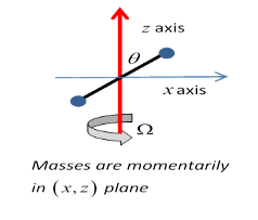
Lz =2ma2sin2θ⋅Ω.
But notice that, assuming the rod is momentarily in the xz plane, as shown, then
Lx=−2ma2cos2θ⋅Ω.
The total angular momentum is not parallel to the total angular velocity!
In fact, as should be evident, the total angular momentum is rotating around the constant angular velocity vector, so the axis must be providing a torque. This is why unbalanced car wheels stress the axle.
General Motion of a Rotating Rigid Body
We’ll follow the Landau notation (which itself tends to be bilingual between coordinates (x,y,z) and (x1,x2,x3).) Notice that we’ll label the components by (x1, x2, x3), not (r1, r2, r3) even though we call the vector r→. Again, we’re following Landau.
We take a fixed, inertial (or lab) coordinate system labelled (X,Y,Z) and in this system the rigid body’s center of mass, labelled O, is at R→. We have a Cartesian set of axes fixed in the body, origin at the center of mass, and coordinates in this system, vectors from O to a point in the body denoted by  , are labelled (x,y,z) or (x1,x2,x3).
A vector from the external inertial fixed origin to a point in the body is then

Suppose now that in infinitesimal time dt, the center of mass of the body moves  and the body rotates through
 . Then a particle at
  as measured from the center of mass will move through

Relative to the external inertial frame.
Therefore, the velocity of that particle in the fixed frame, writing the center of mass velocity and the angular velocity as

Now, in deriving the above equation, we have not used the fact that the origin O fixed in the body is at the center of mass. (That turns out to be useful shortly.) What if instead we had taken some other origin O′ fixed in the body? Would we find the angular velocity  about O′ to be the same as
  The answer turns out to be yes, but we need to prove it! Here's the proof:
If the position of O′ relative to O is  (a vector fixed in the body and so moving with it) then the velocity
  of O′ is
This means that if we describe the motion of any particle in the body in terms of some origin fixed in the body, plus rotation about that origin, the angular velocity vector describing the body’s motion is the same irrespective of the origin we choose. So we can, without ambiguity, talk about the angular velocity of the body.
Angular Velocity
The angular velocity of Fi0 with respect to Fi is

Note the ordering of the superscripts in this expression. Also, note that this vector
Quantity has the same components in either frame; that is,

This simple expression results because it is a simple rotation. For the 2" rotation from Fi to Fi , the angular velocity vector is

Finally, for the 1" rotation from Fi00 to Fb, the angular velocity vector is
Thus, the angular velocities for simple rotations are also simple angular velocities. Now, angular velocity vectors add in the following way: the angular velocity of Fb with respect to Fi is equal to the sum of the angular velocity of Fb with respect to Fi , the angular velocity of Fi with respect to Fi , and the angular velocity of Fi with respect to Fi. Mathematically,

However, this expression involves vectors, which are mathematically abstract objects. In order to do computations involving angular velocities, we must choose a reference frame, and express all these vectors in that reference frame and add them together. In different reference frames. To add them, we must transform them all to the same frame. In most attitude dynamics applications, we use the body frame, so for this example, we develop the expression 

Now we have all the angular velocity vectors of Eq. (3.65) expressed in Fb and can add them together:
Where  = [
= [ 1
1  2
2  3]T , and S(
 ) obviously depends on which Euler angle sequence is used. For a given Euler angle sequence, it is relatively straightforward to develop the appropriate S(
 ). Often it is clear what angular velocity vector and reference frame we are working with, and we drop the sub and superscripts on !. Thus if the µ_'s are known, then they can be integrated to determine the µ's, and then the components of ~! can be determined. This integration is entirely analogous to knowing x_ , y_, and z_, and integrating these to determine the position x, y, and z. In this translational case however, one usually knows x_ , etc., from determining the velocity; i.e., v = [x_ y_ z_]T . The velocity is determined from the kinetics equations of motion as in Eq. (3.3). Similarly, for rotational motion, the kinetics equations of motion are used to determine the angular velocity, which is in turn used to determine the µ_'s, not vice versa. In the next section, we develop relationships between the time derivatives of the attitude variables and the angular velocity.
Rotation of a rigid body
An ordinary object does not simply rotate, it wobbles, shakes, and bends, so to simplify matters we shall discuss the motion of a non-existent ideal object which we call a rigid body. This means an object in which the forces between the atoms are so strong, and of such character, that the little forces that are needed to move it do not bend it. Its shape stays essentially the same as it moves about. If we wish to study the motion of such a body, and agree to ignore the motion of its center of mass, there is only one thing left for it to do, and that is to turn. We have to describe that. Suppose there is some line in the body which stays put (perhaps it includes the center of mass and perhaps not), and the body is rotating about this particular line as an axis. How do we define the rotation? That is easy enough, for if we mark a point somewhere on the object, anywhere except on the axis, we can always tell exactly where the object is, if we only know where this point has gone to. The only thing needed to describe the position of that point is an angle. So rotation consists of a study of the variations of the angle with time.
In order to study rotation, we observe the angle through which a body has turned. Of course, we are not referring to any particular angle inside the object itself; it is not that we draw some angle on the object. We are talking about the angular change of the position of the whole thing, from one time to another.
First, let us study the kinematics of rotations. The angle will change with time, and just as we talked about position and velocity in one dimension, we may talk about angular position and angular velocity in plane rotation. In fact, there is a very interesting relationship between rotation in two dimensions and one-dimensional displacement, in which almost every quantity has its analog. First, we have the angle θ which defines how far the body has gone around; this replaces the distance s, which defines how far it has gone along. In the same manner, we have a velocity of turning, ω=dθ/dt, which tells us how much the angle changes in a second, just as v=ds/dt describes how fast a thing moves, or how far it moves in a second. If the angle is measured in radians, then the angular velocity ω will be so and so many radians per second. The greater the angular velocity, the faster the object is turning, the faster the angle changes. We can go on: we can differentiate the angular velocity with respect to time, and we can call α= dω/dt= d2θ/dt2 the angular acceleration. That would be the analog of the ordinary acceleration.
Now of course we shall have to relate the dynamics of rotation to the laws of dynamics of the particles of which the object is made, so we must find out how a particular particle moves when the angular velocity is such and such. To do this, let us take a certain particle which is located at a distance r from the axis and say it is in a certain location P(x,y) at a given instant, in the usual manner (Fig. 18–1). If at a moment Δt later the angle of the whole object has turned through Δθ, then this particle is carried with it. It is at the same radius away from O as it was before, but is carried to Q. The first thing we would like to know is how much the distance x changes and how much the distance y changes. If OP is called r, then the length PQ is rΔθ, because of the way angles are defined. The change in x, then, is simply the projection of rΔθ in the x-direction:
It should not be mysterious that the value of the magnitude of this velocity is ωr; in fact, it should be self-evident, because the distance that it moves is rΔθ and the distance it moves per second is r Δθ/Δt, or rω.
3 dimensional
Translation
rA/B remains constant and therefore its time derivative is zero. Thus, all points in the body have the same velocity and the same acceleration.
Fixed axis theorem
Any point such as A which is not on the axis moves in a circular arc in a plane normal to the axis and has a velocity and an acceleration

ROTATION ABOUT A FIXED POINT
When a body rotates about a fixed point, the angular velocity vector no longer remains fixed in direction, and this change calls for a more general concept of rotation.
Rotation and Proper Vectors
Consider a solid sphere which is cut from a rigid body confined to rotate about the fixed point P. The x-y-zaxis here are taken as fixed in space and do not rotate with the body.

In part (a) of the figure, two successive 90orotations of the sphere about, first, the x-axis and second, the y axis result in the motion of a point which is initially on the y-axis in position 1, to positions 2 and 3, successively.
On the other hand, if the order of the rotations is reversed, the point undergoes no motion during the y-rotation but moves to point 3during the 90orotation about x-axis. Thus, the two cases do not produce the same final position, and it is evident from this one special example that finite rotations do not generally obey the parallelogram law of vector addition and are not commutative. (a+b≠b+a)
Thus, finite rotations may not be treated as proper vectors.
Infinitesimal rotations do obey the parallelogram law of vector addition. Infinitesimal rotations are d𝜃1 and d𝜃1
Suppose that γ:[0,1]→SO(3)γ:[0,1]→SO(3) is a path in the space of orientation preserving rotations of R3R3. It is classical that we can find a corresponding ω:[0,1]→R3ω:[0,1]→R3, the angular velocity, such that if r(t)=γ(t)r(0)r(t)=γ(t)r(0), then r′(t)=ω(t)×r(t)r′(t)=ω(t)×r(t) (where ×× is the cross product). Phrased differently, d/dt (γ(t))γ−1(t) is skew-symmetric with respect to an orthonormal basis. The correspondence between these two statements comes from the formula

It is worth pointing out that this formula underlies an isomorphism of Lie algebras (R3,×)≅so3(R3,×)≅so3, given by x↦adx
Assuming whatever niceness we need (likely just continuity), given ω(t)ω(t), there is a unique solution to the differential equation

In Dynamics it is often useful to describe motion relative to a coordinate frame that moves and that rotates—that is, not by referring to an inertial or Newtonian frame that is fixed to the Earth. This can happen if it’s needed to describe or analyse motion of components of a vehicle, that itself is moving in a fixed frame. Here we develop the so-called five-term acceleration equation in two dimensions, for the purpose of easier visualization. What is developed here can easily be extended to 3-D. This is one of the very nice results in Dynamics, because different types of acceleration come from this derivation, and the derivation itself simply involves repeated use of the product rule when differentiating vectors.
We start by describing the motion to be analysed, which involves every possibility of motion when there are two frames—one stationary and one moving and rotating—used to describe the motion. The figure shows the scenario
A conventional 2-D kinematic slab is shown. It is moving in a fixed reference frame, denoted with capital letters. On the slab is fixed a small-letter frame with A as its origin. This frame moves with the slab. Besides moving around in XY-space, the slab is also rotating at an angular speed Ω, which is also changing at a rate Ω̇. On the moving, rotating slab another point B has a motion of its own described in the little-letter coordinate system. Thus B moves relative to A, and this motion is described relative to the slab.
Position
We are interested in the motion of B in the XY-frame, since the absolute motion is what Newton’s Second Law applies to. We start with
𝑟⃗𝐵 = 𝑟⃗𝐴 + 𝑟⃗𝐵/𝐴
To see how 𝑟⃗𝐵 changes with time, it is useful to break it up into magnitudes and directions using unit vectors.
Thus 𝑟⃗𝐵 = 𝑟𝐴𝑋𝐼̂ + 𝑟𝐴𝑌𝐽̂ + 𝑟𝐵/𝐴−𝑥 𝑖̂ + 𝑟𝐵/𝐴−𝑦 𝑗 ̂
Since 𝑟⃗𝐵/𝐴 is a vector described in the little-letter coordinate system, it is more natural to express it in terms of 𝑖̂ and 𝑗̂ components.
Velocity
By definition 𝑣⃗𝐵 = 𝑟⃗̇𝐵
We use the product rule to differentiate 𝑟⃗ So
𝑣⃗𝐵 = 𝑟⃗̇𝐵= 𝑟̇𝐴𝑋𝐼̂ + 𝑟𝐴𝑋𝐼̂̇ + 𝑟̇𝐴𝑌𝐽̂ + 𝑟𝐴𝑌𝐽̂̇ + 𝑟̇𝐵 /𝐴 −𝑥 𝑖̂ + 𝑟𝐵 /𝐴 −𝑥𝑖̂̇+ 𝑟̇𝐵 /𝐴−𝑦 𝑗̂ + 𝑟𝐵 /𝐴 −𝑦 𝑗̂̇

All 𝑟̇ are changes in the magnitudes of the corresponding 𝑟 vectors, which are speed-ups or slow-downs. They are velocities, by definition. Thus
𝑣⃗𝐵 = 𝑣𝐴𝑋𝐼̂ + 𝑣𝐴𝑌𝐽̂ + 𝑣𝐵/𝐴 −𝑥 𝑖̂ + 𝑣𝐵 /𝐴−𝑦 𝑗̂ + 𝑟𝐵/𝐴−𝑥𝑖̂̇+ 𝑟𝐵/𝐴−𝑦 𝑗̂̇
Now we need to find expressions for 𝑖̂̇ and 𝑗̂̇ Since they are unit vectors, they do not change length; they only change direction. They are fixed to the rotating slab AB so their changing depends solely on the slab rotation. The figure below shows this rotation in a magnified view.
After a short ∆t, the slab has turned a small angle ∆𝜃 counter-clockwise. The change in the unit vector 𝑖̂ is shown as Δ𝑖̂ . The change in 𝑗̂ is shown as Δ𝑗̂. As Δt is made shorter and shorter, Δ𝑖̂ becomes perpendicular to 𝑖̂ , that is, rotated 90° counter-clockwise to 𝑖̂ , thus in the 𝑗̂-direction. Δ𝑗̂ is directed in the −𝑖̂-direction. In the limit, the magnitude of Δ𝑖̂ approaches the arc length. Since 𝑖̂ is a unit vector, the arc length is 1*∆𝜃 So Δ𝑖̂ = Δ𝜃 𝑗̂. From this, in the limit,
𝑖̂̇= Δ𝑖̂ / Δ𝑡 = Δ𝜃 / Δ𝑡 𝑗̂ = Ω 𝑗̂
And 𝑗̂̇= Δ𝑗̂ / Δ𝑡 = Δ𝜃 / Δ𝑡 (− 𝑖) = −Ω 𝑖̂
Now we can substitute these into the equation for 𝑣⃗ .
𝑣⃗𝐵 = 𝑣𝐴𝑋𝐼̂ + 𝑣𝐴𝑌𝐽̂ + 𝑣𝐵/𝐴−𝑥 𝑖̂ + 𝑣𝐵/𝐴−𝑦 𝑗̂ + 𝑟𝐵/𝐴−𝑥 Ω 𝑗̂ − 𝑟𝐵/𝐴−𝑦 Ω 𝑖̂
Reorganizing
𝑣⃗𝐵 = 𝑣𝐴𝑋𝐼̂ + 𝑣𝐴𝑌𝐽̂ + (𝑣𝐵/𝐴−𝑥 – 𝑟𝐵/𝐴−𝑦 Ω) 𝑖̂ + (𝑣𝐵/𝐴−𝑦 + 𝑟𝐵/𝐴−𝑥 Ω) 𝑗 ̂
On the right-hand side, after the first two terms, all of the terms have “B/A” in them. This indicates that the location and velocity of B is expressed in the little-letter coordinate system. Since we already have a lower-case x or y in the subscript, the “B/A” is somewhat redundant, and we shall dispense with it. Thus
𝑣⃗𝐵 = 𝑣𝐴𝑋 𝐼̂ + 𝑣𝐴𝑌 𝐽̂ + (𝑣𝑥 − 𝑟𝑦 Ω) 𝑖̂+ (𝑣𝑦 + 𝑟𝑥 Ω) 𝑗̂
Note that there are two velocities in the little-letter system. In the term 𝑣𝑥 − 𝑟𝑦 Ω, for example, 𝑣𝑥 is the rate of lengthening of the 𝑟⃗𝑥 vector, while 𝑟𝑥 Ω is a tangential velocity due purely to the rotation of the slab. Note that even if B were fixed to the plate, so that 𝑣𝑥 = 0 B still has a velocity due to the rotation of the plate and the location of B away from the xy-origin.
We can use this equation to reconstruct a vector version of 𝑣⃗𝐵 that does not include unit vectors.
𝑣⃗𝐵 = 𝑣⃗𝐴 + 𝑣⃗𝑥𝑦 + Ω⃗ × 𝑟⃗𝑥𝑦
Since Ω⃗ × 𝑟⃗𝑥𝑦 is due to Ω⃗, we can call this velocity 𝑣⃗Ω Then
𝑣⃗𝐵 = 𝑣⃗𝐴 + 𝑣⃗𝑥𝑦 + 𝑣⃗Ω
This is the three-term velocity equation. Recall that the subscript xy is a shorthand for B/A . If B is a fixed point on a component, then vxy = 0 . The term Ω⃗× 𝑟⃗𝑥𝑦 is thus 𝑣⃗𝐵/ . Thus the derived formula is the well-known relative velocity formulae
𝑣⃗𝐵 = 𝑣⃗𝐴 + 𝑣⃗𝐵/𝐴
𝑣⃗𝐵/𝐴 = 𝜔⃗𝐴𝐵 × 𝑟⃗𝐵/𝐴
We’ve seen so far how the three-term velocity equation results from vector differentiation. A physical picture of what is at play is shown in the figure below.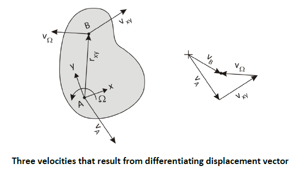
𝑣⃗𝐴 is just the translational movement of the xy-origin in the XY-frame. 𝑣⃗𝑥𝑦 is the translational motion of point B in the xy-frame, that is, on the slab. 𝑣⃗Ω is the motion of B due to the rotation of the slab.
Acceleration
By definition 𝑎⃗𝐵 = 𝑣⃗̇𝐵
We start with the three-term velocity equation in its detailed form above, so that we can see what accelerations result from what differentiations.
𝑣⃗𝐵 = 𝑣𝐴𝑋𝐼̂ + 𝑣𝐴𝑌𝐽̂ + (𝑣𝐵/𝐴−𝑥 – 𝑟𝐵/𝐴−𝑦 Ω) 𝑖̂ + (𝑣𝐵/𝐴−𝑦 + 𝑟𝐵/𝐴−𝑥 Ω) 𝑗 ̂
𝑣⃗̇𝐵 = 𝑣̇𝐴𝑋 𝐼̂ + 𝑣𝐴𝑋 𝐼̂̇+ 𝑣̇𝐴𝑌 𝐽̂+𝑣𝐴𝑌 𝐽̂̇+ (𝑣̇𝑥 − 𝑟̇𝑦 Ω − 𝑟𝑦 Ω̇) 𝑖̂+ (𝑣𝑥 − 𝑟𝑦 Ω) 𝑖̂̇+ (𝑣̇𝑦 + 𝑟̇𝑥 Ω + 𝑟𝑥 Ω̇) 𝑗̂ + (𝑣𝑦 + 𝑟𝑥 Ω) 𝑗̂
Again 𝐼̂ and 𝐽̂ belong to the fixed frame, so they don’t change and are 0. Also we can substitute in the results for 𝑖̂̇ and 𝑗̂̇ previously calculated. 𝑟̇ is 𝑣, and 𝑣̇ is .
𝑣⃗̇𝐵 = 𝑎𝐴𝑋 𝐼̂ + 𝑎𝐴𝑌 𝐽̂ + (𝑎𝑥 − 𝑣𝑦 Ω − 𝑟𝑦 Ω̇) 𝑖̂+ (𝑣𝑥 − 𝑟𝑦 Ω) Ω 𝑗̂+ (𝑎𝑦 + 𝑣𝑥 Ω + 𝑟𝑥 Ω̇) 𝑗̂ + (𝑣𝑦 + 𝑟𝑥 Ω)(−Ω 𝑖̂)
𝑎⃗𝐵 = 𝑎𝐴𝑋 𝐼̂ + 𝑎𝐴𝑌𝐽̂ + (𝑎𝑥 − 2𝑣𝑦 Ω − 𝑟𝑦 Ω̇− 𝑟𝑥 Ω2) 𝑖̂+ (𝑎𝑦 + 2𝑣𝑥 Ω + 𝑟𝑥 Ω̇− 𝑟𝑦 Ω2) 𝑗̂
This is the five-term acceleration equation.
The five accelerations, though they arose simply from applying the product rule to vector differentiation, can be ascribed definitive physical meaning. Let’s define them first with a shorthand notation and then discuss their characteristics.
1. 𝑎⃗𝐴 = 𝑎𝐴𝑋 𝐼̂ + 𝑎𝐴𝑌 𝐽̂, the acceleration of point A in the fixed XY-frame
2. 𝑎⃗𝑥𝑦 = 𝑎𝑥 𝑖̂+ 𝑎𝑦 𝑗̂, the acceleration of B within the moving, rotating xy-frame
3. 𝑎⃗𝐶 = −2𝑣𝑦 Ω 𝑖̂+ 2𝑣𝑥 Ω 𝑗̂, the Coriolis acceleration of B
4. 𝑎⃗𝑡 = −𝑟𝑦 Ω̇ 𝑖̂+ 𝑟𝑥 Ω̇ 𝑗̂, the tangential acceleration of B
5. 𝑎⃗𝑛 = −𝑟𝑥 Ω2 𝑖̂− 𝑟𝑦 Ω2 𝑗̂, the normal acceleration of B
So 𝑎⃗𝐵 = 𝑎⃗𝐴 + 𝑎⃗𝑥𝑦 + 𝑎⃗𝐶 + 𝑎⃗𝑡 + 𝑎⃗𝑛
𝑎⃗𝐴 And 𝑎⃗𝑥𝑦 are both independent accelerations and do not involve the rotation of the slab. Normally in an analysis they will have to be given or observed. The other three accelerations do involve the rotation of the slab. 𝑎⃗𝑡 involves a speed-up of the tangential velocity, 𝑣⃗Ω, simply because the spin speed is increasing…or a slow-down in 𝑣⃗Ω because the spin speed is decreasing. 𝑎⃗𝑛 is due to the constant change in direction of 𝑣⃗Ω as it seemingly rotates about A. Note that this is directed opposite to 𝑟⃗𝑥𝑦 which is 𝑟⃗𝐵/ . The third term, Coriolis acceleration, is the most puzzling and misunderstood of the five. It results from a combination of movements: movement on the slab while it is rotating. It was not even known until long after Newton developed his three laws and Euler extended them to rigid bodies.
The three accelerations involving Ω⃗ can also be cast as cross products.
3. 𝑎⃗𝐶 = 2 Ω⃗ × 𝑣⃗𝑥𝑦 the Coriolis acceleration of B
4. 𝑎⃗𝑡 = Ω⃗ ̇ × 𝑟⃗𝑥𝑦, the tangential acceleration of B
5. 𝑎⃗𝑛 = Ω⃗ × (Ω⃗ × 𝑟⃗𝑥𝑦), the normal acceleration of B
That these are equivalent to the unit-vector versions above can be seen as follows. The magnitude equivalency can be verified by inspection. The directions can be seen in that in 2-D, positive Ω⃗ and Ω⃗ point out of the slab. Pre-crossing them with a vector produces a vector that is rotated 90° to the right of the second vector in the cross-product. Also, since both Ω⃗ and Ω⃗ ̇ point in the 𝑘 ̂ direction (if they are positive), they will convert 𝑖̂-components into 𝑗̂-components and 𝑗̂-components into −𝑖̂-components. Note that 𝑎⃗𝐶 and 𝑎⃗𝑡 have y-components in the −𝑖̂-direction and x-components in the 𝑗̂-direction. With 𝑎⃗ , there is a double pre-crossing by Ω⃗ . Thus the direction is turned 180° around from 𝑟⃗𝑥𝑦.
In the second pre-cross, the x-components that had been turned into the 𝑗̂-direction get turned another 90° into the −𝑖̂-direction. Note that in the unit-vector version of 𝑎⃗𝑛 x-components stay as 𝑖̂-components, and y-components stay as 𝑗̂- components. But both are now negative
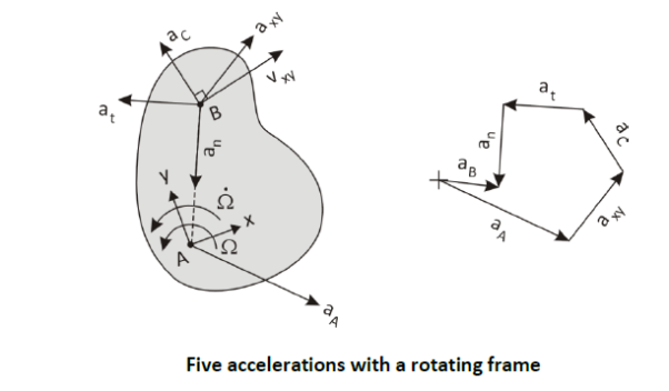
The figure above shows an example of the five accelerations. 𝑎⃗𝐴 and 𝑎⃗𝑥𝑦 are independent and could be drawn in any direction. The Coriolis acceleration is perpendicular and to the left of 𝑣⃗𝑥𝑦 since the slab is rotating counter-clockwise. 𝑎⃗𝑡 is perpendicular and to the left of the line from A to B since Ω⃗ ̇ is counter-clockwise. 𝑎⃗𝑛 leads from B back toward the apparent center of rotation at A .
Though this is explained in 2-D for visualization purposed, it is equally valid for 3-D.
Also noteworthy is that the center of rotation of the slab does not have to be at A . It does look to an observer at A as if the slab is rotating about him. But the rotation point does not even have to be fixed. It could change with time, like an instant center does, in the general case. It could even be, if we take the special case of B not moving on the slab, that B is the center of rotation. But all of the above is still true, and we can center our rotating coordinate system at any point on the slab. I would like to work out this counter-case at some point, just to demonstrate it.