UNIT-2
Resistance
2.1.1 Measurement of Low Resistance by Kelvins Double Bridge.
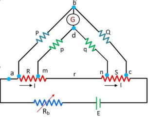
The ratio of the arms p and q are used to connect the galvanometer at the right place between the point j and k. The j and k are used to reduce the effect of connecting lead. The P and Q is the first ratio of the arm and p and q is the second arm ratio.
|
Figure 1. Kelvins Double Bridge
The galvanometer is connected between the arms p and q at a point d. The point d places at the centre of the resistance r between the point m and n for removing the effect of the connecting lead resistance which is placed between R the unknown resistance and S the standard resistance S.
The ratio of p/q is made equal to P/Q. Under balance condition zero current flows through the galvanometer. The potential difference between the point a and b is equivalent to the voltage drop between the points Eamd.
Eab = P/P+Q . Eac
Eac= I[ R + S + (p+q)r/p+q+r] -----------------------------(1)
Eamd = I[ R + p/(p+q) {(p+q)r/ p+q+r}]
Eac = I[ pr/p+q+r] ------------------------------------------(2)
Now,
For zero galvanometer deflection,
Eac = Eamd P/P+Q. I[ R + p/(p+q) { (p+q)r/ p+q+r}] = I[pr/p+q+r] R= P/Q.S + pr/p+q+r[ P/Q -p/q] |
As we known, P/Q = p/q then above equation becomes
R=P/Q.S
The equation shows that the result obtains from the Kelvin double bridge is free from the impact of the connecting lead resistance.
Key Take Aways:
A kelvin bridge or kelvin double bridge is a modified version of the Wheatstone bridge, which can measure resistance values in the range between 1 to 0.00001 ohms with high accuracy.
2.1.2 Measurement of Medium Resistance
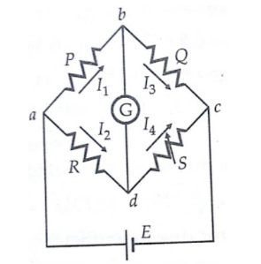
Wheatstone bridge is an important device used in the measurement of medium resistances. The figure below shows the basic circuit of a Wheatstone bridge.
It has four resistive arms, consisting of resistances P, Q R and S together with a source of emf that is battery and null detector galvanometer G or another sensitive current meter. The current through the galvanometer depends on the potential difference between points c and d.
The bridge is said to be balanced when there is no current through the galvanometer or when the potential difference across galvanometer is zero.
The balanced condition occurs when voltage from point b to point a equals to voltage from point d to point b or by referring to the other battery terminal when the voltage from point d to point c equals the voltage from point b to point c.
|
Figure 2. Wheatstone bridge for measurement of medium resistance.
For a balanced condition, we can write,
I1 P = I2 R ---------------------(1)
For the galvanometer current to be zero, the following conditions also exist:
I1 = I3 = E/P+Q-----------------------------(2)
I2 = I4 = E/R+S ---------------------------------(3)
where E = emf of the battery
Combining the above three equations we get,
P/P+Q = R/R+S --------------------------------(4)
from which Q.R = P.S ----------------------------------------------------------------(5)
If three resistance are known, the unknown resistance can be obtained by
R = S*(P/Q)
where R is the unknown resistance, S is called the 'standard arm' of the bridge and P and Q are called the 'ratio arms'.
Key Take Aways:
The Wheatstone Bridge is used to measure unknown resistance values as means of calibrating measuring instruments, voltmeters, ammeters, and so on by the use of a long resistive slide wire.
2.1.3 Measurement of High Resistance
Megohm Bridge Method:
|
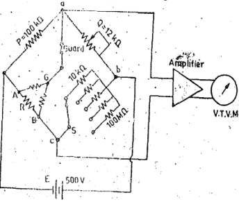
Figure 3. Megaohm Bridge
Figure 3. shows the circuit of Megaohm bridge which includes power supplies, bridge members, amplifiers and indicating instrument. It has the range form 0.1MΩ to 10 6 MΩ
Sensitivity for balancing against high resistance is obtained by use of adjustable high voltage supplies of 500V or 1000V and the use of null indicating arrangement such as high gain amplifier with vacuum tube or transistor voltmeter or cathode ray oscilloscope. Since the unknown resistance R=PS/Q , the arm Q is made tampered so that the dial calibration is approximately logarithmic in main decade 1-10, Arm S gives5 multipliers 0.1,1,10,100 and 1000. The junction of ratio arms P and Q is brought on the main panel and is designated as “guard terminal”.
Key Take Aways:
Megaohm Bridge is another method for measure of high resistance
2.1.4 Measurement of Resistance of Insulating Materials
We define insulation resistance as the ratio of applied direct voltage across an insulation to the corresponding current through it.
The measurement of insulation resistance can be conducted with an external dc supply.
Here we take voltage and current reading with the help of a dc voltmeter and a micro ranged dc ammeter , respectively.
R = V/I
Hence, we can calculate the insulation resistance with the help of ohms law.
When we use direct indicating ohmmeter of simply megger, the leads of the instrument are connected across the insulator to be tested. After driving the instrument, the value of insulation resistance is indicated on the analog or digital dial of the instrument directly.
Key Take Aways:
We define insulation resistance as the ratio of applied direct voltage across an insulation to the corresponding current through it.
2.1.5 Portable Resistance Testing set(megohmmeter)
Megohmmeters, sometimes called meggers, provide quick and easy method to determine the condition of the insulation on wire, generators, and motor windings.
A megohmmeter is an electric meter that measures high resistance values by sending a high voltage signal into the object being tested
The function of megohmmeter is to measure high resistance values by sending a high voltage signal into the object being tested. It performs more complex testing and recording of measurements.
Key Take Aways:
Portable resistance tester is ideal for low-resistance, measurement and testing of large transformers and motors ·
2.1.6 Measurement of Insulation resistance when Power is ON
Two voltage measurements are done first with voltmeter connected between positive main and the ground as shown in fig(a) the second with voltmeter connected between negative main and ground as shown in figure (b).
|
Figure4. Measurement of insulation resistance when power is ON.
Let
Ri =insulation resistance between positive main and earth,
R2=insulation resistance between negative main and earth,
Rn=resistance of the voltmeter,
Vi= measured voltage between positive main and earth,
V2=measured voltage between negative main and earth, and
E=measured voltage between positive main and negative main .
Jf his the current flowing from positive main to negative main in Fig. (a),
We have E=(R1Rv/R1+Rv + R2) I1 = (R1Rv+R1R2+R2Rv/R1+Rv)I1 and V1=(R1Rv/R1+Rv) I1 E/V1 = R1Rv+R1R2+R2Rv/R1Rv------------------------------------(1) E/V2 = R1Rv+R1R2+R2Rv/R2Rv-------------------------------------(2) From (i) and (ii) V2/V1 = R2/R1 or R2=R1. V2/V1 Substituting this value of R2 in (i) E/V1 = R1.V2/V1(R1+Rv) +R1Rv/ R1Rv = R1.V2/V1 + Rv.V2/V1 + Rv/ Rv R1=Rv. E-(V1+V2)/V2-------------------------------------------------------------(3) R2 = RvE-(V1+V2)/V1 -----------------------------------------------------------(4) |
Key Take Aways:
The test, therefore, determines how effective the dielectric (insulation) is in resisting the flow of electrical current.
2.1.7 Measurement of Resistance of Earth Connections.
Four Point Method (Wenner Method)
|
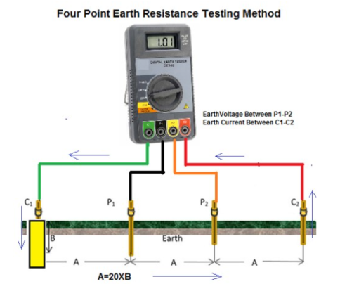
Figure 5. Four Point Earth resistance Testing Method
- Press START and read out the resistance value. This is the actual value of the ground Resistance of the electrode under test.
- Record the reading on Field Sheet at the appropriate location. If the reading is not stable or displays an error indication, double check the connections. For some meters, the RANGE and TEST CURRENT settings may be changed until a combination that provides a stable reading without error indications is reached.
- The Earthing Tester has basically Constant Current generator which injects current into the earth between the two current terminals C1 (E) and C2 (H).
- The potential probes P1 & P2 detect the voltage ΔV due to the current injected in the earth by the current terminals C1 & C2.
- The test set measures both the current and the voltage and internally calculates and then displays the resistance. R=V/I
- If this ground electrode is in parallel or series with other ground rods, the resistance value is the total value of all resistances.
- Ground resistance measurements are often corrupted by the existence of ground currents and their harmonics.
- To prevent this use Automatic Frequency Control (AFC) System. This automatically that selects the testing frequency with the least amount of noise enabling you to get a clear reading.
- Repeat above steps by increasing spacing between each electrode at equal distance and measure earth resistance value.
- Average all readings
Key Take Aways:
- An effective way of decreasing the electrode resistance to ground is by pouring water around it.
2.2.1 Measurement of self-inductance by Ammeter and Voltmeter.
|
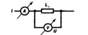
Figure 6. Diagram of the measurement of inductance by the “voltmeter-ammeter” method:(A) ammeter, (V) voltmeter.
The “voltmeter-ammeter” method as shown in Figure is used for measuring relatively large inductances (from 0.1 to 1,000 henrys [H]) when the resistance of the windings is significantly lower than the inductance.
Here Lx = U/(π f · I)
where U is the voltage, I is the current in the circuit whose inductance is being measured, and f is the frequency of the alternating current, usually 50 hertz (Hz).
Such inductance meters have an error of 2–3 percent.
An AC measuring bridge for frequencies of 100, 400, and 1,000 Hz with standard capacitance or, much less frequently ,standard inductance as shown in figure Figure 2 is the main component of inductance meters.
When the bridge is balanced,
rx = (R1· R2)/R3Lx = Cs· R1· R2
where rx is the ohmic resistance of the wire of the inductance coil winding. Bridge measurement methods have an error of 1–3 percent; the range of measurement is 0.1 to 1,000 H.
|
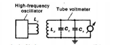
Figure 7. Diagram of resonance method of inductance measurement: (Lc) coupling loop, (Lx) inductance being measured, (Cc) self-capacitance of coil, (Cs) standard capacitance.
Key Take Aways:
The “voltmeter-ammeter” method is used for measuring relatively large inductances.
2.2.2 AC Bridges (Maxwells, Hay and Anderson)
2.2.2.1 Maxwells Bridge
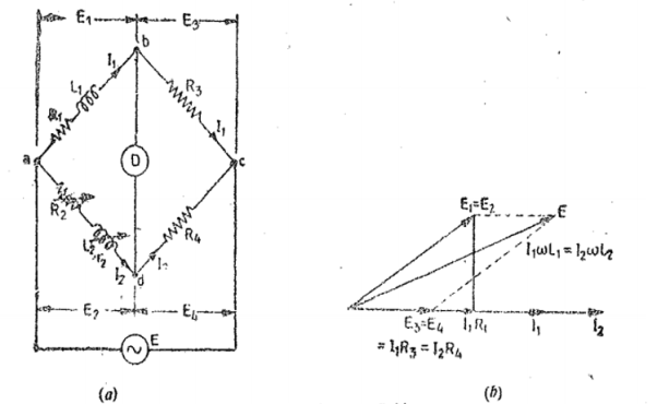
This bridge circuit measures an inductance by comparison with a variable standard self-inductance. The connections and the phasor diagrams for balance conditions are shown in Fig. Let
Li =unknown inductance of resistance Ri,
L2=variable inductance of fixed resistance r2,
Ra=variable resistance connected in series with inductor L2, and
R3,R4=known non-inductive resistances .
|
Figure 8 . Maxwells Inductance Bridge
At balance
L1 = R3/R4 L2
R1 = R3/R4 (R2+r2)
2.2.2.2 Hays Bridge
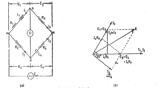
The Hay's bridge is a modification of Maxwell's bridge. The block diagram and the phasor diagram for this bridge are shown in Figure. The bridge uses a resistance in series with the standard capacitor.
|
Figure 9.Hays Bridge
Let L1 =unknown inductance having a resistance Ri, R2, Ra.
R4=known non-inductive resistances, and
C4=standard capacitor.
At balance,
(R1+jwL1)(R4-jwC4) = R1R3 or
R1R2+L1/C4+jwL1R4-jR1/wC4=R2R3
Separating the real and imaginary terms we obtain
R1R4+L1/C4=R2R3 and L1 =R1/w 2 R4C4 Solving the two equations we have L1 = R2R3C4/1+w 2 C42 R4 2 ---------------(1) R1 = w 2 R2 R3 R4 C4 2/ 1+ w 2 c4 2 R4 2 ----------------------------------------------(2) The Q factor of the coil is Q=wL1/R1 = 1/wC4R4-------------------------------------(3) |
2.2.2.3 Anderson Bridge
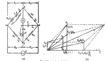
This method is applicable for precise measurement of self-inductance over a very wide range of values. Fig. shows the connections. and the phasor diagram of the bridge for balanced conditions.
|
Figure 10. Anderson Bridge
Let L1= self-inductance to be measured.
R1 = resistance of self -inductor
r 1 = resistance connected in series with self-conductor
C = fixed standard capacitor
R,R2,R3,R4 are known non inductive resistances.
At balance I1=I3 and I2=Ic+I4 I2R3 =Ic x 1/jwC Ic = I1jwCR3 Writing the other balance equation I1(r1+R1+jwL1) = I2R2+Icr and Ic(r+1/jw) = (I2-Ic) R4. Substituting the values of Ic in the above equation we get I1(r1+C1+jwL1)=I2R2+I1jwC or I1(r1+R1-jwCR2r) =I2R2 ------(i) And jwCR2 I1(r+1/jwC) = (I2-I1jwcR2) R4 or I1(wCR2r+jwCR3R4+R3) = I2R4—(ii) From (i) and (ii) we get I1(r1+R1+jwL1-jwCR2r) = I1(R2R3/R4+jwCR2R3r/R4 +jwCR3R2) |
Equating real and imaginary terms
R1=R2R3/R1 -r1
And L1=CR3/R4[r(R4+R3) +R2R4
Key Take Aways:
AC bridges are the circuits that are used for the measurement of electrical quantities such as inductance, capacitance, resistance
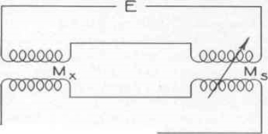
Mutual inductance is measured by using standard of comparison a mutual inductance, a self-inductance, or capacitance. When the standard mutual inductance is continuously variable and of such a range that it can be made equal to the unknown mutual inductance, the Felici mutual-inductance balance is the simplest method.
|
Figure 11. Felici mutual-inductance balance
In Figure the primaries of both mutual inductances, unknown and standard, are connected in series to a power source. Their secondaries are also connected in series to a suitable detector, head telephones, or oilier a-c operated meter, in such direction that their induced voltages oppose. The standard is then varied until a balance is obtained.
The error in this measurement is essentially that of the standard, provided that the capacitive reactance’s between the coils of the mutual inductances are large compared with their mutual reactance’s and that the impedance of the detector is small.
Key Take Aways:
Mutual inductance is measured by using standard of comparison a mutual inductance, a self-inductance, or capacitance
2.4.1 Measurement of Capacitance by Ammeter and Voltmeter
|
Figure 12. Ammeter and Voltmeter
1.Set the power supply to approximately V.
2. Connect the free terminal to the power supply and wait a few seconds to charge the capacitor.
3. Measure the potential difference across the capacitor with the voltmeter. Make sure to disconnect the voltmeter after you finish your measurement.
4. Record the current through the ammeter, and then disconnect the terminal from the power supply. The capacitor will begin to discharge.
Key Take Aways:
Capacitance can be measured by ammeter and voltmeter.
2.4.2 AC Bridges (Owens, Schering and Weins bridge)
2.4.2.1 Owens Bridge
|
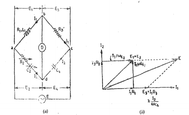
Figure 13.Owens Bridge
This bridge is used for measurement of inductance in terms of capacitance . Figure shows the block diagram and phasor diagrams. Under balance conditions
L1 = unknown self-inductance or resistance R1 R2=variable non inductive resistance R3= fixed non inductive resistance C2 = variable standard capacitor C4= fixed standard capacitor At balance (R1+jwL1)(1/jwC4) = (R2+1/jwC2) R3 Separating real and imaginary terms we get L1 = R2R3C4 R1 = R3.C4/C2 |
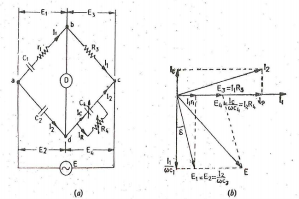
2.4.2.2 Schering Bridge
|
Figure 14. Schering Bridge
The connection and phasor diagram of the bridge under balance conditions are shown in figure.
Let C1 = capacitor whose capacitance is to be determined r 1 = series resistance representing the loss in capacitor C1 C2 = standard capacitor. R3 = non-inductive resistance C4= variable capacitor R4 = variable non-inductive resistance in parallel with variable capacitor C4. At balance (r1+1/jwC1)(R4/1+jwC4R4) = 1/jwC2.R (r1+1/jwC1) R4 = R3/jwC2(1+jwC4R4) r 1 R4 -jR4/wC1=-j R3/wC2+R3R4C4/C2 |
Equating real and imaginary terms we obtain
r 1 = C4/C3 .R3
C1 = R4/R3. C2
Two independent balance equations are obtained if C4 and R4 are chosen as the variable elements.
Dissipation factor D1 =tan ɸ=wC1r1=w.R4/R3 .C2.C4/C2 .R3 = wC4 R4 |
2.4.2.3 Weins bridge
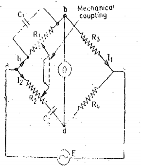
Weins bridge is primarily used to determine the frequency not only for AC bridge but for other circuits.
|
Figure15. Weins bridge
At balance (R1/1+jwC1R1) R4 = (R2-j/wC2) R3 R4/R3 = R3/R1 + C1/C2 + j(wC1R2 -1/wC2R1) Equating real and imaginary terms we get R4/R3 = R2/R1 +C1/C2 And wC1R2 -1/wC2R1 =0 from which w=1/√R1R2C1C2 and Frequency f =1/2π√R1R2C1C2 . |
In most Wein bridge the components are chosen such that
R1=R2=R and C1=C2=C
Therefore R4/R3 = 2
F=1/2πRC
Key Take Aways:
AC bridges are the circuits that are used for the measurement of electrical quantities such as inductance, capacitance, resistance. Along with these an ac bridge allows us to measure storage factor, loss factor, dissipation factor etc. AC bridges operate with only AC signal.
2.4.3 Screening of Bridge Components
Screening of bridge components is required to eliminate errors in A.C bridges due to stay conductance effects , mutual inductance effects , stray capacitance effects and residues in components .
2.4.4 Wagner Earthing Device
|
Figure 16. Wagner Earthing device
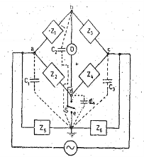
Figure shows the connections of the device for use in conjunction with the general form of bridge network, in which Z1, Z2, Za and Z4 are the impedances of the bridge arms. Z5 and Z6 are the two variable impedances of the Wagner earth branch, the centre point of which is earthed as shown. · These impedances may consist of variable resistances and capacitances like those used in the arms. of the bridge proper · The two impedances Z5 and Z6 must be capable of forming a balanced bridge with Z1 and Za or Z2 and Z4 and can be a duplicate of either pair of arms C1,C2, C3 and C4 are the stray earth capacitances appearing at the apexes of the bridge and D is the detector.
If tile switch S is on contact d, balance of the bridge may be obtained by adjustment of the impedances Z2 and Z4. The presence of the earth capacitances will prevent true balance being obtained, but a point of minimum sound can be obtained.
Key Take Aways:The Wagner earthing device is used for removing the earth capacitance from the bridges.
References:
- Elements of Electronic Instrumentation and Measurement – by Carr
- Basic Electrical, Electronics and Measurement Engineering Paperback – 1 January 2019 by U.A Bakshi and A.P Godse.
- Electrical and Electronic Measurement and Instrument Paperback R.K Rajput.
- Electrical & Electronic Measurements B. P. Patil, Pooja Mogre (Bisen).
- Electronic Measurements and Instrumentation By A.K. Sawhney.
