Galvanometer
3.1.1 Construction
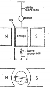
Figure 1. d'Arsonval Galvanometer
The construction of galvanometer consists of
- Moving coil:
It is the current carrying element. It is either rectangular or circular in shape and consists of several turns of fine wire. This coil is suspended so that it is free to tum about its vertical axis of symmetry. It is arranged in uniform, radial, horizontal magnetic field in the air gap between pole pieces and armature (iron core) of a permanent magnet. The armature (iron core) is spherical in shape if the coil is circular but is cylindrical if the coil is rectangular.
2. Damping
There is a damping torque present owing to production of eddy currents in the metal former on which the coil is mounted. Damping is also obtained by connecting a low resistance across the galvanometer terminals.
3. Suspension
The coil is supported by a fiat ribbon suspension which also carries current to the coil. The other current connection in a sensitive galvanometer is a coiled wire. This is called the lower suspension and has a negligible torque effect. This type of galvanometer must be levelled carefully so that the coil hangs straight and centrally without rubbing the poles or the soft iron cylinder.
4. Indication.
The suspension carries a small mirror upon which a beam of light is cast. The beam of light is reflected on to a scale upon which the deflection is measured. This scale is usually about 1 metre away from the instrument, although 1 /2 metre may be used for greater compactness.
3.1.2 Theory and Principle of Operation of Galvanometer
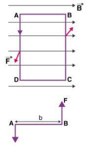
Initially consider a single turn ABCD of the rectangular coil having a length l and breadth b. This is suspended in a magnetic field of strength B such that the plane of the coil is parallel to the magnetic field.
Since the sides AB and DC are parallel to the direction of the magnetic field, they do not experience any effective force due to the magnetic field. The sides AD and BC being perpendicular to the direction of field experience an effective force F given by F=BI.l
|
Figure 2. Current carrying loop in magnetic field.
We know that torque τ = force x perpendicular distance between the forces
τ = F × b
Substituting the value of F we already know,
Torque τ acting on single-loop ABCD of the coil = BIl × b
Where lx b is the area A of the coil,
Hence the torque acting on n turns of the coil is given by
τ = nIAB
The magnetic torque thus produced causes the coil to rotate, and the phosphor bronze strip twists. In turn, the spring S attached to the coil produces a counter torque or restoring torque kθ which results in a steady angular deflection.
Under equilibrium condition:
kθ = nIAB
Here k is called the torsional constant of the spring (restoring couple per unit twist). The deflection or twist θ is measured as the value indicated on a scale by a pointer which is connected to the suspension wire.
θ= ( nAB / k)I
Therefore θ ∝ I
Key Take Aways:
It is one of the common measuring instruments. The galvanometer is used for detecting the presence of small voltages or currents to indicate zero current in applications like bridge circuit.
A = l × b
When current flows across the coil, then the torque is developed . The magnitude of the torque is given by τ = NiBA
Assume that the flow of current across the coil for each minimal time is dt and so the change in current is represented as
τ dt = NiBA dt
When there is current flow across the coil for a time of ‘t’ seconds, then the value is represented as
ʃ0t τ dt = NBA ʃ0t idt = NBAq
where ‘q’ is the total amount of charge that flows across the coil. The inertial moment that exists for the coil is shown as ‘I’ and the coil’s angular velocity is shown as ‘ω’.
The below expression provides the angular momentum of the coil and it is lω. It is like the pressure that is applied to the coil.
By multiplying the above two equations, we get
lw = NBAq
Also, the kinetic energy across the coil will have deflection at ‘ϴ’ angle and the deflection will be restored using the spring. It is represented by
Restoring torque value = (1/2)cϴ2
Kinetic energy value = (1/2)lw2
As the coil’s restoring torque is similar to the deflection then
(1/2)cϴ2 = (1/2)lw2
cϴ2 = lw2
Also, the periodic oscillations of the coil is shown as below
T = 2π√(l/c)
T2 = (4π2l/c)
(T2/4π2) = (l/c)
(cT2/4π2) = l
Finally, (ctϴ/2π) =lw = NBAq
q = (ctϴ)/NBA2π
q = [(ct)/NBA2π] * ϴ)
Assume that k = [(ct)/NBA2π
Then q = k ϴ
So, ‘k’ is the constant term of the ballistic galvanometer.
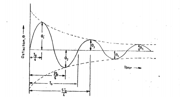
Figure 3. Variation of deflection of ballistic galvanometer
Logarithmic decrement λ = π  td/To
td/To
For cases where damping is small Td =To and λ = πζ
π D/Do = π D/2√KJ
Hence the equation is given by
 1 =
1 =  e - λ/2 -------------------------------------(1)
Hence  2 =
2 =  Q e -3λ/2 -------------------------------------(2)
 =
=  –(2n-1)λ/2 -----------------------------------------(3)
Let us examine the case when the galvanometer is free from damping that is D=0 . The equation of motion of undamped galvanometer is derived as
 =AQ sin 2π/To .t --------------------------------------------(4)
Amplitude of swings of undamped oscillations is given by
 o = AQ sin 2π/To . To/4 = AQ
Hence we write
 =
=  e -λ/2
 =
=  e -3λ/2
 =
=  e–(2n-1)λ/2
Logarithmic decrement is logarithm of ratio of successive swings.
Logarithmic decrement λ = log (
Now the ratio of successive swings is :  1/
1/ 2 = e -λ/2 / e -3λ/2 = e λ
Similarly
 /
/ = e λ
= e λ
-------
From the above we get
|
Logarithmic decrement is λ = 1/n- log e ( )
)
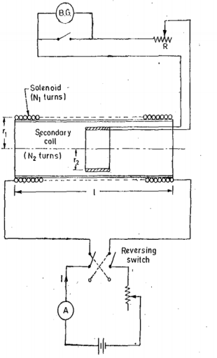
Figure 4. Calibration of galvanometer with mutual inductance
Using Mutual Inductance:
The mutual inductance is usually in the form of standard solenoid with secondary coil. A standard solenoid consists of long coil wound on a cylinder. The length of the cylinder is large as compared with its diameter. At the centre of solenoid, a secondary coil is placed. The axial length of the secondary coil is small.
The secondary coil is connected to the ballistic galvanometer. When a current is passed through solenoid the field strength at the centre is
H = N1I/l cos  = N1 I / l . l/2 / √ (l/2) 2 + (r1) 2
Where N1 = number of turns of the solenoid
I = current through the solenoid
l=length of the solenoid
r1 = mean radius of the solenoid.
Flux density at the centre of solenoid B =  H
H
Flux linking with secondary coil ɸ = B x area of secondary coil = B x π r 2 =  Br2 2
Br2 2
= π μo H r2
Where r2 = mean radius of secondary coil.
Let N2 be the number of turns in the secondary coil.
Therefore, flux linkages of secondary coil ɸ2 = N2 ɸ = 2 πμoN2Hr2 2
Suppose  i is the throw of the galvanometer
Therefore, constant of galvanometer in terms of flux linkages
Kɸ = 2 μoN2 Hr2 2 /
  weber turn per radian
2 μoN2 . N1 Ir2 2 /
  √ (l/2) 2 + (r12) . 1/
  =
=  μoN2 . N1 Ir2 2 / √(l/2) 2 + (r1 2)
The equivalent circuit with mutual inductance is given by
Kɸ = 2MI/ weber turn per radian
Suppose the change in flux linkage takes place in time t .
Therefore, emf induced in the secondary coil is given by
Rate of change in flux linkages = -d /dt
/dt
= 2 μoN2 Hr2 2 / t
This emf sends a current I through the galvanometer
i = 2 μoN2 Hr2 2 /R t
where R is the galvanometer circuit resistance.
Charge passing in time t
Q=it = 2 μoN2 Hr2 2 /R
But Q = Kq 
Where kq = constant of galvanometer in coulomb per radian
Kq = Q/ = |
Thus, the galvanometer constant can be obtained in terms of coulomb per radian.
Key Take Aways: The galvanometer which is used for estimating the quantity of charge flow through it is called the ballistic galvanometer.
Assume a galvanometer with very short needle and so placed with respect to its coils that the magnetic field produced by a current circulating in them is sensibly uniform in the neighborhood of the needle with its lines of force at right angles to. The field is proportional to the current I, so that it may be denoted by G. Then G is galvanometer constant.
Magnetic field by Galvanometers
A galvanometer is not used to measure a current, but rather to detect whether the current is flowing and in which direction.
If we have a small coil of area A, N turns, resistance R, we could place the coil perpendicular to a magnetic field B, and then connect the coil to a ballistic galvanometer. Then, suddenly remove the coil from the so that the flux through the coil goes from AB to zero. While the flux through the coil is changing, and EMF will be induced, equal to NAB and consequently a current will flow momentarily through the coil of magnitude
I = NAB/R+r’ where r is the resistance of the galvanometer. Integrate this with respect to time with initial condition Q=0 when t=0 and we find the total quantity of electricity that flows through the galvanometer
Q = N AB / R + r’
Since Q can be measured from the amplitude of the galvanometer motion , the strength of the magnetic field B is determined.
Measurement of flux by Galvanometers
The fluxmeter is the advanced form of the ballistic galvanometer which has advantages like the meter which has low controlling torque and heavy electromagnetic damping.
|
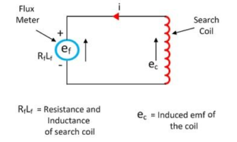
Figure5. Flux meter
The terminals of the fluxmeter are connected across the search coil as shown in the figure below. The flux linking with the coil is varied by either removing it from the magnetic field or by reversing the field of the magnet. The change of the flux induces the electromotive force in the coil. This emf induces the current in the search coil and sends it through the flux meter. Because of the current, the pointer of the fluxmeter deflects, and their deflection is directly proportional to the change in the value of flux linkages.
Key Take Aways:
Galvanometer is the instrument used for measuring a small electrical current or a function of the current by deflection of the moving coil. The deflection is the mechanical rotation derived from forces resulting from the current.
3.7.1 Construction
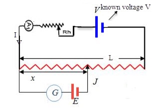
The potentiometer consists of a long resistive wire L made up of magnum or with constantan and a battery of known EMF V. This voltage is called driver cell voltage. Connect the two ends of the resistive wire L to the battery terminals as shown below;
One terminal of another cell whose EMF E is to be measured is at one end of the primary circuit and another end of the cell terminal is connected to any point on the resistive wire through a galvanometer G.
|
Figure 6.Construction of Potentiometer
The basic working principle of this is based on the fact that the fall of the potential across any portion of the wire is directly proportional to the length of the wire, provided wire has a uniform cross-sectional area and the constant current flowing through it
Let the current through the potentiometer is I and R is the total resistance of the potentiometer.
Then by Ohms law V=IR
We know that R= ῥL/A
Thus, V= I ῥL/A
As ῥ and A are always constant and current I is kept constant by a rheostat.
So L ῥ/A=K (constant)
Thus, V= KL.
3.7.2 Theory and Principle of operation of DC Potentiometer
3.7.2.1 Crompton Potentiometer
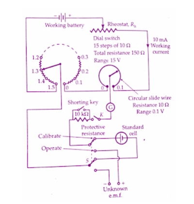
Figure 7. Crompton Potentiometer
This potentiometer is provided with a double throw switch which allows the connection of either the standard cell or the unknown emf to be applied to the working circuit.
A key and a protective resistance usually about 10 KΩ is used in the galvanometer circuit. To operate the galvanometer at its maximum sensitivity provision is made to short the protective resistance for the balance conditions.
3.7.2.2.Vernier
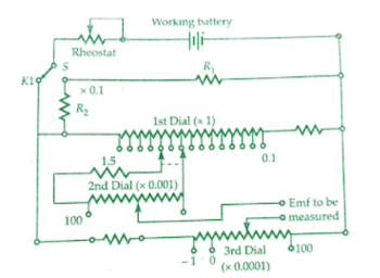
This potentiometer uses the Kelvin Varley arrangement shown below. There are three measuring dials. The first dial measures upto 1.5 V (on the XI range) in steps 0.1 V : the middle dial has 102 studs and reads upto 0.1 V in steps of 0.001 V; the third dial also has 102 studs and reads from - 0.0001 V to 0.001 V in steps of 0.00001 V (i.e., 10 µV).There is no slide wire. The resistances of the middle dial shunt two of the coils of the first dial.
The moving arm of middle dial carries two arms spaced two studs apart. In actual practice the resistance of the second dial is greater than that between two studs in the main (first) dial, so that the voltage drop across the second dial is greater than 0.1 V.
|
Figure 8. Duo range vernier potentiometer
3.7.2.3 Constant Resistance
Electrical resistance is measured by either of two methods: constant current or constant voltage.
The constant current technique sources a known current through an unknown resistance and hence the resulting voltage is measured. This technique is generally used for resistance values below 200M ohms.
The constant voltage technique sources a known voltage across an unknown resistance and measures the resulting current.
3.7.2.4 Deflection Potentiometer
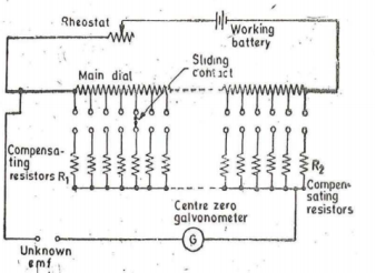
Figure9. Deflectional Potentiometer
1n this potentiometer only one or two main dials, consisting of decade resistance boxes, are used. A centre zero type galvanometer is included in the circuit to indicate deflection. The galvanometer circuit includes a set of compensating resistors R1, R2. The values of the compensating resistors is such that the resistance of the potentiometer circuit, is viewed from the terminals where the unknown emf is applied, remains constant irrespective of the position of the sliding contacts.
This means that current through the galvanometer will always be proportional to the out of balance current whatever may be the setting of the main dials. Thus, the galvanometer scale can be calibrated to read the out of balance emf directly. The value of the · unknown emf is obtained by adding the galvanometer reading to the main dial setting. The main dial setting is kept nearly equal to the emf being measured. The potentiometer is used to monitor the value of temperature where a thermocouple· is employed. The output of the thermocouple is fed to the unknown emf terminals.
Key Take Aways:
The potentiometer is a simple device used to measure the electrical potentials
3.8.1 Drysdale -Tinsley
|
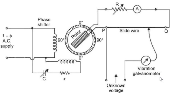
Figure 10. Drysdale-Tinsley Potentiometers
The working of Drysdale a.c. potentiometer is as under :
(1) First, the a.c. potentiometer is standardised which means it is made direct reading. For this purpose, the slide-wire circuit is connected to d.c. supply and the standard current is obtained by using a standard cell. This standard current makes the potentiometer direct reading and is measured by a dynamometer ammeter which is included in the battery supply circuit of the potentiometer. The ammeter remains connected for a. c. operation because the r.m.s. value of current in the slide-wire must be maintained at the same
(2) Once the a.c. potentiometer is standardised, the d.c. supply is removed, and the slide-wire is connected to the rotor winding of the phase-shifting circuit. The r.m.s. value of alternating current in the slide-wire is made the same as on the d.c. supply. The Balance is obtained by varying the position of slide-wire contact and position of the phase-shifting rotor. When the vibration galvanometer reads zero, it means that balance is achieved. Now, slidewire reading gives the magnitude r 'of the unknown a.c. voltage and the rotor position its phase angle θ. Therefore, the unknown a.c. voltage is represented as V∠θ.
3.8.2 Gall-Tinsley Potentiometer
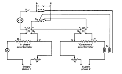
The Rheostat’s r and R’ provide respective potentiometers for the adjustment of current. By using different arrangement, the supply for the potentiometer is obtained.
A vibration galvanometer VG is tuned to the supply frequency and connected in series with the switch K and electrodynamometer type ammeter.
|
Figure. Gall-Tinsley Potentimeter
The emf to be measured is connected across the terminals A-A’ using selector S3. Sliding contects of both potentiometers are adjusted till the contacts of both the potentimeters are adjusted till null deflection is obtained.
Under balance condition the in-phase component of the unknown emf is obtained from in-phase potentiometer while the quadrature component of the unknown emf is obtained from quadrature potentiometer.
If needed the polarity of the test voltage may be reversed by using sign changing switches S1 and S2 to balance the potentiometer.
Key Take Aways:
The potentiometer which is used for measuring the phase and the magnitude of the unknown emf by comparing it with the known emf such type of potentiometer is known as the AC potentiometer.
References:
- Elements of Electronic Instrumentation and Measurement – by Carr
- Basic Electrical, Electronics and Measurement Engineering Paperback – 1 January 2019 by U.A Bakshi and A.P Godse.
- Electrical and Electronic Measurement and Instrument Paperback R.K Rajput
- Electrical & Electronic Measurements B. P. Patil, Pooja Mogre (Bisen)
- Electronic Measurements and Instrumentation By A.K. Sawhney
