UNIT 1
FUNDAMENTALS OF AC MACHINE WINDINGS
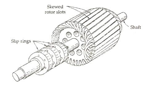
Fig 1: Induction motor (outer winding)
A three phase Induction motor mainly consists of two parts called as the Stator and the Rotor. The stator is the stationary part of the induction motor, and the rotor is the rotating part. The construction of the stator is similar to the three-phase synchronous motor, and the construction of rotor is different for the different machine.
1.1.2 Construction of Stator
The stator is built up of high-grade alloy steel laminations to reduce eddy current losses. It has three main parts, namely outer frame, the stator core and a stator winding.
1.1.3 Outer frame
It is the outer body of the motor. Its main function is to support the stator core and to protect the inner parts of the machine. For small machines, the outer frame is casted, but for the large machine, it is fabricated. The figure below shows the stator construction.
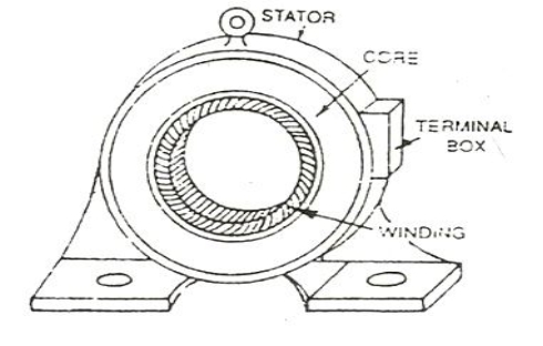
Fig 2: Induction motor inner winding
The stator core is built of high-grade silicon steel stampings. Its main function is to carry the alternating magnetic field which produces hysteresis and eddy current losses. The stampings are fixed to the stator frame. Each stamping are insulated from the other with a thin varnish layer. The thickness of the stamping usually varies from 0.3 to 0.5 mm. Slots are punched on the inner side of the stampings.
Construction of an induction motor
1.1.5 Stator windings
1. The core of the stator carries three phase windings which are usually supplied from a three-phase supply system.
2. The six terminals of the windings (two of each phase) are connected in the terminal box of the machine.
3. The stator of the motor is wound for a definite number of poles, depending on the speed of the motor.
4. If the number of poles is greater, the speed of the motor will be less and if the number of poles is less than the speed will be high.
1.1.6 Physical arrangement of windings in stator are-
Pre-manufactured coils can be inserted into the stator slots one by one to form a three-phase distributed winding
All the windings are in a single-speed three-phase motor design.
Key Takeaways:
1. The construction of the stator is similar to the three-phase synchronous motor
2. The stator is built up of high-grade alloy steel laminations to reduce eddy current losses.
3. For small machines, the outer frame is casted, but for the large machine, it is fabricated
4. The stator core is built of high-grade silicon steel stampings.
5. If the number of poles is greater, the speed of the motor will be less
6. All the windings are in a single-speed
1.2.1 What is cylindrical rotor? (Motor)
1. It is the moving part in an electromagnetic system of the motor, generator and an alternator. It is also called as the Flywheel, rotating magnetic core, an alternator. In an alternator, it includes permanent magnets that move approximately to the iron plates of the stator to produce an AC (Alternating Current).
2. It uses existing motion for its function. The rotation of this can be occurred because of the interaction between magnetic fields & the windings which generate torque in the region of the axis.
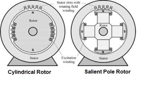
Fig 3: Cylindrical and Salient pole rotor
1.2.2 Construction and Working Principle of a Rotor
1. In a three-phase induction motor, once an AC is applied to the rotor then the windings of stator strengthen to generate a rotary magnetic flux. The flux generates a magnetic field in the air gap among the stator & the rotor to induce a voltage for generating the current throughout the bars. The circuit of this can be shorted & the flow of current will be in the conductors.
2. The act of the rotary flux & the current generates a force to generate a torque to begin the motor. The rotor in an alternator can be designed with a wire coil enclosed in the region of an iron core.
3. The magnetic component of this can be made with the laminations of the steel to assist stamping conductor slot to exact sizes & shapes. Whenever the current travels in the coil in a magnetic field then it creates a field current in the region of the core.
4. The strength of the field current mainly controls the level of power in the magnetic field. DC (direct current) drives the field current in the direction of the wire coil through a set of slip rings & brushes.
5. Similar to any magnet, the magnetic field generated will include two poles like south & north. The direction of the motor in the clockwise can be controlled through the magnets & magnetic fields fixed in this design, which allows the motor to run in a counter clockwise direction.
1.2.3 Physical arrangement of windings in cylindrical rotor are-
1. The windings for rotor are less complex than stator.
2. The windings of a rotor are less insulated.
3. The size of the cylindrical rotor winding is small as it does not need to transmit huge current through it.
Key Takeaways:
1. It includes permanent magnets that move approximately to the iron plates of the stator to produce an AC.
2. The strength of the field current mainly controls the level of power in the magnetic field
3. The rotor in an alternator can be designed with a wire coil enclosed in the region of an iron core
4. The size of the cylindrical rotor winding is small as it does not need to transmit huge current through it.
1. Because stators are cylindrical, the slots are shaped like wedges. The number of slots depends on how many phases of power are provided to the coil windings.
2. A basic single-phase motor usually has four slots that contain two pairs of coil windings, each offset by 90 degrees; a basic three-phase motor has six slots with three pairs of coil windings, each pair offset by 120 degrees.
3. To complicate matters, multiples of pole pairs can be utilized to increase the corresponding number of slots.
4. Some of the greatest challenges for a custom stator manufacturer are related to maximizing the amount of copper wire inserted into each slot (commonly referred to as “slot fill”) to maximize torque output.
5. Stator manufacturing is based on relatively simple principles but stators are inherently difficult to build.
6. Beyond the physical design limits and the question of how much slot fill is appropriate for the application, engineers have to account for manufacturability.
7. To balance these requirements, engineers must rely on proven design practices and custom manufacturing techniques.
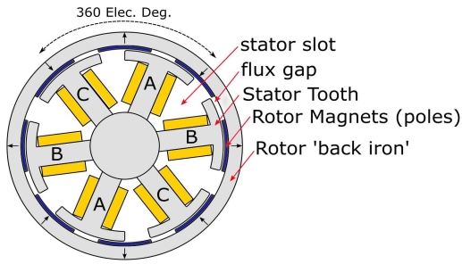
Fig 4: Slots of diagram
Key Takeaways:
1. Multiples of pole pairs can be utilized to increase the corresponding number of slots.
2. Stator manufacturing is based on relatively simple principles but stators are inherently difficult to build.
3. The number of slots depends on how many phases of power are provided to the coil windings.
A single turn/coil has two active sides, or otherwise called as conductors. Similarly, a two turn coil has four conductors and a three turn coil has 6 conductors.
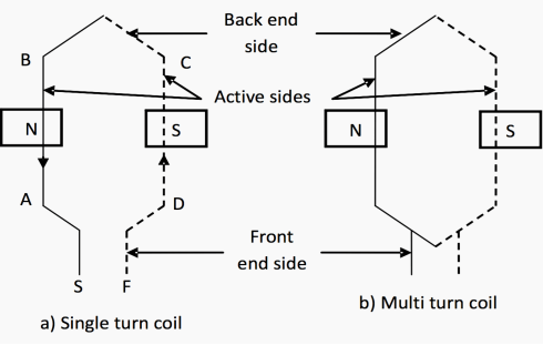
Fig 5: Single and Multi turn coil
Winding Coil representation
Figure 1.3(a) – Winding Coil representation
Generally, the total number of conductors per coil:
ZC = 2T
and, the total number of conductors for a given machine:
Z = ZCC
Where:
ZC = total number of conductors per coil
C = number of coils
Z = total number of conductors
T = number of turns per coil
Figure 5. Represents multi turn coil.
1. Active side of a coil
1. It is the part of a coil which lies in the slots under a magnetic pole and EMF is induced in this part only.
2. In Figure, coil sides AB and CD are called as active sides. For a double layer winding, one half portion of the coil drawn with solid line corresponds to the coil side lying on the top of a slot, and the dotted line corresponds to the coil side lying in the bottom layer of another slot.
2. Inactive side of a coil
1. The inactive side of a coil consists of two portions, namely the front end side and the back end side. In Figure 5, the portion of the conductor which joins the two active sides and placed around the core, is called the back end side of the coil.
2. The portions which are used to connect other coils are called front end side. These ends have two leads called as starting end S and finishing end F of a coil.
The overhang is defined as the configuration that the rotor length is longer than the stator length in the axial direction in this paper. In general, the overhang structure is used to enhance air-gap flux and improve power density while utilizing free space caused by the stator end winding
Key Takeaways:
1. A two turn coil has four conductors and a three turn coil has 6 conductors.
2. for a double layer winding, one half portion of the coil drawn with solid line.
3. The inactive side of a coil consists of two portions, namely the front end side and the back end side.
4. The overhang structure is used to enhance air-gap flux and improve power density
1. Coil pitch or coil span is defined as the angular distance between the two coil sides of one coil. It is expressed in terms of electrical space degree. Coil pitch is 180 electrical space degree for full pitch coil and less than 180 degree for short pitch coil.
2. When the angular distance between the two coil sides is one pole pitch, it is called full pitch coil. This means that both the coil sides are lying under the pole in full pitch coil. Figure below shows a full pitch coil.
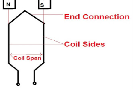
Fig 6 :Full pitched coils
3. The electrical space angle between the active coil length or coil side is equal to one pole pitch. Since 1 pole pitch is the angular distance between the two consecutive poles which is equal to 180 electrical degree, therefore the coil span for full pitch coil is also equal to 180 electrical degree.
Key Takeaways:
1. Coil pitch is 180 electrical space degree for full pitch coil and less than 180 degree for short pitch coil.
2. The electrical space angle between the active coil length or coil side is equal to one pole pitch
1. A winding is called concentrated winding when the number of slots per pole per phase is fractional and strictly lower than 1.
2. Concentrated type of winding can be done when the total number of poles in the armature is equal to the number of slots of the armature coil. Look at the image, the winding the total coils is wound in the single slots.
3. All the turns of this type of winding have the same magnetic axis, for example, the transformer winding. This type of winding gives maximum output voltage but not exact sinusoidal because it is independent of pitch and distribution factor.
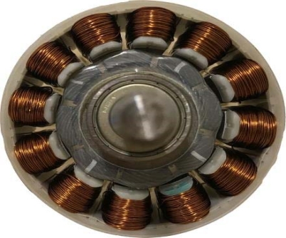
Fig 7 : concentrated winding
Key Takeaways:
1. The winding the total coils is wound in the single slots.
2. This type of winding gives maximum output voltage but not exact sinusoidal because it is independent of pitch and distribution factor.
1 Distributed winding is distributed along the air gap. In this winding poles are not equal to the number of slots. It does not have the same magnetic axis.
2 .The emf induced in the distributed winding is less due to the presence of pitch factor and distribution factor.
3. Distributed windings are used in DC machine, synchronous machine and induction machine.
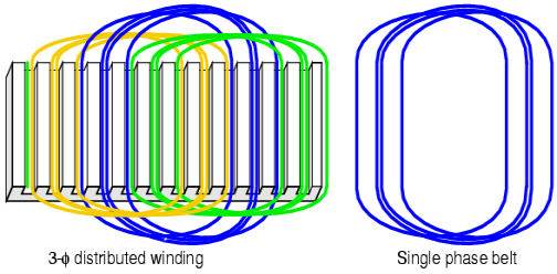
Fig 8 : Distributed winding
1.8.1 Advantages of Distributed Winding:
1 .It reduces harmonics present in the generated emf which also improves the sine waveform.
2. It reduces armature reaction and improves cooling.
3. The coil is distributed over the slots, so the core (copper and iron) is fully used.
4. It improves the mechanical strength of the winding.
Key Takeaways:
1. In these winding poles are not equal to the number of slots
2. In Distributed coil the coil is distributed over the slots, so the core (copper and iron) is fully used.
1. The term ‘winding axis’ is used in filament winding, which is a technique used in making a range of products like oars, bicycle forks, pipes, golf clubs, power and transmission poles etc.
2. Filament winding is a fabrication method used in the manufacture of open or closed end cylindrical structures, such as pressure vessels, water tanks and several other appliances. It involves winding filaments under a specified tension, over a rotating shaft or spindle, usually in a lathe.
Key takeaways:
1. In winding axis it involves winding filaments under a specified tension, over a rotating shaft or spindle, usually in a lathe.
1.10.1 3D visualisation for concentrated winding
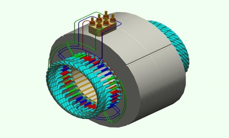
Fig 9 Concentrated winding 3D
1.10.2 3D Visualisation for distributed winding
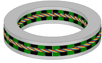
Fig 10: distributed winding 3D
1.11.1 MMF space wave of a concentrated coil
1. A cylindrical rotor with small air gap as shown in the figure below is assumed here. The stator is imagined to wound for two poles with a single N turn full pitch coil carrying current I in the direction indicated.
2. Each flux line radially crosses the air gap twice, Normal to the stator and rotor iron surfaces and it’s associated with constant mmf Ni. On the assumption that the reluctance of the iron path is negligible, half the mmf .
3. 2Ni is consumed to create flux from the rotor to stator in the air gap and the other half is used to establish flux from the stator to rotor in the air gap.
4. MMF and flux radially outwards from the rotor to the stator will be assumed to be positive and that from the stator to rotor is negative.
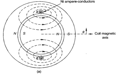
Fig 11: MMF of concentrated coil
1.11.2 MMF space wave of one distributed winding
1. Consider now a basic 2 pole structure with a round rotor, with 5 slots/pole/phase (SPP) and a 2 layer winding
2. The corresponding along with the mmf diagram which is now a stepped wave –obviously closer to the sine wave than the rectangular mmf wave of a single concentrated coil.
3. Here the SPP is odd , half the ampere conductors of the middle slot of the phase a and a ’contribute towards establishment of South Pole and half towards North Pole on the stator.
4. At each slot the mmf wave has a step jump of 2Nc Ic ampere conductors Where Nc Is the coil turns and IcIs the conductor current.


Where Ia = phase current =A Ic
It now follow that,
AT/ pole/ phase = 
F Ip (concentred winding) =
F Ip (distributed winding) =


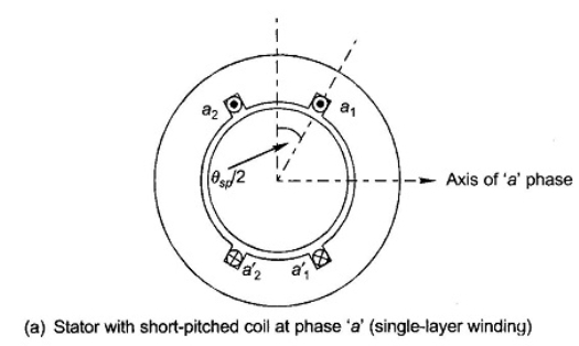
Fig 12 : MMF of distributed coil
Key Takeaways:
1. Each flux line radially crosses the air gap twice
2. The reluctance of the iron path is negligible, half the mmf .
3. The SPP is odd , half the ampere conductors of the middle slot of the phase a
1. A sinusoidally distributed winding is excited with a sinusoidal current. The resulting pulsating radial flux density distribution is shown plotted along a circular path in the air gap (which is greatly enlarged for visual purposes.
2. When the windings are excited with balanced 3-phase sinusoidal currents, the combined effect is equivalent to having a single sinusoidally distributed winding excited with a constant current and rotating at the stator frequency.
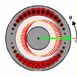
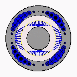
Fig 13: Sinusoidally distributed winding
Key takeaways:
1. A sinusoidally distributed winding is excited with a sinusoidal current
2. The resulting pulsating radial flux density distribution is greatly enlarged for visual purposes.
1. If all the coil sides of any one phase under one pole are bunched in one slot, the winding obtained is known as concentrated winding and the total emf induced is equal to the arithmetic sum of the emfs induced in all the coils of one phase under one pole.
2. But in practical cases, for obtaining smooth sinusoidal voltage waveform, armature winding of alternator is not concentrated but distributed among the different slots to form polar groups under each pole. In distributed winding, coil sides per phase are displaced from each other by an angle equal to the angular displacement of the adjacent slots. Hence, the induced emf per coil side is not an angle equal to the angular displacement of the slots.
3. So, the resultant emf of the winding is the phasor sum of the induced emf per coil side. As it is phasor sum, must be less than the arithmetic sum of these induced emfs.
4. Resultant emf would be an arithmetic sum if the winding would have been a concentrated one.
5. As per definition, distribution factor is a measure of resultant emf of a distributed winding in compared to a concentrated winding.
6. We express it as the ratio of the phasor sum of the emfs induced in all the coils distributed in some slots under one pole to the arithmetic sum of the emfs induced
Key Takeaways:
1. For obtaining smooth sinusoidal voltage waveform, armature winding of alternator is not concentrated but distributed among the different slots to form polar groups under each pole.
2. Resultant emf would be an arithmetic sum if the winding would have been a concentrated one
1. Winding factor is a technique that is employed to improve the rms generated voltage or electromotive force (EMF) in a three-phase AC electrical machine so that the output voltage and hence torque does not have any harmonics in it which may reduce efficiency.
2. This is because the armature winding of each phase is distributed in a number of slots. Since the EMF induced in different slots are not in phase, their phasor sum is less than their numerical sum.
3. This reduction factor is called distribution factor Kd. Another factor that can reduce the winding factor is when the slot pitch is smaller than the pole pitch, called pitch factor Kp.
The winding factor can be calculated as
Kw = Kd * Kp
4. Example:
For a 3-phase 6 slot 4 pole non-overlapping winding motor:
Coil pitch=2π/6 = and 2π/3 (Elec)g Pole pitch =2π/ 4= π (Elec)
Most of 3phase motors have winding factor values between 0.85 and 0.95.
Key Takeaways:
1. Winding factor is a technique that is employed to improve the rms generated voltage
2. Their phasor sum is less than their numerical sum.
3. This reduction factor is called distribution factor Kd.
References
1. A. E. Fitzgerald and C. Kingsley, "Electric Machinery”, McGraw Hill Education,2013.
2. M. G. Say, “Performance and design of AC machines”, CBS Publishers,2002.
3. P. S. Bimbhra, “Electrical Machinery”, Khanna Publishers,2011.
4. I. J. Nagrath and D. P. Kothari, “Electric Machines”, McGraw Hill Education,2010.
5. A. S. Langsdorf, “Alternating current machines”, McGraw Hill Education,1984.
6. P. C. Sen, “Principles of Electric Machines and Power Electronics”, John Wiley & Sons,2007.
UNIT 1
FUNDAMENTALS OF AC MACHINE WINDINGS
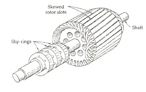
Fig 1: Induction motor (outer winding)
A three phase Induction motor mainly consists of two parts called as the Stator and the Rotor. The stator is the stationary part of the induction motor, and the rotor is the rotating part. The construction of the stator is similar to the three-phase synchronous motor, and the construction of rotor is different for the different machine.
1.1.2 Construction of Stator
The stator is built up of high-grade alloy steel laminations to reduce eddy current losses. It has three main parts, namely outer frame, the stator core and a stator winding.
1.1.3 Outer frame
It is the outer body of the motor. Its main function is to support the stator core and to protect the inner parts of the machine. For small machines, the outer frame is casted, but for the large machine, it is fabricated. The figure below shows the stator construction.
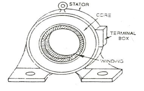
Fig 2: Induction motor inner winding
The stator core is built of high-grade silicon steel stampings. Its main function is to carry the alternating magnetic field which produces hysteresis and eddy current losses. The stampings are fixed to the stator frame. Each stamping are insulated from the other with a thin varnish layer. The thickness of the stamping usually varies from 0.3 to 0.5 mm. Slots are punched on the inner side of the stampings.
Construction of an induction motor
1.1.5 Stator windings
1. The core of the stator carries three phase windings which are usually supplied from a three-phase supply system.
2. The six terminals of the windings (two of each phase) are connected in the terminal box of the machine.
3. The stator of the motor is wound for a definite number of poles, depending on the speed of the motor.
4. If the number of poles is greater, the speed of the motor will be less and if the number of poles is less than the speed will be high.
1.1.6 Physical arrangement of windings in stator are-
Pre-manufactured coils can be inserted into the stator slots one by one to form a three-phase distributed winding
All the windings are in a single-speed three-phase motor design.
Key Takeaways:
1. The construction of the stator is similar to the three-phase synchronous motor
2. The stator is built up of high-grade alloy steel laminations to reduce eddy current losses.
3. For small machines, the outer frame is casted, but for the large machine, it is fabricated
4. The stator core is built of high-grade silicon steel stampings.
5. If the number of poles is greater, the speed of the motor will be less
6. All the windings are in a single-speed
1.2.1 What is cylindrical rotor? (Motor)
1. It is the moving part in an electromagnetic system of the motor, generator and an alternator. It is also called as the Flywheel, rotating magnetic core, an alternator. In an alternator, it includes permanent magnets that move approximately to the iron plates of the stator to produce an AC (Alternating Current).
2. It uses existing motion for its function. The rotation of this can be occurred because of the interaction between magnetic fields & the windings which generate torque in the region of the axis.
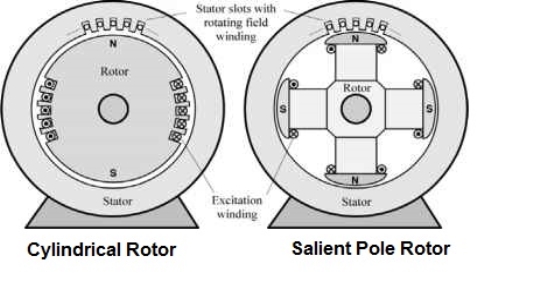
Fig 3: Cylindrical and Salient pole rotor
1.2.2 Construction and Working Principle of a Rotor
1. In a three-phase induction motor, once an AC is applied to the rotor then the windings of stator strengthen to generate a rotary magnetic flux. The flux generates a magnetic field in the air gap among the stator & the rotor to induce a voltage for generating the current throughout the bars. The circuit of this can be shorted & the flow of current will be in the conductors.
2. The act of the rotary flux & the current generates a force to generate a torque to begin the motor. The rotor in an alternator can be designed with a wire coil enclosed in the region of an iron core.
3. The magnetic component of this can be made with the laminations of the steel to assist stamping conductor slot to exact sizes & shapes. Whenever the current travels in the coil in a magnetic field then it creates a field current in the region of the core.
4. The strength of the field current mainly controls the level of power in the magnetic field. DC (direct current) drives the field current in the direction of the wire coil through a set of slip rings & brushes.
5. Similar to any magnet, the magnetic field generated will include two poles like south & north. The direction of the motor in the clockwise can be controlled through the magnets & magnetic fields fixed in this design, which allows the motor to run in a counter clockwise direction.
1.2.3 Physical arrangement of windings in cylindrical rotor are-
1. The windings for rotor are less complex than stator.
2. The windings of a rotor are less insulated.
3. The size of the cylindrical rotor winding is small as it does not need to transmit huge current through it.
Key Takeaways:
1. It includes permanent magnets that move approximately to the iron plates of the stator to produce an AC.
2. The strength of the field current mainly controls the level of power in the magnetic field
3. The rotor in an alternator can be designed with a wire coil enclosed in the region of an iron core
4. The size of the cylindrical rotor winding is small as it does not need to transmit huge current through it.
1. Because stators are cylindrical, the slots are shaped like wedges. The number of slots depends on how many phases of power are provided to the coil windings.
2. A basic single-phase motor usually has four slots that contain two pairs of coil windings, each offset by 90 degrees; a basic three-phase motor has six slots with three pairs of coil windings, each pair offset by 120 degrees.
3. To complicate matters, multiples of pole pairs can be utilized to increase the corresponding number of slots.
4. Some of the greatest challenges for a custom stator manufacturer are related to maximizing the amount of copper wire inserted into each slot (commonly referred to as “slot fill”) to maximize torque output.
5. Stator manufacturing is based on relatively simple principles but stators are inherently difficult to build.
6. Beyond the physical design limits and the question of how much slot fill is appropriate for the application, engineers have to account for manufacturability.
7. To balance these requirements, engineers must rely on proven design practices and custom manufacturing techniques.
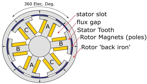
Fig 4: Slots of diagram
Key Takeaways:
1. Multiples of pole pairs can be utilized to increase the corresponding number of slots.
2. Stator manufacturing is based on relatively simple principles but stators are inherently difficult to build.
3. The number of slots depends on how many phases of power are provided to the coil windings.
A single turn/coil has two active sides, or otherwise called as conductors. Similarly, a two turn coil has four conductors and a three turn coil has 6 conductors.
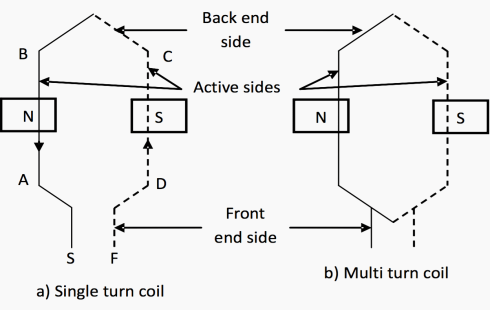
Fig 5: Single and Multi turn coil
Winding Coil representation
Figure 1.3(a) – Winding Coil representation
Generally, the total number of conductors per coil:
ZC = 2T
and, the total number of conductors for a given machine:
Z = ZCC
Where:
ZC = total number of conductors per coil
C = number of coils
Z = total number of conductors
T = number of turns per coil
Figure 5. Represents multi turn coil.
1. Active side of a coil
1. It is the part of a coil which lies in the slots under a magnetic pole and EMF is induced in this part only.
2. In Figure, coil sides AB and CD are called as active sides. For a double layer winding, one half portion of the coil drawn with solid line corresponds to the coil side lying on the top of a slot, and the dotted line corresponds to the coil side lying in the bottom layer of another slot.
2. Inactive side of a coil
1. The inactive side of a coil consists of two portions, namely the front end side and the back end side. In Figure 5, the portion of the conductor which joins the two active sides and placed around the core, is called the back end side of the coil.
2. The portions which are used to connect other coils are called front end side. These ends have two leads called as starting end S and finishing end F of a coil.
The overhang is defined as the configuration that the rotor length is longer than the stator length in the axial direction in this paper. In general, the overhang structure is used to enhance air-gap flux and improve power density while utilizing free space caused by the stator end winding
Key Takeaways:
1. A two turn coil has four conductors and a three turn coil has 6 conductors.
2. for a double layer winding, one half portion of the coil drawn with solid line.
3. The inactive side of a coil consists of two portions, namely the front end side and the back end side.
4. The overhang structure is used to enhance air-gap flux and improve power density
1. Coil pitch or coil span is defined as the angular distance between the two coil sides of one coil. It is expressed in terms of electrical space degree. Coil pitch is 180 electrical space degree for full pitch coil and less than 180 degree for short pitch coil.
2. When the angular distance between the two coil sides is one pole pitch, it is called full pitch coil. This means that both the coil sides are lying under the pole in full pitch coil. Figure below shows a full pitch coil.
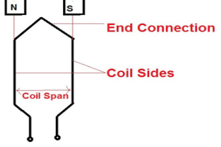
Fig 6 :Full pitched coils
3. The electrical space angle between the active coil length or coil side is equal to one pole pitch. Since 1 pole pitch is the angular distance between the two consecutive poles which is equal to 180 electrical degree, therefore the coil span for full pitch coil is also equal to 180 electrical degree.
Key Takeaways:
1. Coil pitch is 180 electrical space degree for full pitch coil and less than 180 degree for short pitch coil.
2. The electrical space angle between the active coil length or coil side is equal to one pole pitch
1. A winding is called concentrated winding when the number of slots per pole per phase is fractional and strictly lower than 1.
2. Concentrated type of winding can be done when the total number of poles in the armature is equal to the number of slots of the armature coil. Look at the image, the winding the total coils is wound in the single slots.
3. All the turns of this type of winding have the same magnetic axis, for example, the transformer winding. This type of winding gives maximum output voltage but not exact sinusoidal because it is independent of pitch and distribution factor.
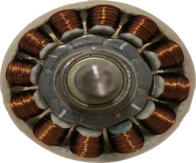
Fig 7 : concentrated winding
Key Takeaways:
1. The winding the total coils is wound in the single slots.
2. This type of winding gives maximum output voltage but not exact sinusoidal because it is independent of pitch and distribution factor.
1 Distributed winding is distributed along the air gap. In this winding poles are not equal to the number of slots. It does not have the same magnetic axis.
2 .The emf induced in the distributed winding is less due to the presence of pitch factor and distribution factor.
3. Distributed windings are used in DC machine, synchronous machine and induction machine.
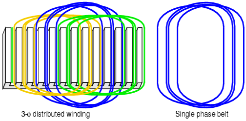
Fig 8 : Distributed winding
1.8.1 Advantages of Distributed Winding:
1 .It reduces harmonics present in the generated emf which also improves the sine waveform.
2. It reduces armature reaction and improves cooling.
3. The coil is distributed over the slots, so the core (copper and iron) is fully used.
4. It improves the mechanical strength of the winding.
Key Takeaways:
1. In these winding poles are not equal to the number of slots
2. In Distributed coil the coil is distributed over the slots, so the core (copper and iron) is fully used.
1. The term ‘winding axis’ is used in filament winding, which is a technique used in making a range of products like oars, bicycle forks, pipes, golf clubs, power and transmission poles etc.
2. Filament winding is a fabrication method used in the manufacture of open or closed end cylindrical structures, such as pressure vessels, water tanks and several other appliances. It involves winding filaments under a specified tension, over a rotating shaft or spindle, usually in a lathe.
Key takeaways:
1. In winding axis it involves winding filaments under a specified tension, over a rotating shaft or spindle, usually in a lathe.
1.10.1 3D visualisation for concentrated winding
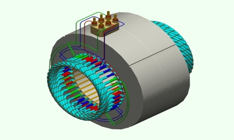
Fig 9 Concentrated winding 3D
1.10.2 3D Visualisation for distributed winding
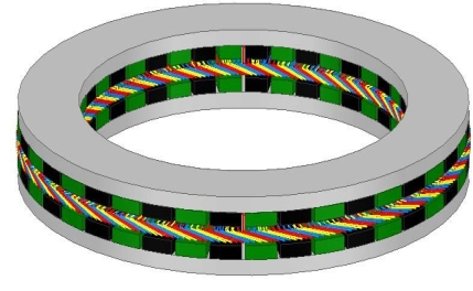
Fig 10: distributed winding 3D
1.11.1 MMF space wave of a concentrated coil
1. A cylindrical rotor with small air gap as shown in the figure below is assumed here. The stator is imagined to wound for two poles with a single N turn full pitch coil carrying current I in the direction indicated.
2. Each flux line radially crosses the air gap twice, Normal to the stator and rotor iron surfaces and it’s associated with constant mmf Ni. On the assumption that the reluctance of the iron path is negligible, half the mmf .
3. 2Ni is consumed to create flux from the rotor to stator in the air gap and the other half is used to establish flux from the stator to rotor in the air gap.
4. MMF and flux radially outwards from the rotor to the stator will be assumed to be positive and that from the stator to rotor is negative.
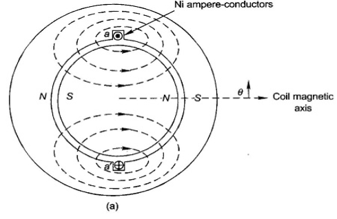
Fig 11: MMF of concentrated coil
1.11.2 MMF space wave of one distributed winding
1. Consider now a basic 2 pole structure with a round rotor, with 5 slots/pole/phase (SPP) and a 2 layer winding
2. The corresponding along with the mmf diagram which is now a stepped wave –obviously closer to the sine wave than the rectangular mmf wave of a single concentrated coil.
3. Here the SPP is odd , half the ampere conductors of the middle slot of the phase a and a ’contribute towards establishment of South Pole and half towards North Pole on the stator.
4. At each slot the mmf wave has a step jump of 2Nc Ic ampere conductors Where Nc Is the coil turns and IcIs the conductor current.


Where Ia = phase current =A Ic
It now follow that,
AT/ pole/ phase = 
F Ip (concentred winding) =
F Ip (distributed winding) =


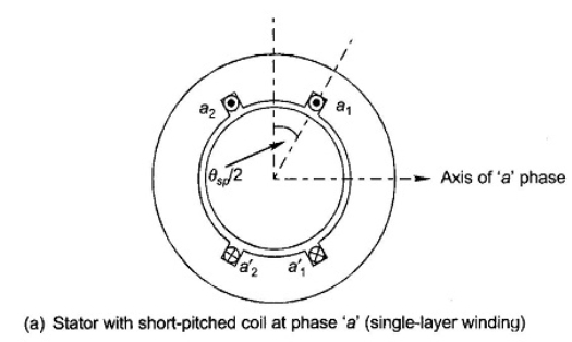
Fig 12 : MMF of distributed coil
Key Takeaways:
1. Each flux line radially crosses the air gap twice
2. The reluctance of the iron path is negligible, half the mmf .
3. The SPP is odd , half the ampere conductors of the middle slot of the phase a
1. A sinusoidally distributed winding is excited with a sinusoidal current. The resulting pulsating radial flux density distribution is shown plotted along a circular path in the air gap (which is greatly enlarged for visual purposes.
2. When the windings are excited with balanced 3-phase sinusoidal currents, the combined effect is equivalent to having a single sinusoidally distributed winding excited with a constant current and rotating at the stator frequency.
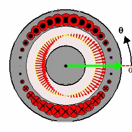
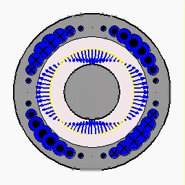
Fig 13: Sinusoidally distributed winding
Key takeaways:
1. A sinusoidally distributed winding is excited with a sinusoidal current
2. The resulting pulsating radial flux density distribution is greatly enlarged for visual purposes.
1. If all the coil sides of any one phase under one pole are bunched in one slot, the winding obtained is known as concentrated winding and the total emf induced is equal to the arithmetic sum of the emfs induced in all the coils of one phase under one pole.
2. But in practical cases, for obtaining smooth sinusoidal voltage waveform, armature winding of alternator is not concentrated but distributed among the different slots to form polar groups under each pole. In distributed winding, coil sides per phase are displaced from each other by an angle equal to the angular displacement of the adjacent slots. Hence, the induced emf per coil side is not an angle equal to the angular displacement of the slots.
3. So, the resultant emf of the winding is the phasor sum of the induced emf per coil side. As it is phasor sum, must be less than the arithmetic sum of these induced emfs.
4. Resultant emf would be an arithmetic sum if the winding would have been a concentrated one.
5. As per definition, distribution factor is a measure of resultant emf of a distributed winding in compared to a concentrated winding.
6. We express it as the ratio of the phasor sum of the emfs induced in all the coils distributed in some slots under one pole to the arithmetic sum of the emfs induced
Key Takeaways:
1. For obtaining smooth sinusoidal voltage waveform, armature winding of alternator is not concentrated but distributed among the different slots to form polar groups under each pole.
2. Resultant emf would be an arithmetic sum if the winding would have been a concentrated one
1. Winding factor is a technique that is employed to improve the rms generated voltage or electromotive force (EMF) in a three-phase AC electrical machine so that the output voltage and hence torque does not have any harmonics in it which may reduce efficiency.
2. This is because the armature winding of each phase is distributed in a number of slots. Since the EMF induced in different slots are not in phase, their phasor sum is less than their numerical sum.
3. This reduction factor is called distribution factor Kd. Another factor that can reduce the winding factor is when the slot pitch is smaller than the pole pitch, called pitch factor Kp.
The winding factor can be calculated as
Kw = Kd * Kp
4. Example:
For a 3-phase 6 slot 4 pole non-overlapping winding motor:
Coil pitch=2π/6 = and 2π/3 (Elec)g Pole pitch =2π/ 4= π (Elec)
Most of 3phase motors have winding factor values between 0.85 and 0.95.
Key Takeaways:
1. Winding factor is a technique that is employed to improve the rms generated voltage
2. Their phasor sum is less than their numerical sum.
3. This reduction factor is called distribution factor Kd.
References
1. A. E. Fitzgerald and C. Kingsley, "Electric Machinery”, McGraw Hill Education,2013.
2. M. G. Say, “Performance and design of AC machines”, CBS Publishers,2002.
3. P. S. Bimbhra, “Electrical Machinery”, Khanna Publishers,2011.
4. I. J. Nagrath and D. P. Kothari, “Electric Machines”, McGraw Hill Education,2010.
5. A. S. Langsdorf, “Alternating current machines”, McGraw Hill Education,1984.
6. P. C. Sen, “Principles of Electric Machines and Power Electronics”, John Wiley & Sons,2007.