UNIT 1
DSP
An audio system is required to operate in an entire audible range of frequencies, which may be beyond the capability of any single speaker driver. Several drivers, such as the speaker cones and horns, each covering a different frequency range, are used to cover the full audio frequency range.
The woofer response to low frequencies, while the Twitter responds to high frequencies. The incoming digital audio signal is split into two bands by using a digital low pass filter and digital high pass filter in parallel. Then the separated audio signals are amplified. Finally, they are sent to their corresponding speaker drivers.
Although the traditional crossover systems are designed using the analogue circuits, the digital crossover system offers a cost-effective solution with programmability, flexibility, and high quality.

To perform the processing digitally, there is a need for an interface between the analog signal and the digital processor. This interface is called an analog-to-digital (A/D) converter. The output of the A? D converter is a digital signal that is appropriate as an input to the digital processor.
The digital signal processor may be a large programmable digital computer or a small microprocessor programmed to perform the desired operations on the input signal. It may also be a hardwired digital processor configured to perform a specified set of operations on the input signal.
Programmable machines provide the flexibility to change the signal processing operations through a change in the software, whereas hardwired machines are difficult to reconfigure. Consequently, programmable signal processors are in very common use.
On the other hand, when signal processing operations are well defined, a hardwired implementation of the operations can be optimized, resulting in a cheaper signal processor and, usually, one that runs faster than its programmable counterpart.
In applications where the digital output from the digital signal processor is to be given to the user in analog form, such as in speech communications, we must provide another interface from the digital domain to analog domain. Such an interface is called a digital-to-analog (D/A) converter. Thus the signal is provided to the user in analog form.
However, there are other practical applications involving signal analysis, where the desired information is conveyed in digital form and no D/A converter is required. For example, in the digital processing of radar signals, the information extracted from the radar signal, such as the position of the aircraft and its speed, may simply be printed on paper. There is no need for a D/A converter in this case.
1. Physical size of analog systems is quite large while digital processors are more compact and lighter in weight.
2. Analog systems are less accurate because of component tolerance ex R, L, C and active components. Digital components are less sensitive to the environmental changes, noise and disturbances.
3. Digital system is most flexible as software programs & control programs can be easily modified.
4. Digital signal can be stores on digital hard disk, floppy disk or magnetic tapes. Hence becomes transportable. Thus easy and lasting storage capacity.
5. Digital processing can be done offline.
6. Mathematical signal processing algorithm can be routinely implemented on digital signal processing systems. Digital controllers are capable of performing complex computation with constant accuracy at high speed.
7. Digital signal processing systems are upgradeable since that are software controlled.
8. Possibility of sharing DSP processor between several tasks.
9. The cost of microprocessors, controllers and DSP processors are continuously going down. For some complex control functions, it is not practically feasible to construct analog controllers.
10. Single chip microprocessors, controllers and DSP processors are more versatile and powerful.
Signals are classified into the following categories:
- Continuous Time and Discrete Time Signals
- Deterministic and Non-deterministic Signals
- Even and Odd Signals
- Periodic and Aperiodic Signals
- Energy and Power Signals
- Real and Imaginary Signals
Continuous Time and Discrete Time Signals
A signal is said to be continuous when it is defined for all instants of time.

A signal is said to be discrete when it is defined at only discrete instants of time/

Deterministic and Non-deterministic Signals
A signal is said to be deterministic if there is no uncertainty with respect to its value at any instant of time. Or, signals which can be defined exactly by a mathematical formula are known as deterministic signals.

A signal is said to be non-deterministic if there is uncertainty with respect to its value at some instant of time. Non-deterministic signals are random in nature hence they are called random signals. Random signals cannot be described by a mathematical equation. They are modelled in probabilistic terms.

Even and Odd Signals
A signal is said to be even when it satisfies the condition x(t) = x(-t)
Example 1: t2, t4… cost etc.
Let x(t) = t2
x(-t) = (-t)2 = t2 = x(t)
∴,∴, t2 is even function
2: As shown in the following diagram, rectangle function x(t) = x(-t) so it is also even function.

A signal is said to be odd when it satisfies the condition x(t) = -x(-t)
Example: t, t3 ... And sin t
Let x(t) = sin t
x(-t) = sin(-t) = -sin t = -x(t)
∴,∴, sin t is odd function.
Any function ƒ(t) can be expressed as the sum of its even function ƒe(t) and odd function ƒo(t).
ƒ(t ) = ƒe(t ) + ƒ0(t )
Where
ƒe(t ) = ½[ƒ(t ) +ƒ(-t )]
Periodic and Aperiodic Signals
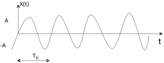
A signal is said to be periodic if it satisfies the condition x(t) = x(t + T) or x(n) = x(n + N).
Where
T = fundamental time period,
1/T = f = fundamental frequency.

The above signal will repeat for every time interval T0 hence it is periodic with period T0.
Energy and Power Signals
A signal is said to be energy signal when it has finite energy.

A signal is said to be power signal when it has finite power.

NOTE: A signal cannot be both, energy and power simultaneously. Also, a signal may be neither energy nor power signal.
Power of energy signal = 0
Energy of power signal = ∞
Real and Imaginary Signals
A signal is said to be real when it satisfies the condition x(t) = x*(t)
A signal is said to be odd when it satisfies the condition x(t) = -x*(t)
Example:
If x(t)= 3 then x*(t)=3*=3 here x(t) is a real signal.
If x(t)= 3j then x*(t)=3j* = -3j = -x(t) hence x(t) is a odd signal.
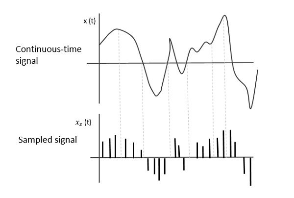
The following figure indicates a continuous-time signal x (t) and a sampled signal xs (t). When x (t) is multiplied by a periodic impulse train, the sampled signal xs (t) is obtained.

Sampling Rate
To discretize the signals, the gap between the samples should be fixed. That gap can be termed as a sampling period Ts.
Sampling Frequency=1/Ts=fs
Where,
- Ts is the sampling time
- Fs is the sampling frequency or the sampling rate
Sampling frequency is the reciprocal of the sampling period. This sampling frequency, can be simply called as Sampling rate. The sampling rate denotes the number of samples taken per second, or for a finite set of values.
Nyquist Rate
Suppose that a signal is band-limited with no frequency components higher than W Hertz. That means, W is the highest frequency. For such a signal, for effective reproduction of the original signal, the sampling rate should be twice the highest frequency.
Which means,
fS=2W
Where,
- fS is the sampling rate
- W is the highest frequency
This rate of sampling is called as Nyquist rate.
Signals are represented mathematically as functions of one or more independent variables. Here we focus attention on signals involving a single independent variable. For convenience, this will generally refer to the independent variable as time.
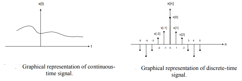
There are two types of signals: continuous-time signals and discrete-time signals.
Continuous-time signal: the variable of time is continuous. A speech signal as a function of time is a continuous-time signal.
Discrete-time signal: the variable of time is discrete. The weekly Dow Jones stock market index is an example of discrete-time signal.
