Module 1
Fundamentals of Microprocessors
The microprocessor is one component of the microcomputer.
A microcomputer is a computer similar to any other computer, except that the CPU functions of the microcomputer are performed by the microprocessor. The term peripheral is used for input/ output devices.
The various components of the microcomputer are :
The MPU (microprocessor unit) is the heart of every microcomputer. It performs which are:
1. Providing timing and control signals for all elements of the µC
2. Fetching instructions and data from memory
3. Transferring data to and from memory and I/O devices
4. Decoding instructions
5. Performing arithmetic and logic operations called for by instructions
6. Responding to I/O generated control signals such as RESET and INTERRUPT. The MPU contains all of the logic circuitry for performing these functions, but its internal logic is generally not externally accessible.
8-bit Microprocessor

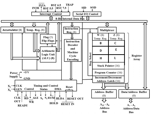
Figure: 8085 microprocessor architecture.
The architecture of microprocessor 8085 can be divided into seven parts as follows:
Register Unit:
● 8085 has six general purpose data registers to store 8-bit data.
● These registers are named as B, C, D, E, H and L as shown in figure
● The user can use these registers to store or copy a data temporarily during the execution of a program by using data transfer instructions.
● These registers are of 8 bits but whenever the microprocessor has to handle 16-bit data, these registers can be combined as register pairs – BC, DE and HL.
● There are two internal registers – W and X. These registers are only for internal operation like execution of CALL and XCHG instructions and not available to the user.
Program Counter (PC)
● a 16-bit register deals with sequencing the execution of instructions.
● This register is a memory pointer.
● Memory locations have 16-bit addresses which are why this is a 16-bit register.
● The microprocessor uses this register to sequence the execution of the instructions.
● The function of the program counter is to point to the memory address from which the next byte is to be fetched.
● When a byte (machine code) is being fetched, the program counter is incremented by one to point to the next memory location.
Stack Pointer (SP)
● SP is also a 16-bit register used as a memory pointer.
● It points to a memory location in R/W memory, called the stack.
● The beginning of the stack is defined by loading a 16-bit address in the stack pointer.
MUX/DEMUX unit:
● This unit is used to select a register out of all the available registers.
● This unit behaves as a MUX when data is going from the register to the internal data bus.
● It behaves as a DEMUX when data is coming to a register from the internal data bus of the microprocessor.
● The register select will behave as the function selection lines of the MUX/DEMUX.
Address Buffer Register & Data/Address Buffer Register
● These registers hold the address/data, received from PC/internal data bus and then load the external address and data buses.
● These registers actually behave as the buffer stage between the microprocessor and external system buses
Control Unit:
● The control unit generates signals within the microprocessor to carry out the instruction, which has been decoded.
● In reality it causes connections between blocks of the microprocessor to be opened or closed, so that the data goes where it is required and the ALU operations occur.
● The control unit itself consists of three parts; the instruction registers (IR), instruction decoder and machine cycle encoder and timing and control unit.
Instruction Register
● This register holds the machine code of the instruction.
● When a microprocessor executes a program it reads the opcode from the memory, this opcode is stored in the instruction register.
Instruction Decoder & Machine Cycle Encoder
● The IR sends the machine code to this unit.
● This unit, as its name suggests, decodes the opcode and finds out what is to be done in response to the coming opcode and how many machine cycles are required to execute this instruction.
Timing & Control unit:
● The control unit generates signals within the microprocessor to carry out the instruction, which has been decoded.
● In reality, it causes certain connections between blocks of the microprocessor to be opened or closed, so that the data goes where it is required and the ALU operations occur.
Arithmetic & Logical Unit:
● The ALU performs the actual numerical and logical operation such as ‘add’, ‘subtract’, ‘AND’, ‘OR’, etc.
● ALU uses data from memory and from the accumulator to perform the arithmetic operations and always stores the result of the operation in the accumulator.
● ALU consists of an accumulator, flag register and temporary register.
Accumulator
● The accumulator is an 8-bit register that is a part of ALU.
● This register is used to store 8-bit data and perform arithmetical and logical operations.
● The result of an operation is stored in the accumulator.
● It is also identified as register A.
Flags register
● Flag register includes five flip-flops, which are set or reset after an operation according to the data conditions of the result in the accumulator and other registers.
● They are called zero (Z), carry (CY), sign (S), parity (P) and auxiliary carry (AC) flags; their bit positions in the flag register are shown in fig.
● The microprocessor uses these flags to set and test data conditions.
Interrupt Control Unit:
● The interrupt control unit has 5 interrupt inputs TRAP,RST 7.5, RST 6.5, RST 5.5 & INTR and one acknowledge signal INTA.
● It controls the interrupt activity of 8085 microprocessors.
Serial IO Control Unit:
● 8085 serial IO control provides two lines, SOD and SID for serial communication.
● The serial output data (SOD) line is used to send data serially and serial input data line (SID) is used to receive data serially.
8-bit Microcontroller Architecture

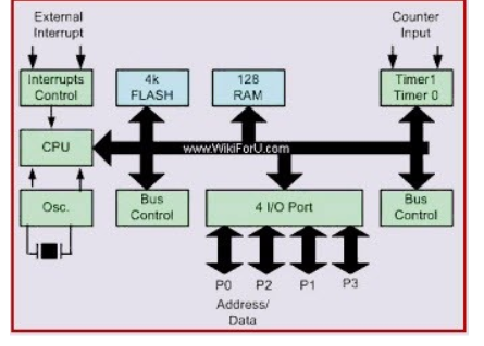
8051 Architecture
Central Processor Unit (CPU)
The brain of any processing device of the microcontroller is the CPU. It monitors and controls all operations performed on these units. It reads a program written in ROM memory, executes and does the expected task.
Interrupts
Interrupt is a subroutine call that interrupts the microcontroller's main operations or work and causes it to execute any other program, at the time of operation. It provides a mechanism to put on hold the ongoing operations, execute a subroutine and resume to another type of operation.
8051 has five interrupt sources:
INTO
● TFO
● INT1
● TF1
● R1/T1
(INT0) ̅ and (INT1) ̅ are external interrupts negative edge triggered or low level triggered. When these interrupts are activated, the corresponding flags are set except for serial interrupts.
When the processor branches to ISR the interrupt flags are cleared. The external interrupts are timer and serial port interrupts.
Memory
They require memory to save as well as read so that the microcontroller performs specific operations of the task.
The memory which is used to store the program is known as code memory or Program memory. It is also known as ROM memory.
8051 data memory is used to store data temporarily for operation known as RAM memory. It has 4K of code memory or program memory and 128 bytes of data memory of RAM.
BUS
A collection of wires that work as a communication channel or medium for transfer of data. It consists of 8, 16 or more wires of microcontroller. Thus, they carry 8 bits or 16 bits of data simultaneously. There are two types of buses which are
● Address Bus
● Data Bus
Address Bus:
Microcontroller 8051 has a 16-bit address bus for transferring data. It addresses memory locations to transfer addresses from CPU to Memory. It has four addressing modes that are:
● Immediate addressing modes.
● Bank address (or) Register addressing mode.
● Direct Addressing mode.
● Register indirect addressing mode.
Data Bus: Microcontroller 8051 has 8 bits of data bus used to carry data for applications.
Oscillator
The 8051 microcontroller has an on-chip oscillator that acts as a clock source for the CPU of the microcontroller. The output pulses of the oscillator are stable. Therefore, it enables synchronized work for all the parts of the Microcontroller system.
Input/Output Port
To control the operation of machines, microcontrollers are used in embedded systems. To connect to other machines, devices or peripherals I/O interfacing ports is required. Microcontroller 8051 has 4 input and output ports to connect to other peripherals
Timers/Counters
The 8051 microcontroller has two 16-bit timers and counters. The counters are again divided into 8-bit registers. Timers are used for measurement of time intervals to determine pulse width.
Most 8-bit processors are old architectures, so they tend to be slower. They are cheap. They also tend to have a low limit on supported RAM/other storage, but the actual amount depends on the family.
16-bit processors tend to focus on price as well, but there is a large range of parts available, some of which have fairly high performance and large amounts of on-chip peripherals. These parts usually perform faster than 8-bit parts on math where the precision is greater than 8 bits, and tend to have more addressable memory.
32-bit chips compete primarily on performance for an application. There is a considerable range of 32-bit parts available, each targeted at some specific application. They tend to come loaded with peripherals and compete on feature completeness. They have a large amount of addressable memory and the performance tends to be better than 16-bit parts.
An embedded system can be a computer hardware system having software embedded in it. An embedded system can be an independent system or it can be a part of a large system. An embedded system is a microcontroller or microprocessor based system designed to perform a specific task.
For example, let us consider the fire alarm as an embedded system. This system only senses smoke.
An embedded system consists of three components −
● It has hardware.
● It has application software.
● It has a Real Time Operating system (RTOS) which defines the way the system works. It sets the rules during the execution of the application program. A small scale embedded system may not have RTOS.
Characteristics of an Embedded System
● Single-functioned − An embedded system usually performs a specialized operation and does the same repeatedly. For example: A pager always functions as a pager.
● Tightly constrained − All computing systems have constraints on design metrics, but those on an embedded system can be especially tight. Design metrics is a measure of an implementation's features such as its cost, size, power, and performance
● Reactive and Real time − Many embedded systems must continually react to changes in the system's environment and must compute certain results in real time without any delay.
● Memory − It must have a memory, as its software usually embeds in ROM. It does not need any secondary memories in the computer.
● Connected − It must have connected peripherals to connect input and output devices.
● HW-SW systems − Software is used for more features and flexibility. Hardware is used for performance and security.

While developing an embedded system there is an option to base the computational hardware around a microcontroller which can be a microcontroller or microprocessor.
Both approaches have their attractions but typically the microcontroller, MCU, is found in applications where size, low power and low cost are key requirements.
The MCU microcontroller is different to a microprocessor where it contains more elements of the overall processing engine within the one chip.
Most of the processing engine components are brought onto a single chip which reduces size and cost. This enables it to become economically viable to digitally control where more devices and processes take place. Also, it is found that mixed signal microcontrollers are being increasingly used, integrating analogue components needed to control non-digital electronic systems.
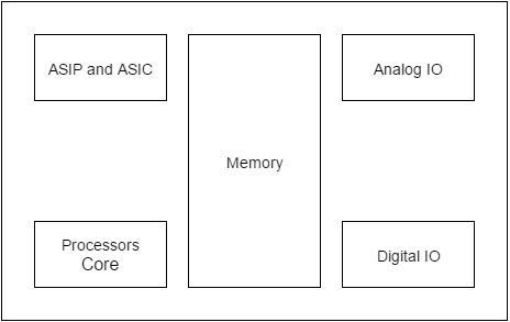
Microcontrollers comprise the main elements of a small computer system on a single chip. They contain the memory, and IO as well as the CPU one the same chip. This considerably reduces the size, making them ideal for small embedded systems.
Also microcontrollers are often intended for low power and low processing applications where some microcontrollers use 4 bit words and they may also operate with very low clock rates - some 10 kHz and less to conserve power. This means that some MCUs consume a milliwatt or so and they may also have sleep consumption levels of a few nanowatts.
There are two other members in the 8051 family of microcontrollers. They are the 8052 and the 8031.
8052 microcontrollers
The 8052 is another member of the 8051 family. The 8052 has all the standard features of the 8051 plus an extra 128 bytes of RAM and an extra timer. In other words, the 8052 has 256 bytes of RAM and 3 timers. It also has 8K bytes of on-chip program ROM instead of 4K bytes.
8031 microcontroller
Another member of the 8051 family is the 8031 chip. This chip is referred to as a ROM-less 8051 since it has OK bytes of on-chip ROM.
To use this chip you must add external ROM to it. This external ROM must contain the program that the 8031 will fetch and execute.
In contrast to 8051 in which the on-chip ROM contains the program to be fetched and executed but is limited to only 4K bytes of code.
The ROM containing the program attached to the 8031 is as large as 64K bytes. In the process of adding external ROM to the 8031, you lose two ports which means only 2 ports (of the 4 ports) for I/O operations.
Hence,to solve this problem, external I/O is added to 8031. There are also various speed versions of the 8031 available from different companies..
References:
❖ 8051 Microcontroller: An Applications Based Introduction Book by David Calcutt, Frederick J. Cowan, and Hassan Parchizadeh
❖ 8051 Microcontrollers: Internals, Instructions, Programming, and Interfacing Book by Subrata Ghoshal
❖ C and the 8051: Building efficient applications Book by Thomas W. Schultz
❖ MICROCONTROLLER Book by V. Udayashankara
❖ The 8051/8052 Microcontroller: Architecture, Assembly Language, and Hardware Interfacing Book by Craig Steiner