Module 5
External Communication Interface
The fastest way of transmitting data within a microcomputer is parallel data transfer.
• For transferring data over long distances parallel data transmission requires too many wires.
• For long distance transmission the data is usually converted from parallel form to serial form so that it can be sent on a single wire or pair of wires.
• Serial data received from a distant source is converted to parallel form which can be easily transferred on the microcomputer buses.
• The types of communication systems are:
1. Simplex
2. Half-duplex
3. Full-duplex
In simplex communication the data can be transmitted only in one direction, that is data from sensors to processor.
Eg : commercial radio stations.
In half-duplex transmission, data can be transmitted in either direction between two systems but can occur only in one direction at a time.
Eg : two-way radio system, where one user always listens while the other talks because the receiver circuitry is turned off during transmit.
In full duplex, the data can be sent and received at the same time.
Eg : A normal phone conversation.
Serial data can be sent in two ways.
They are, 1. Synchronous communication
2. Asynchronous communication
In synchronous transmission the data is transmitted in blocks at a constant rate. The start and end of a block are identified with specific bytes or bit patterns. In asynchronous transmission, data is transmitted one by one. The beginning of a data character is indicated by the line going low for 1- bit time. This bit is called a start bit.
The data bits are then sent out on the line one after the other.
Depending on the system, the data word may consist of 5, 6, 7 or 8 bits. Following the data bits is a parity bit, which is used to check for errors in received data. The line is returned high for at least 1-bit time to identify the end of the character. This always-high bit is referred to as a stop bit. Some systems may use 2 stop bits. The bit format for asynchronous data transmission is
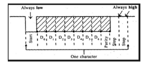
The term baud rate is used to indicate the rate at which serial data is being transferred. Baud rate = 1/ time for a bit cell
• A device such as INTEL 8251A can be programmed to do either asynchronous or synchronous communication, is often called USART (Universal Synchronous Asynchronous Receiver Transmitter).
RS-232C serial data standard:
• In serial I/O, data can be transmitted as either current or voltage.
• When data is transmitted as voltage, the commonly used standard is known as RS-232C.
• This standard proposes a maximum of 25 signals for the bus used for serial data transfer.
• The 25 signals of RS-232C are
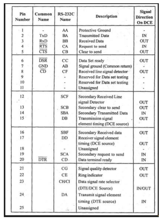
In practice the first 9-signals are sufficient for most of the serial data transmission scheme and so the RS-232C bus signals are terminated on a D-type 9- pin connector. • When all the 25 signals are used, then the RS-232C serial bus is terminated on a 25-pin connector.
- Serial Peripheral Interface (SPI) is an interface bus used to send data between microcontrollers and small peripherals such as shift registers, sensors, and SD cards. It uses separate clock and data lines, along with a select line to choose the device to talk to.
- SPI has a "synchronous" data bus, which means that it uses separate lines for data and a "clock" that keeps both sides in perfect sync.
- The clock is an oscillating signal which tells the receiver exactly when to sample the bits on the data line. This could be the rising (low to high) or falling (high to low) edge of the clock signal. When the receiver detects that edge, it will immediately look at the data line to read the next bit. Because the clock is sent along with the data.
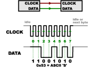
SPI
In SPI, only one side generates the clock signal called SCK for Serial ClocK. The side that generates the clock is called the "master", and the other side is called the "slave". There is always only one master, but there can be multiple slaves.
When data is sent from the master to a slave, it's sent on a data line called MOSI, for "Master Out / Slave In". If the slave needs to send a response back to the master, the master will continue to generate a prearranged number of clock cycles, and the slave will put the data onto a third data line called MISO, for "Master In / Slave Out".
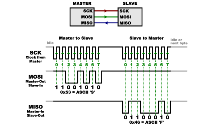
Master-Slave
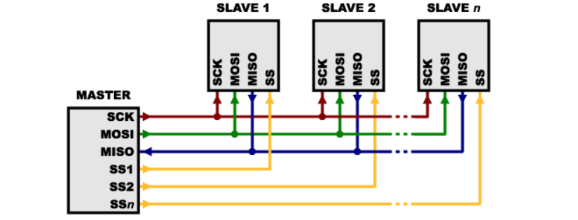
Multiple Slave
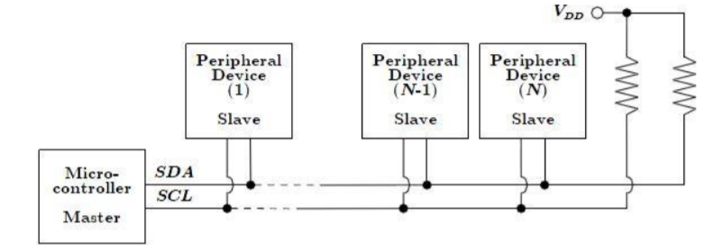
I2C is a multi-point protocol in which peripheral devices are able to communicate along the serial interface which is composed of a bidirectional serial data line (SDA) and a bidirectional serial clock (SCL).
The electrical interconnection beyond the wires is a single 4.7 kilo ohm pull-up resistor for each of the I2C bus lines. Consequently, a slave device writing to SDA needs to pull the line low for each ‘0’written; otherwise, it leaves the line alone to write a ‘1’, which occurs due to the lines being pulled high externally by the pull-up resistor. This is commonly known as a wired-AND configuration
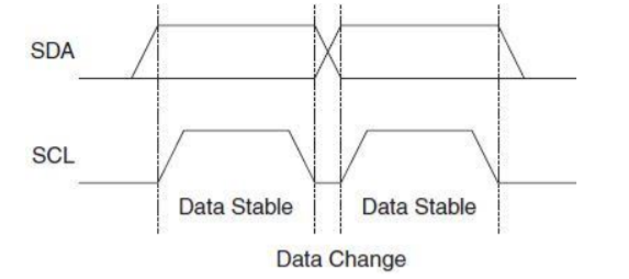
Transferring Bits on the I2C bus is accompanied by a pulse on the clock (SCL) line. The level of the data line must be stable when the clock line is high. The only exception to this rule is for generating start and stop conditions.
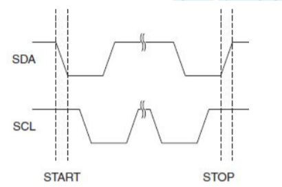
START and STOP conditions are signaled by changing the level of the SDA line when the SCL line is high.
All packets transmitted on the I2C bus are 9 bits long. An address packet consists of 7 address bits (27 = 128 possible addresses), one READ/WRITE control bit and an acknowledge bit. An address packet consisting of a SLave Address and a READ or a WRITE bit is called SLA+R or SLA+W, respectively. A data packet consists of one data byte and an acknowledge bit.

The master begins communication by transmitting a single start bit followed by the unique 7-bit address of the slave device for which the master is attempting to access, followed by a read/write bit.
The corresponding slave device responds with an acknowledge bit if it is present on the serial bus.
The master continues to issue clock events on the SCL line and either receives information from the slave or writes information to the slave depending on the read/write bit at the start of the session.
The number of bits transferred during a single session is dependent upon the peripheral device and the agreed-upon higher-level protocol.
ZigBee is a specification for high- level communication protocols using small low-power digital radios based on IEEE -802 standard for personal area networks.
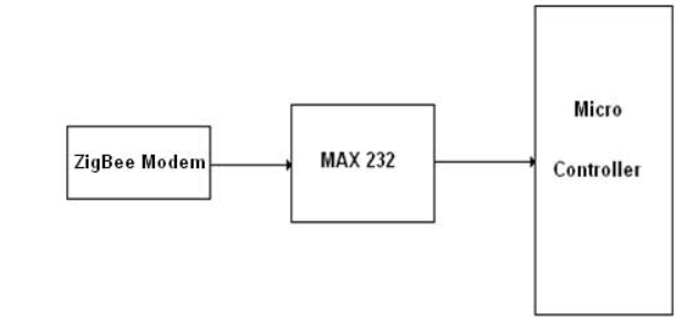
Figure shows how to interface the Zigbee with a microcontroller.
The Xbee modules work at the 2.4 GHz frequency which means smaller board and antenna size.
Xbee modules can transmit Digital, PWM, Analog or Serial RS232 signals wirelessly.
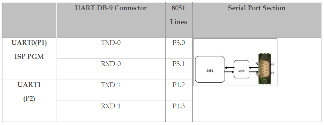
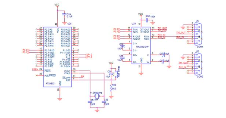
To communicate over UART or USART, three basic signals namely, RXD (receive), TXD (transmit), GND (common ground) are used to interface UART with 8051.
Pin Assignment with 8051
#include //Define 8051 Registers
Void serial(void); //Serial Communication Register
Void DelayMs(unsigned int); //Delay Function
Unsigned int i,j;
Unsigned char b[25],d;
//---------------------------
// Main Program
//---------------------------
Void main()
{
EA=1; //Enable All Interrupt
ES=1; //Enable Serial Port Interrupt
Serial(); //Serial Communication
While(1); //Loop Forever
}
//------------------------------------------
// Serial Communication Register Initialisation
//------------------------------------------
Void serial(void)
{
TMOD=0X20; //Timer1, Mode2
SCON=0X50; //Serial Mode1, Receive Enable
TH1=0XFD; //Baud Rate 9600bps
TR1=1; //Timer1 ON
}
//-----------------------------------------
// Serial Interrupt Function
//-----------------------------------------
Void serin (void) interrupt 4 //Serial Port Interrupt
{
If(RI==1) //Receive Interrupt Gets Enabled
{ //after Stop Bit get Received
d=SBUF; //Serial Buffer value moved to a variable
b[j]=d;
SBUF=b[j];
DelayMs(20); //Delay Function
j++;
}
SCON=0X50; //Initialising Receive and Transmit Interrupt
}
//---------------------------------
// Delay Function
//---------------------------------
Void DelayMs(unsigned int k)
{
Unsigned int i;
For(i=0;i<=k;i++);
}
Bluetooth
The HC-05 Bluetooth Module is an easy-to-use Bluetooth serial module. It is designed for transparent wireless serial connection setup. Its communication is through serial mode which makes it easy to interface with any microcontroller.
The HC-05 Bluetooth module provides a switching mode between master and slave mode. A single master device can be connected to up to several different slave devices. But, a slave device in the Bluetooth network can only be connected to a single master. The master device can send data to any of its slaves and request data from them as well, but the slaves are only allowed to transmit to and receive from their master.
The HC-05 Bluetooth module can be configured as a master device or a slave device with the help of AT.
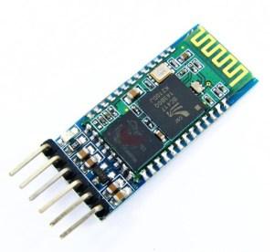
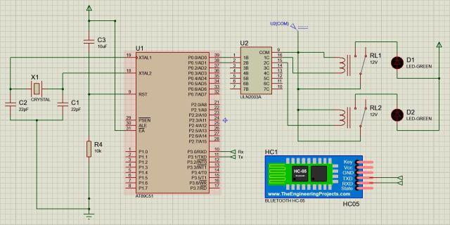
To enable Bluetooth communication, the HC-05 module is interfaced with the 8051 microcontroller via the built-in UART circuitry present in the microcontroller. And the data is transmitted in the form of packets. The 8051 microcontrollers have inbuilt pins P3.0 (RXD) and P3.1 (TXD) for receiving and transmitting the data from/to the HC-05 Bluetooth module respectively.
Circuit diagram to interface Bluetooth module and relay with 8051
● Step 1: If you are using Proteus or other simulation software or even hardware, select the AT89C51 or AT89S51 microcontroller .
● Step 2: Connect a 12 MHz oscillator between pin 18 and 19.
● Step 3: Connect two capacitors of 22pF, with one terminal on either side of the oscillator and the other terminal to ground, as shown below.
● Step 4: Set Pin 31,EA pin to HIGH by connecting it to the +5V DC source.
● Step 5: To make the RESET circuit, connect Pin 9 (RST) to +5V through a capacitor of 10µF and connect the same pin to +0V (GND) through a 10kΩ resistor or a potentiometer.
● Step 6: Connect two LEDs to the microcontroller such that they turn ON when a low pulse is given through Port 0’s output. For this, ULN2003a driver is used, pin P0.0 and P0.1 are connected to 1B and 2B of ULN2003A, respectively.
● Step 7: The output pins 1C and 2C of ULN2003a are given to one terminal of the coil of the relay and the other terminal of the coil of the relay is connected to the COM pin of ULN2003A which is connected to a DC supply.
● Step 8: One side of the contactor of the relay is connected to the cathode of the LED, and the anode is connected to the power supply. Connect the other side of the contactor to the COM pin of ULN2003A.
● Step 9: Connect the RXD (P3.0) and TXD (P3.1) of the 8051 microcontrollers to TXD and RXD pins of HC-05 Bluetooth module respectively.
● Step 10: VCC and GND pins of the HC-05 Bluetooth module are to be given to +5V/3.3V and GND, respectively, for the module to turn ON.
#include<reg51.h>
#include<stdio.h>
Sbit LED1 = P0^0; //Assign LED1 to pin P0.0
Sbit LED2 = P0^1; //Assign LED2 to pin P0.1
Void main()
{
Char mychar; // Assign a variable for the character to be received
TMOD = 0x20; // Set time Timer 1 in 8-bit auto-reload mode (mode 2)
TH1 = 0xFD; // FD = -3, to send/ receive the data at 9.6Kbps
SCON = 0x50; // Serial Control is set in Mode 1, with REN = 1 (reception ON)
TI = 0; // Initialize the Timer Flag
RI = 0; // Initialize the Timer
TR1 = 1; // Start the timer (Timer 1)
While(1) // Runs forever until power supply is cut off
{
While (RI == 0); // Wait till the data is received, as soon as the data is received completely, the RI flag is set
RI = 0; // Clear the RI flag to declare the availability for reception of another data
If (mychar == 'A') // If the data received through the Bluetooth module is the character 'A'
{
LED1 = 0; // Turn ON LED 1
}
Else if (mychar == 'a') // If the data received through the Bluetooth module is the character 'a'
{
LED1 = 1; // Turn OFF LED 1
}
If (mychar == 'B') // If the data received through the Bluetooth module is the character 'B'
{
LED2 = 0; // Turn ON LED 2
}
Else if (mychar == 'b') // If the data received through the Bluetooth module is the character 'b'
{
LED2 = 1; // Turn OFF LED 2
}
}
}
References:
❖ 8051 Microcontroller: An Applications Based Introduction Book by David Calcutt, Frederick J. Cowan, and Hassan Parchizadeh
❖ 8051 Microcontrollers: Internals, Instructions, Programming, and Interfacing Book by Subrata Ghoshal
❖ C and the 8051: Building efficient applications Book by Thomas W. Schultz
❖ MICROCONTROLLER Book by V. Udayashankara
❖ The 8051/8052 Microcontroller: Architecture, Assembly Language, and Hardware Interfacing Book by Craig Steiner