Unit - 2
Residential & Commercial Electrical System
Electrical Wiring
A process of connecting various accessories for distribution of electricity from supplier’s meter board to home appliances like lamps, fans and other domestic appliances is understood as Electrical Wiring. The wiring system selected will depend to an outsized extent on the kinds of service required.
Factors Affecting the Selection of Wiring
1. Durability
2. Safety
3. Appearance
4. Cost
5. Accessibility
6. Maintenance Cost
Types of Internal Wiring
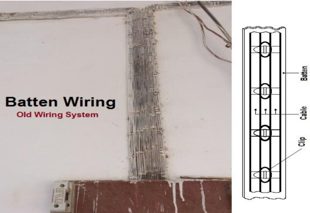
Batten wiring
a) CTS or TRS or PVC sheath wiring
b) Lead sheathed or metal sheathed wiring
Conduit wiring
a) Surface or open Conduit type
b) Concealed or underground type Conduit
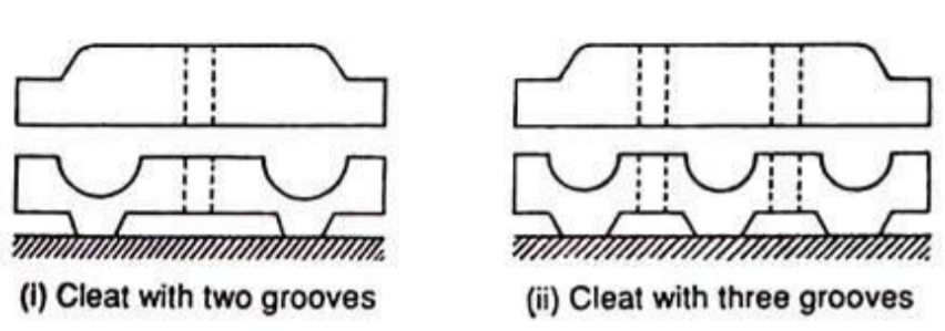
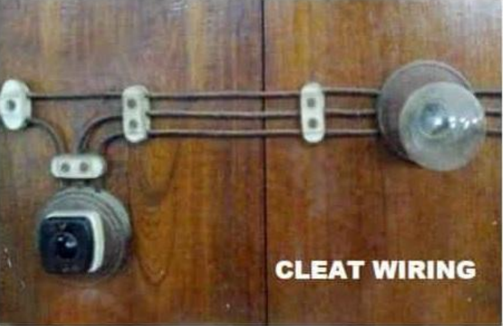
Cleat Wiring
Advantages:
Disadvantages
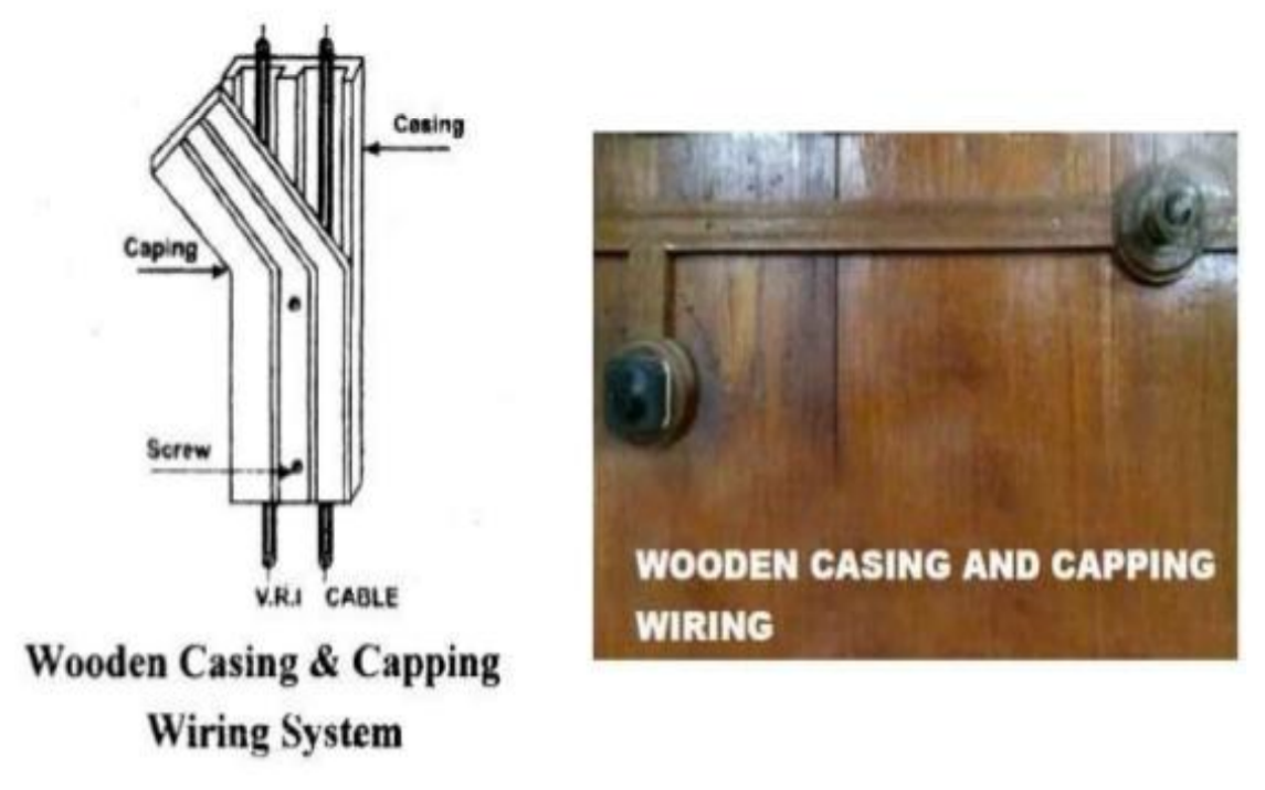
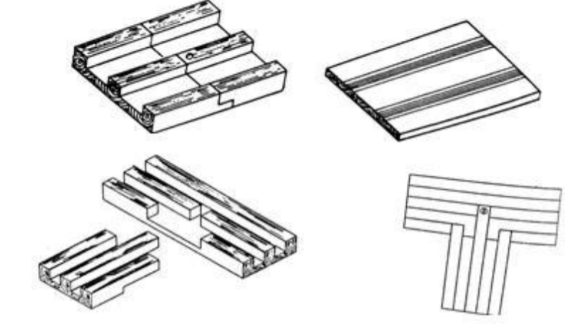
Casing and Capping Wiring
Advantages
Disadvantages
CTS or TRS or PVC Sheath Wiring
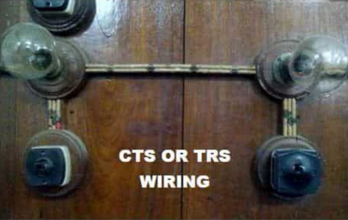
Advantages
Disadvantages
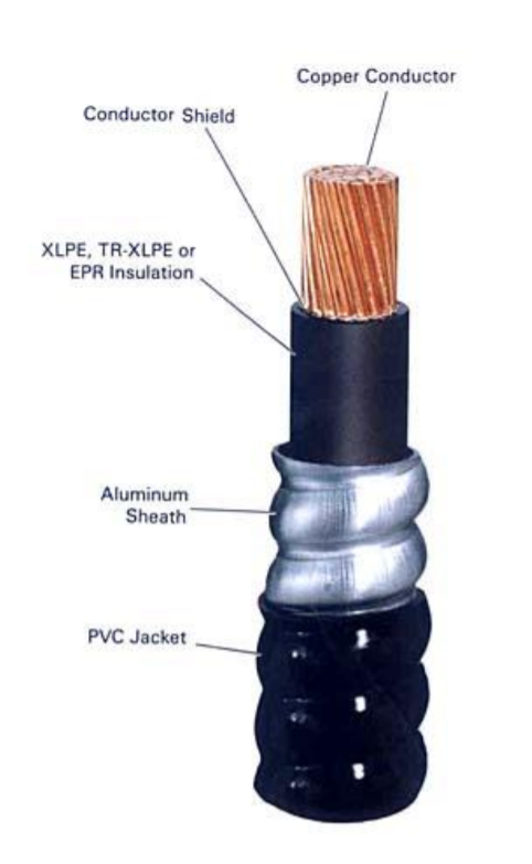
Metal Sheathed Wiring
Insulated wires cables are used in lead sheathed or metal sheathed wiring, TRS or PVC, with metal outer covering of about 1 mm. thick. The metal covering is known as sheathing and is made of lead – aluminium alloy containing about 95% of lead. The metal sheathed cables are run on wooden batten and are fixed thereto by link – clips. The entire metal sheathing proficiently earthed as per IS732-1983
Advantages
Disadvantages
Conduit Wiring System
Through tubes or pipes VIR or PVC cables taken and terminated at the outlets or switches / sockets. The tube or pipe is known as “conduit”. Conduit wiring may lane over the surface of the walls and ceiling or may be covered under masonry work.
Types of Conduits
1. Rigid steel / metal conduit.
2. Rigid PVC / non-metallic conduit.
3. Flexible steel conduit.
4. Flexible PVC / non-metallic conduit.
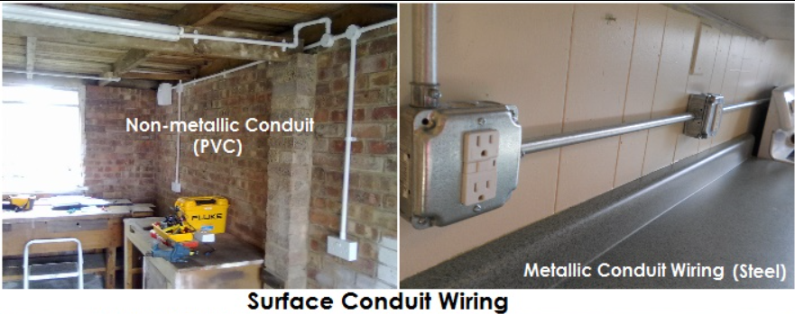
Surface Conduit Wiring
Coating with galvanized surface should be done for all steel conduits. Accessories of conduit must be threaded type. Minimum diameter of steel conduit should be 12.7 mm. By means of saddles conduit should be laid over the wooden gutties mm and should be fixed to the wall at an interval of not more than 1.2 m.
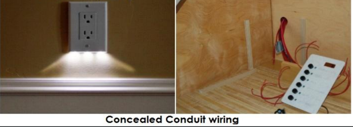
Concealed Conduit Wiring
During the period of building construction, the conduits (metal or PVC) are implanted along walls or ceiling in plaster. Using saddles less than 60 cm. apart the conduits are fixed. By means of GI wire of size 18 SWG the VIR or PVC cables are drawn into the concealed. In place of steel conduits PVC conduits are used. PVC conduits are low cost and saves labour time 25% to 50% related to the time taken while installing steel conduits.
Advantages
Disadvantages
Key takeaways:
The subsequent general instructions must be set aside in mind while performing the electrical wiring work:
Key takeaways:
Once a wire or a cable type is chosen supported the mechanical, chemical and thermal strength it'll be subjected to for the actual application, the cable size is to be selected next.
All conductors have resistance that forestalls a vast flow of current and in fact drop. For any given load, we must select a size of conductor that limits drop to an inexpensive value.
Furthermore, current through a wire causes heat thanks to the inherent resistance and proportional to the square of the present. There is a limit to the degree of warmth that the varied sorts of insulation can safely withstand. Even a bare wire must not be allowed to succeed in a temperature which may cause fire. Codes specify the ampacity (the max. current- carrying capacity in amperes) that's safe for a conductor of various sizes with different sorts of insulation and under different operating circumstances.
Cable size selection accounting voltage drop calculation
1. Using Pure Analytical Method (Without Table Reference)
2. Dc and Single-Phase Wires, Cables Size Selection
The size should neither be insignificant so as to have a big internal voltage drop and large heat nor be too big so as to rate too much. When choosing the size of a conductor or cable to be used in an installation there are two main aspects to be considered:
1. The voltage drop produced by the resistance of the cable of the required length must not surpass a boundary specified as a standard. Generally, drops of up to 2.5% of the supplied voltage is acceptable.
1% for feeder cables, 2% for branch circuits, and 2.5% for equipment taking power directly of the supply voltage drop is tolerable
2. The wire or cable necessity is it can carry the extreme current accountable to flow in the circuit without undue heating. The current rating of a conductor is defined as the maximum current a conductor can carry continuously without undue heating is its current rating.
3. Cable size choice may also be affected by the operating temperature of the cable and this should be compensated with derating factor
i. Cable size selection is also affected by grouping, their spacing distance, whether they are underground or in open air as well as insulation factors
Note: Each conductor of a cable is manufactured in the subsequent International standard dimensions in which the wires are circular and may be solid.
Standard nominal cross
section of bare wire (mm2) |
0.5 |
0.7 5 |
1 |
1.5 |
2.5 |
4 |
6 |
10 |
25 |
35 |
50 |
70 |
95 |
120 |
150 |
185 |
240 |
300 |
400 |
500 |
630 |
Purpose | Data cable |
|
|
|
|
|
|
|
| Electric cables | power |
|
|
|
|
|
| ||||
Cable Size selection accounting ambient temperature
If a cable is fitted in an ambient temperature of 25°C and loaded with the supreme valued current, the last temperature will be 70°C. Then, if the cable is fitted at a temperature above 25°C, the initial temperature of the cable will be higher, and the consecutive temperature will also be higher. Thus, to avoid the cable from overheating, we must make modifications to the current carrying capacity of the cable, if it is fitted in an ambient temperature above 25°C.
For rubber insulated conductor the maximum allowable heating up is expected to be reached with a temperature rise of 35℃ so that the limit temperature is fixed at 25°C. + 35℃ = 60℃. Thermoplastics insulating materials permit a surplus temperature of 45℃ giving a limit of 70℃.
For instance, for a general-purpose PVC at 35°C the correction factor is 0.94.
Table values of current dimensions are provided for a room temperature of 25°C and less.
Table beneath narrates the temperature correction factor (Ca) for ambient temperature.
Room temp  | 30 | 35 | 40 | 45 | 50 | 55 | 60 |
Temperature correction factor for value in table, Ca | 0.92 | 0.85 | 0.75 | 0.65 | 0.53 | 0.38 | 0.30 |
Cable size selection accounting number of conductors
If circuits were grouped with other circuits or if multicore cables were bunched with other multicores in an enclosure, the warmth dissipation properties of the circuits or cables would be reduced. the dissipation properties of the cable are reduced when there are more cables in the group. when cables are grouped, they would overheat if the cables were loaded to their ungrouped level. The figure of assembled circuits must be taken into account. Refer Table for correction factors Cg to account for grouping.
For instance, for 2 enclosed multicore cables bunched and clipped direct to a non-metallic surface, Cg
= 0.80. only 80 per cent of the single circuit current is permissible for 2 circuits. For three circuits, Cg = 0.70. only 70 per cent of the multicore current is allowed for 3 circuit. If a cable is grouped with three other circuits (4 in total), Cg = 0.65 when a cable is assembled with three other circuits (4 in total),
No. of multicore groups, or multiple circuit group | 1 | 2 | 3 | 4 |
Grouping correction factor, Cg | 1 | 0.8 | 0.7 | 0.65 |
When grouped with other cables capacity will reduce to I/z = Cg x Iz
If ambient temperature variation is encountered for the bunched cables, the collective correction factor of grouping and temperature will be C = Cg x Ca. So, the current capacities of each of the cables is reduced by a factor of C, i.e. I/z = C x Iz.
If the cable is run in heat-insulating material, capacity to dissipate heat will be reduced if the cable is run in heat-insulating material. To ponder this, a heat insulation correction factor Ci applied to the length of the cable enclosed in thermal insulation.
Thus, the joint effects of ambient temperature change, grouping and heat insulation utilization will result a combined correction factor C = Cg x Ca x Ci and I/z = C x Iz.
Cable size selection accounting protective device & correction factors
The design current Ib should be less than the protective device current rating of the circuit/ appliance. Value of In & Ib is selected from standard tables. For the defensive device to defend the cable against overload, the minimum cable rating, Iz = In or Iz In. Under normal condition (25OC, un-grouped, and with no heat insulation), the tabulated rated value of the cable Iz= It When one or all correction factors are to be accounted, to determine the corrected rating of the cable we use correction factor as divisor as
I/z = Min. It = In/Cg×Ca×Ci or I/z = It In/Cg×Ca×Ci
a factor of 0.725 is used When a rewireable fuse is to be used,
Now I/z = Min. It = In/Cg×Ca×Ci x 0.725 or I/z = It In/Cg×Ca×Ci x 0.725
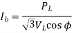
a. Single phase

PL is single phase continuous load; V is phase voltage and ø is power factor angle.
b. Three phases for three phase load PL, VL is line voltage and is power factor angle.
ii. Select cable type for desired application (for overhead, underground, indoor, outdoor, wet, dry etc) based on
iii. If over current protection is to be used apply correction factors for ambient temperature, grouping, and heat insulation
 Corresponding to the design current Ib select from standard tables the rating of the protection device and the lowest current carrying capacity of cable Iz = It to be selected will then be

For semi-enclosed fuses (i.e., rewireable fuse) divide further by 0.725.
for the circuit over current protection is not to be provided then,
cables minimum current carrying capacity to be selected as

Here Ca, Cg, and Ci are ambient temperature, group, and insulation correction factors.
iv. Check for the allowable voltage drop using the continuous current in the cable that is the design current.
If the voltage drop is higher than the allowed, choose the higher cross-section until the voltage drop is in the allowed range
Key takeaways:
SWITCH RATING
Switches are rated according to their electrical characteristics. The rating of a switch is determined by such factors as contact size, contact material, and contact spacing. There are two basic parts to a switch rating-the current and voltage rating. For example, a switch may be rated at 250 volts dc, 10 amperes. Some switches have more than one rating. For example, a single switch may be rated at 250 volts dc, 10 amperes; 500 volts ac, 10 amperes; and 28 volts dc, 20 amperes. This rating indicates a current rating that depends upon the voltage applied.
CURRENT RATING OF A SWITCH
The current rating of a switch refers to the maximum current the switch is designed to carry. This rating is dependent on the voltage of the circuit in which the switch is used. This is shown in the example given above. The current rating of a switch should never be exceeded. If the current rating of a switch is exceeded, the contacts may "weld" together making it impossible to open the circuit.
VOLTAGE RATING OF A SWITCH
The voltage rating of a switch refers to the maximum voltage allowable in the circuit in which the switch is used. The voltage rating may be given as an ac voltage, a dc voltage, or both.
The voltage rating of a switch should never be exceeded. If a voltage higher than the voltage rating of the switch is applied to the switch, the voltage may be able to "jump" the open contacts of the switch. This would make it impossible to control the circuit in which the switch was used.
Key takeaways:
Electrical equipment used in residential areas is usually certified by a third party that guarantees compliance with relevant standards. In this case, the device will display the certification mark of a certification body such as VDE, NF, AENOR, IMQ. Conformity marks are a voluntary manufacturer's process and mean regular verification of product quality by third-party laboratories. In the EU zone, CE marking is a mandatory self-declaration of free trade by manufacturers / importers.
(See Fig)

Fig. – Example of typical UK residential distribution board
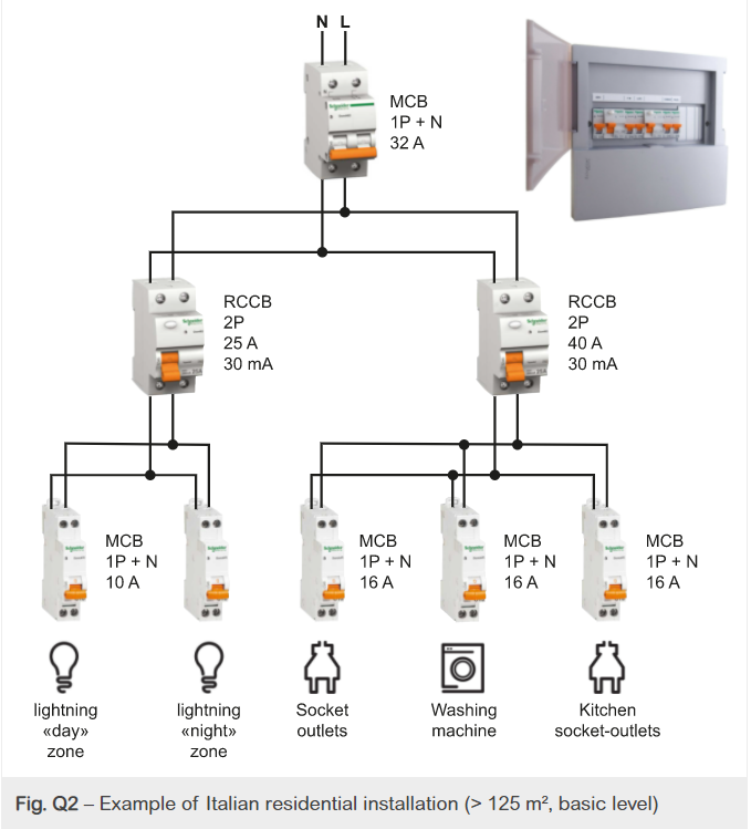
Fig. – Example of Italian residential installation (> 125 m², basic level)
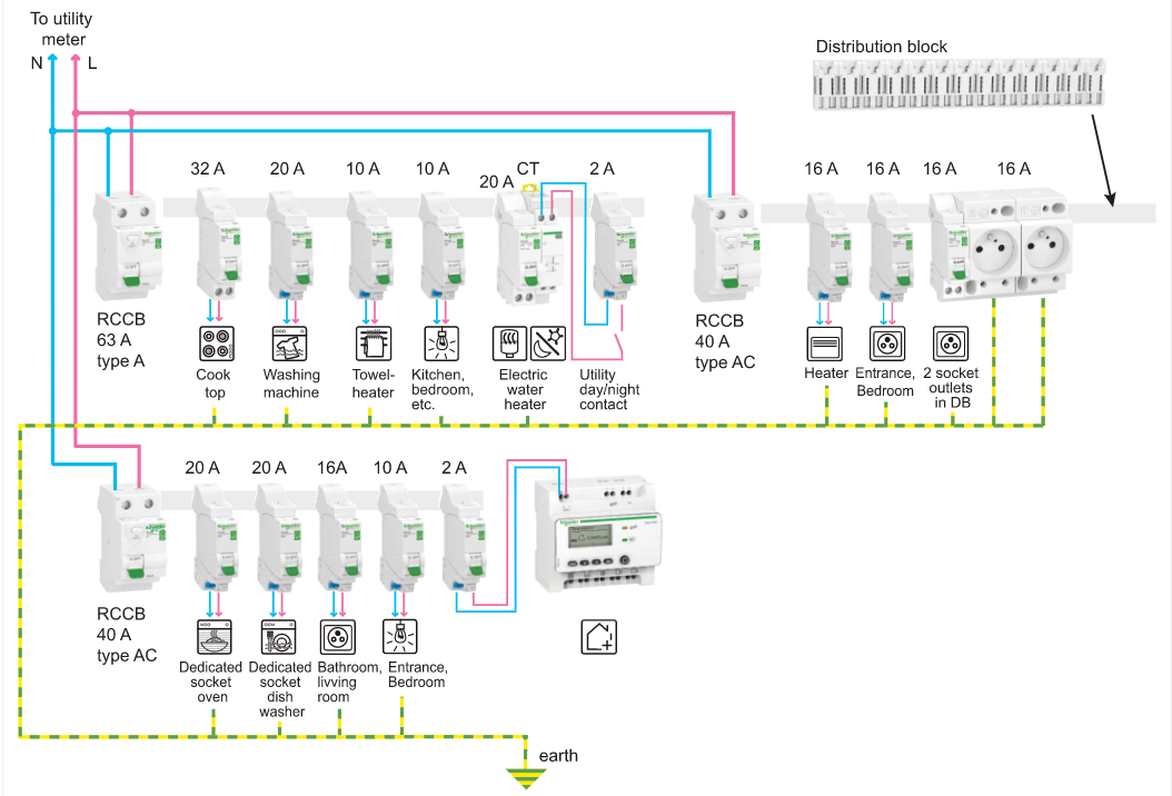
Fig. – Example of French residential installation (3 rooms with electric heater)
Distribution boards (usually only one in a residential area) usually include meters, and in some cases (especially if the supply utility imposes TT grounding systems and / or toll conditions that limit maximum permissible current consumption.), Includes input power differential circuit. -Circuit breaker with overcurrent trip. This circuit breaker is freely accessible to consumers.
For equipment within a TN grounding system, the supply utility typically protects the equipment with a sealed fuse cut-out just upstream of the meter (see Figure Q4). The user does not have access to these fuses.
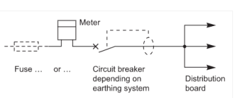
Fig. – Components of a control and distribution board
Input Power Circuit Breaker or Main Switch
(See Figure)
Consumers can operate this circuit breaker or switch as needed (for example, if the circuit breaker trips because the current consumption exceeds the allowed limit, close the circuit breaker again, open it in case of emergency or distribution board).
For TT systems, the rated residual current of the input circuit breaker must match the maximum ground impedance.
For example, if the earth impedance is less than 100 ohms, the rated residual current of the main RCBO must not exceed 500mA. Idn = 50 V / 100 ohm = 500 mA
In some countries, the rated residual current of the input circuit breaker is 300mA. In this case, the resistance of the ground electrode should be less than R = 50 V / 300 mA = 166 ohms.
In practice, the ground electrode resistance of new equipment should be less than 80Ω (R / 2).

a] France (CB) b] UK (switch-disconnector)
Figure – Examples of supply circuit breakers or switches from different countries
Distribution board (consumer unit) (See Figure Q6)
The configuration of this board is as follows:
Control panel for mounting input power circuit breakers and other control aids (if required), if required a distribution panel for storing MCBs and fuse units.
Connection accessories such as DIN rails for mounting MCBs, fuse bases, comb busbars to simplify device interconnection, accessories for fixing conductors, installation accessories such as neutral busbars and earth bars. Service cable ducts or conduits in surface mount or wall-embedded cable chase
Note: We recommend that you keep all relevant documents (photos, diagrams, characteristics, etc.) in a suitable location near the distribution board to facilitate future changes to your installation.
The board must be installed at a height that allows the user to access the operating handles that indicate the dial (in meters). Generally recommended heights are 1 meter above the floor (or less in some countries) to 1.80 meters (1.30 meters in situations where people with disabilities or the elderly are concerned).
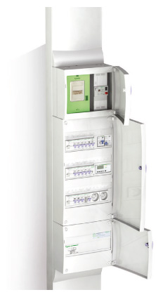
Fig. – Example of control and distribution board (France)
Surge Protector
Installing a surge protector (SPD) in the service location of an LV installation is highly recommended for installations involving sensitive (such as electronic) equipment that is very common today.
These devices must either be automatically disconnected from the installation in the event of a failure or protected by the MCB. See Protection against overvoltage and lightning.
Resistance value of ground electrode
If the TT scheme does not meet the 80Ω value of the electrode resistance, a 30 mA RCD must be installed to take over the leakage protection function of the input power circuit breaker.
If the ground resistance exceeds 80Ω, one or more 30 mARCDs should be used instead of the leakage protection of the input power circuit breakers.
Protection Devices
In the TT system, human protection is guaranteed by:
Protection against the risk of indirect contact with a medium sensitivity (300 mA) RCD (see Figure Q7) at the installation source (embedded in the input power circuit breaker or input feed to the distribution board).
This measure is for consumer-installed ground electrodes that require the connection of all Class I insulating equipment and exposed conductive parts of the equipment, and a protective ground conductor (PE) from the ground contacts of all socket outlets. It is related.
If the source CB does not have RCD protection, it is necessary to ensure human protection by double or reinforced insulation of all circuits upstream of the first RCD. If the distribution board is made of metal, care must be taken to ensure that all charging parts are doubly insulated (auxiliary clearance or insulation, use of covers, etc.) and the wiring is securely secured.
In TN systems, fault protection is guaranteed by:
Fault protection is guaranteed by the circuit breaker from which it was installed.
This measure relates to consumer-installed ground electrodes that require the connection of all Class I insulation equipment and protective ground conductors (PEs) from exposed conductive parts of the equipment.
For all earthing systems:
Essential protection with a 30mA sensitive RCD on the outlet circuit and the circuit that powers the bathroom. And recently, IEC60364 also requires the use of 30m ARCD in lighting circuits.
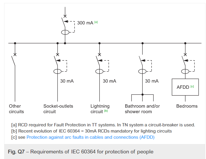
Fig. – Requirements of IEC 60364 for protection of people
Input power circuit breaker with instantaneous differential relay
in this case:
Insulation failure to ground can cause the entire equipment to shut down, if a surge protector is installed, its operation (that is, discharging the voltage surge to ground) will appear as a ground fault on the RCD, which can result in the installation being shut down.
Recommendation of appropriate Schneider Electric components
300mA differential and 300mA differential input power circuit breakers
High sensitivity 30mA RCD on the circuit to supply to the socket outlet (e.g., differential circuit breaker 1P + N type resi9)
High sensitivity 30 mA RCD on the circuit to bathrooms, shower rooms, laundry rooms, etc. (lighting, heating, outlets) (e.g., differential load switch type ID'clic)
Input power circuit breaker with type S time delay differential relay
This type of CB provides protection against ground faults, but the short time delay provides a measure of selectivity in the downstream instantaneous RCD. This makes it less likely that the input power supply CB will trip and result (for example, in the freezer) in the event of a lightning or other voltage surge cause. Discharging the voltage surge current to ground through the surge arrester does not affect the Type S circuit breaker.
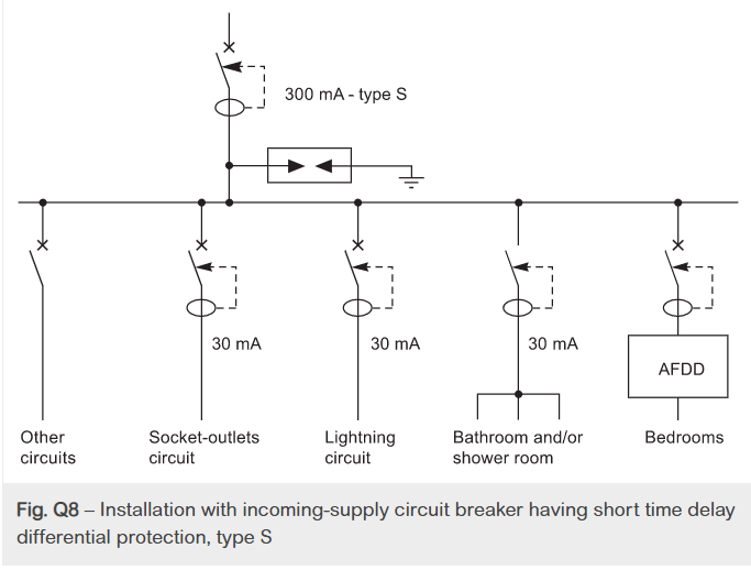
Fig. – Installation with incoming-supply circuit breaker having short time delay differential protection, type S
Input Power Circuit Breaker Without Differential Protection
In this case, human protection should be ensured in the following ways:
Class II level insulation down to the downstream terminal of the RCD
All output circuits from the distribution board should be protected at 30mA or 300m ARCD, depending on the type of circuit involved, as described in Chapter F.
In rare cases (but always possible), if a voltage surge arrester is installed upstream of the distribution board (to protect sensitive electronics such as computers, TVs, Internet access boxes), the device will be automated from installation. It is essential to be disconnected.) Failure. Some devices employ interchangeable fusion elements. However, as shown in Figure Q9, the recommended method is to use a circuit breaker.
Recommendation of appropriate Schneider Electric components
Figure refers to:
1 = Input power circuit breaker without differential protection
2 = Automatic cutting device (if a lightning arrester is installed)
3 = 30 mA RCD for each circuit that powers one or more outlets (e.g., differential circuit breaker 1P + N type Declic Vigi)
4 = 30 mA RCD on the circuit to bathroom and shower room (lighting, heating, outlet) (e.g., differential load switch by clicking on type ID) or 30 mA differential circuit breaker per circuit
5 = 300 mA RCD (for example, differential load switch on all other circuits.
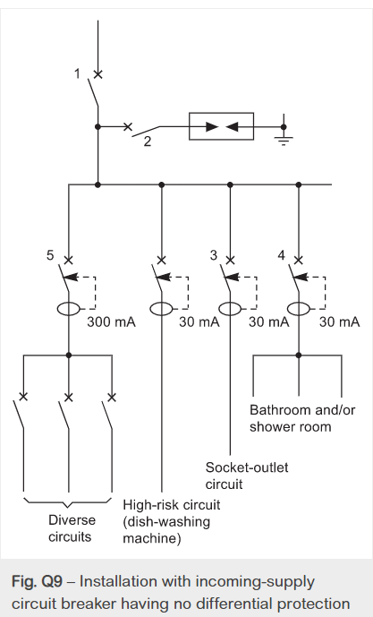
Fig.– Installation with incoming-supply circuit breaker having no differential protection
Key takeaways:
This section applies if 1 ohm is still in circulation in the document.
The ground calculation to determine a safe system ground (ground) is usually shifted from any resistance value of less than 1 ohm. It's still too common to see this outdated measure of installed success appearing in the Client / Employer Requirements Specification (ER). Grounding calculation design as part of safety briefs.
EC-based EN50522 Grounding of power supply equipment over 1 kV a.c. Implemented in 2010. It also replaces the BS 7354 (1990) Code of Practice for the design of high voltage open terminal stations. BS 7430 Earthing Protection was updated in 2011 as well.
Probabilistic Approach
The first really big step change is the recognition that the safety of electrical systems is stochastic in nature.
What do you mean?
For many years, engineers have used a deterministic approach to acceptable step and touch voltages. Therefore, it is based on recognized international standards such as IEEE-80 / BS 7354 / BS 7430. However, the weakness of the "deterministic" approach was that certain safety standards were applied to all sites. It is regardless of the physical context of the site. For example, industrial land has a very different safety situation than schools and pools. You may have a child with bare feet and probably a wet body.
Or, as another example, a T & D (transmission and distribution) manned substation in the middle of an urban environment can have very different risk characteristics than an unmanned DNO (distribution network operator) substation. Remote areas where it is difficult to reach the rural environment.
Here, a "stochastic" approach was introduced to assess the risks (potentials and outcomes) of individual sites using well-understood risk management procedures. This approach considers the risk of fibrillation (from the step voltage or touch voltage) and the risk of co-occurrence (from the frequency of failures and the circulation of people on or near the site). Thanks to Charles Dalziel's work, target mortality / survival factors (IEC 60479-1) associated with various social risks within the general population are provided.
Grounding Calculation for Safety-Applied Research
The above social risks are associated with the typical population of the "general public". The population is made up of people with a vast array of physical (and mental) variables. From gender, age, size, body shape, BMI level, mental endurance, etc. Some of the sampled populations may have a variety of additional medical conditions that may increase their sensitivity to body current / stress voltage.
The latest standards try to take this viability factor into account. There are subtle differences between the IEEE and IEC standards when it comes to calculating body current. However, in all cases it is important to understand that in this context "probability" does not mean that everyone is expected to survive. This is followed by design questions for compliant safety calculations.
How much survival rate does your safety ground calculation allow?
Accepting it statistically, designing a 100% survival rate is not reasonably feasible. What do you think is the "acceptable" number of casualties (deaths)? 5% ... 30% ... 50%?
It's a cool idea. You can also achieve the highest survival rate with a grounding arrangement. When 100 people pass or are near the facility to facilitate safety calculations. Statistically, with a compliant design, at least 5 out of 100 people may not be able to go home. Indeed, some of the first survivor injuries can have life-shortening or life-changing consequences that do not appear in the first mortality figures! And this envisions a scenario where Earth is considered "safe", technically safe, and in good condition. Imagine the number of casualties for a non-compliant design.
Safe Ground Calculation-Ignorance is Bliss 
Power system-related failures and surges are known to occur frequently throughout the network. Whether it is a switch, lightning, or a failure / failure. The rise of the Earth Potential events are real and their frequency is measured and monitored by responsible operators. A well-designed grounding / grounding system usually means that an EPR (grounding potential rise) event goes unnoticed. This can foster a disdainful false sense of security. But without a doubt, the risks are very real and the consequences of inadequate or inadequate design can be absolute.
Electrician with advances in technology such as visual software tools.
Safe Grounding Calculation Automation
Technology-based automation has entered many aspects of our daily lives. For example, from self-driving cars to office Wi-Fi enabled espresso coffee makers. Grounding The latest safety calculations for grounding designs are no exception.
EN 50522 – Grounding above 1 kV recognizes that the scale, scope, and complexity of ground safety calculations exceed those most rational engineers attempt with manual calculations. Also, manual calculations require the use of (at best) simplified equations, resulting in inaccurate scenario safety calculations, inadequate design, and all of the above consequences (risks). There is likely to be.
The latest update to the standard recognizes advances in FEA (Finite Element Analysis) software tools and their contribution to a better understood and safe world. FEA tools run by competent engineers, such as CDEGS, can handle large amounts of data in safety calculations. This was often previously unstudied without securing unlimited cash.
Note – Bill Gates, the founder of Microsoft, better understood that technology is not a "silver bullet" for all issues when he said:
The first rule of technology used in business is to improve efficiency with automation applied to efficient operations. Second, applying automation to inefficient operations increases inefficiencies. (Bill Gates)
The automation of safety calculations depends on the technically safe "input" and the level of competence of the people who use it. Bill Gates understood the limits of his software. He always recommends checking his limits (see this article for comparison) along with the skill set of the person using it.
Have a professional electrician perform these installations and make sure that you have completed the work to create the code for the safety and protection of your property and personnel.
Breaker
The job of the breaker is to protect you and your property from electrical short circuits. Hire Brandon Electric to make sure the breaker is installed properly.
Dedicated outlets and circuits
Certain electrical connections may be required to install new equipment. Please contact us to ensure compatibility with your existing system before purchasing new equipment specific to your requirements.
Landscape and sign lighting
Proper landscape and sign lighting can add elegance and safety to your property.
Installation requires proper sizing of underground wiring. The right type of light to suit your needs.
Meter Bank and Meter Can
A meter bank or meter can is where the building where power consumption is measured is powered on. Brandon Electric stocks a variety of Meter Bank parts for hard-to-find parts.
Panel box
The panel box is the heart of the electrical system. When it comes to panel boxes, there are many options. We can guide you through your choices.
Remodelling, addition, new construction
Choosing an electrician for a new project is an important step in the progress of the project. With Brandon Electric, you don't have to worry about deadlines or unnecessary stagnation.
Single-Phase and Three-Phase Equipment
Commercial power is typically supplied by your utility in 120-240v or 277-480v single-phase or three-phase power. Brandon Electric has experience with both types of power supplies.
The lighting scheme should be as follows:
The following factors should be considered when designing a lighting scheme:
Factor # 1. Lighting level:
This is the most important factor. Sufficient lighting is the basic way to see the surroundings, because unless it is a light source itself, the object will only have the brightness it needs when it is illuminated. It is the job of lighting to give objects distributed brightness. Body color has the property of reflecting light to varying degrees. It is this difference in brightness that gives the essential perception of detail. Each type of work has a range of brightness that best suits the output. This means minimizing fatigue and providing maximum output in terms of quality and quantity.
The degree of illumination to give an object the required brightness depends on:
(I) Size of the object seen and distance from the observer-The greater the distance of the object from the observer and the smaller the size of the object, the greater the lighting required for its proper perception.
(II) Object-Background Contrast-The greater the contrast between an object's color and its background, the more lighting is needed to properly distinguish the object. Objects that are seen for long periods of time require more lighting than casual work. Similarly, moving objects require more lighting than stationary objects.
According to the ISI, the required lighting levels for different parts of the building are listed below.
Location | Illumination Level in Lux |
Entrances, hallways Living room Dining room Bed room General Dressing tablets, bed heads Table games Games or recreation room Kitchen Kitchen sink Laundry Bathroom Bathroom mirror Sewing Workshop Stairs Garage Study | 100 300 150 300 200 300 100 200 300 200 100 300 700 200 100 70 300 |
According to the ISI, the lighting levels required for different types of traffic routes are listed below.
Classification of Lighting Installation
| Type of Road
| Average Level of Illumination on Road Surface
|
Group  | Important traffic routes carrying fast traffic | 30 |
Group  | Other main roads carrying mixed traffic like main city streets, arterial roads, through ways etc. | 15 |
Group  | Secondary roads with considerable traffic like principal local traffic routes, shopping streets etc. | 8 |
Group  | Secondary roads with light traffic | 4 |
Factor # 2. Lighting uniformity:
The human eye automatically adjusts to the brightness in the field of view. Lack of uniformity can lead to eye fatigue and reduced productivity due to the need to adjust the pupils and iris of the eye more often. Best visual performance has been found when the range of brightness in the field of view is 3: 1 or less, which can be achieved by using general lighting in addition to local lighting.
Aside from considering fatigue, local lighting, which does not use anything that matches general lighting, creates a psychological sensation of loneliness, darkness, and unkindness. Therefore, the modern trend is towards the adoption of “local and general lighting” and “general lighting directed to the work surface”, especially in mass production factories, offices, drafting offices, stores and the like.
Factor # 3. Light color:
The appearance of the body color is completely dependent on the color of the incident light. In general, the composition of light should make the colors look natural. In other words, the appearance of artificial light should not be much different from the appearance of daylight. Today’s daylight fluorescent lamps allow you to economically illuminate large spaces with artificial daylight, providing excellent color rendering and a sufficiently high level. For certain applications, such as street lights, if you don’t need to distinguish different components by color, the color of the light is less important and you can use a highly efficient discharge lamp that causes color distortion.
Factor # 4. Shadow:
In luminaires, the formation of long, hard shadows are considered a drawback as it causes eye fatigue. The complete absence of shadows does not necessarily mean the ideal condition of the luminaire. Perhaps contrary to public opinion, some shadow is desirable for artificial lighting. The purpose is to give shape to solid objects so that they can be easily recognized. Objects illuminated by shadowless light are flat and uninteresting, lose their contours, and make it difficult for the eyes to correctly determine the shape of the object. However, there is one exception to this. In other words, shadowless light is essential in a drawing office that looks at a flat surface. Otherwise, the shadows will get in the way of your work.
Hard and long shadows can be avoided in the following ways:
(I) Using a large number of small luminaires mounted at a height of 2.5 meters or more,
(II) Use a glove on the filament lamp or use an indirect lighting system and use a wide surface light source.
Factor # 5. Glare:
It may be direct or reflective. That is, it may come directly from the light source, or it may be the brightness reflected from a desktop, nickel-plated mechanical parts, calendar paper, etc.
Direct glare from a light source is more common and often interferes with vision. A glance at the sun reveals that a very bright light source causes acute eye discomfort. Light sources that are much less bright than the sun, such as incandescent filaments and gas lamp incandescent mantles, can also cause discomfort due to direct glare. Reflective glare is glare that is visible as a glint or reflection of a light source on a polished surface.
A bright light source near the middle is acceptable by placing it at a height above normal field of view.
Metal reflectors for industrial lighting usually have a skirt around the edge of the reflector
Factor # 6. Mounting height:
The mounting height is largely determined by the type of building and the type of lighting scheme used. In direct sunlight, in rooms with large floor areas, the luminaire should be installed as close to the ceiling as possible. Lowering them not only reduces the uniformity of lighting, but also increases the glare in the field of view without significantly increasing utilization. In the rare cases of small rooms with high ceilings, there are things that can be gained by lowering the luminaires, but again, using filament lamps with focusing reflectors and mounting them high may be a better solution. Hmm.
In the case of indirect and semi-indirect lighting, of course, it would be desirable to hang the luminaire well below the ceiling in order to provide reasonably uniform lighting to the ceiling. In practice, this is usually interpreted to mean that the length of the suspension tube should be one-fourth to one-third of the horizontal spacing between rows of luminaires.
Unfortunately, it is very commonly recognized that a minimum clearance of 2.5 meters between the luminaire and the floor is required, so it is often impossible to hang them so far. Therefore, in a room with a low ceiling, uneven ceiling lighting is inevitable. This is fine as the ceiling is not a working surface.
Factor # 7. Luminescent spacing:
Correct spacing is very important to provide uniform illumination throughout the area and therefore eliminates the relatively dark areas that are often seen with poor fitting spacing.
For direct and semi-direct luminaires, the ratio of the horizontal spacing between rows to the height of the luminaire from the work surface depends to a large extent on the candle power distribution curve of the luminaire. For fluorescent lights, it is recommended to set the value of this ratio to 1 and the upper limit to ¾. For tungsten lamps in combination with focusing reflectors, the ratio of spacing to height should be approximately 0.6.
For indirect and semi-indirect luminaires, it is advisable to aim for a horizontal spacing between rows that is approximately equal to the height of the ceiling above the work surface. The horizontal spacing should not exceed 1.5 times this height.
For fluorescent emitters, it is common practice to combine two or more emitters end-to-end so that they share a common outlet. In fact, continuous rows of luminaires often work, especially if the specified lighting is quite high.
Factor # 8. Surrounding wall color:
The lighting in any room depends on the light reflected from the walls and ceiling. White walls and ceilings reflect lighter than colored ones.
Key takeaways:
Earthing or grounding is the process of transferring an immediate discharge of electricity directly to the ground plate using a low resistance electrical cable or wire. Earth is one of the most important aspects of electrical networks because it is the easiest to use and makes dangerous power supplies much safer to use.
If a short circuit occurs due to weak insulation or leakage due to damage, the ground wire safely removes excess electricity and passes it to the dormant ground. All this is done without undue complexity due to its unique and inexpensive construction, design and setup.
Why do electrical networks need a grounding system?
Some people are rethinking the need for grounding equipment and additional construction electrical materials, especially in large residential or commercial projects. If you are already using the highest quality equipment and performing regular maintenance, why do you need a ground?
The answer lies in the fact that life is unpredictable and you always have to be prepared for the unexpected. The safety provided by grounding or grounding systems is simple, making buildings and electrical boxes very low cost and shock free.
Grounding or grounding benefits in electrical systems
1. Overload Protection – Grounded systems are very useful in scenarios where excessive power surges occur. This simple form of surge protection instantly prevents appliances and devices from being lifted by excess power, saving data and equipment.
2. Voltage Stabilization – When calculating the appropriate amount of power distributed between voltage sources, the Earth provides its universal reference point. Grounding removes guesswork from voltage stabilization and prevents the circuit from overloading or exploding.
3. Preventing Damage, Injury and Death-Fuse blows and circuit breaker trips are far more welcome than electric fires and shocks that can cause serious safety problems for people and property. Basically, grounding protects against equipment, property, data loss, and injury or death.
Common type of ground used in electrical work projects
Plate Type – In plate grounding systems, components such as wires, rods, pipes, plates and conductors are made of copper, cast iron or galvanized iron. It is 2 feet square and has a 0.25-inch-thick copper or iron plate embedded in it. An earth pit with bolts placed vertically and layers of salt and charcoal placed from the bottom of the pit to a certain level. The depth at which the plate needs to be filled is typically about 8-10 feet above the ground.
Pipe Type – Due to its reliability, durability and ease of handling, pipe type grounding is often used in home and office electrical equipment, power lines, etc. Also called a ground electrode pipe, this is the most common and preferred grounding system type. Copper pipes are also used for this type of grounding. The length of this pipe depends on the type of soil, the water content and the current flowing. Pipes are typically 1.5 inches in diameter, but can vary in length from 2.75 feet to 15.5 feet in rocky, dry soil. In water-rich soil.
Key takeaways:
References:


