Unit - 3
Illumination Systems
Light: The radiant energy from the hot body that gives vision to the human eye is light. This is commonly expressed in Q, in lumens time, and corresponds to watt hours.
Luminous flux: The overall measurement of light energy emitted per second forms the illuminate. It is indicated by the symbol F and is measured in lumens. The idea of luminous flux helps to specify the output and efficiency of a particular light source.
Luminous intensity: Luminous intensity in all specified directions is the luminous flux emitted by a light source per unit solid angle, measured in the direction in which the intensity is required. It is represented by I and is measured in candela (cd) or lumens / steradians. If F is the luminous flux emitted from the light source within the solid angle of ω steradian in a particular direction, then I = F / ω lumen / steradian or candela (cd).
Lumen: Lumen is a unit of luminous flux. A light source with an intensity of 1 candle power in all directions defines the amount of luminous flux emitted into a space represented by a unit of solid angle.
Lumen = candle power * solid angle = cp * ω
The overall lumen given by one candela source is 4π lumens.
Candle power: Candle power is the light emission capacity of a light source in a particular direction and is defined as the number of lumens emitted by the light source at a unit solid angle in a particular direction. It is indicated by the symbol C.P.
C.P. = lumen / ω
Lighting: When light hits one of the surfaces, the phenomenon is called lighting. This is defined as the number of lumens that fall on the surface per unit area. Indicated by the symbol E, measured in lumens or metric candles or lux per square meter. If the flux of F lumens hits the surface of region A, the illumination on that surface is E = F / A lumens / m2 or lux.
Lux Or Metric Candles: This is a unit of illumination and is defined as the luminous flux that falls per square meter on a surface 1 meter away perpendicular to the rays from a 1 square meter light source. Footcandle: This is also a unit of lighting and is defined as the luminous flux that falls per square foot. This luminous flux is perpendicular to the light beam from one candle-powered light source and is one foot away.
1 footcandle = 1 lumen / ft2 = 10.76 m candle or lux
Candle: A unit of luminosity. It is defined as 1/60 of the luminosity per cm2 of a blackbody radiator at the platinum solidification temperature (2,0430K).
Average Horizontal Candle Power: Defined as the average of candle power in all directions in the horizontal plane, including the (M.H.C.P) light source. Average Spherical Candle Power: (M.S.C.P) This is defined as the average candle power in all directions and planes from the light source.
Average Hemispherical Candle Power: (M.H.S.C.P) Defined as the average of candle power in all directions above and below the horizontal plane passing through the light source.
Reduction factor: The reduction factor of the light source is the ratio of the average spherical candle power to the average horizontal candle power.
Reduction factor = M.S.C.P. / M.H.C.P.
Lamp efficiency: Defined as the ratio of luminous flux to input power. Expressed in lumens per watt.
Specific Consumption: Defined as the ratio of input power to average candle power. Expressed in wattage per candela.
Brightness: When the eye receives a large amount of light from an object, it is said to be bright. Brightness is an important amount of lighting. Whether light is produced by or reflected from an object is all the same. Brightness is defined as the luminosity per unit projected area of either a surface light source or a reflective surface and is represented by L. If the surface area A has the effective luminous intensity of the I candela in the θ direction with respect to the normal, the brightness (luminance) of the surface is
L = I / acosθ
Brightness units are candela / m2 (knit), candela / cm2 (stilb), or candela / ft2.
Glare: -The size of the pupil opening of the human eye is controlled by the iris. When the eye is exposed to a very bright light source, the iris automatically contacts to produce the amount of light allowed and prevent damage to the retina. This reduces sensitivity, so other objects in the field of view are only incompletely visible. In other words, glare is defined as the brightness in the field of view of such a character, causing discomfort, discomfort, and visual interference.
Space Height Ratio: -Defined as the ratio of the distance between adjacent ramps to the height of their peaks.
Space Height Ratio = 
Utilization or Utilization Factor: -Defined as the ratio of total lumens reaching the work surface to the total lumens emitted by the ramp.
Utilization or Utilization Factor = 
Maintenance Factor: Since the lamp collects dust, dirt, and smoke, it emits less light than when it is new, and similarly, it does not reflect dust, dirt, and walls and ceilings after being covered with smoke. The output of the same light that is reflected when they are new. Lumen The ratio of lighting under normal working conditions to lighting when things are perfectly clean is known as a maintenance factor.
Maintenance Factor=
Depreciation Factor: This is simply the opposite of the maintenance factor and is defined as the ratio of the first maintained meter candle to the last maintained meter candle in terms of work. Its value is 1 or more.
Factors of wasted light: Whenever a surface is illuminated by multiple light sources, there is always a certain amount of wasted light because the light overlaps at the edges of the surface and falls out. This effect is taken into account by multiplying the theoretical required lumens by 1.2 for rectangular areas and 1.5 for objects such as irregular areas, statues and monuments.
Absorption rate: It may absorb light in places where smoke can enter, such as foundries. The ratio of total lumens available after absorption to the total lumens emitted by the light source is called the absorption coefficient. Its value varies from 1 in a clean atmosphere to 0.5 in a foundry.
Beam Factor: The ratio of the projector's beam lumens to the lumens given by the ramp is called the beam factor. This factor takes into account the light absorption of the projector lamp's reflector and front glass. Its value varies from 0.3 to 0.6.
Reflection coefficient: When a ray hits the surface, it is reflected from the surface at the angle of incidence, as shown in the fallow diagram. A specific part of the incident light is absorbed by the surface. The ratio of reflected light to incident light is called the reflectance coefficient. Always less than
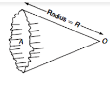
Plane Angle: A plane angle is the angle formed by two convergence lines at a point in the plane. It is represented by the Greek letter "θ" (theta) and is usually measured in degrees or radians.
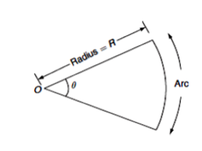
𝜃 =  𝑟𝑎𝑑𝑖𝑎𝑛s
A radian is defined as the angle formed by a circular arc whose length is equal to the radius of the circle.
Solid Angle: A solid angle is the angle formed by an area at a point in space. That is, the angle surrounded by the volume that is on the surface and is formed by the many lines that intersect at that point. It is usually represented by the symbol "ω" and is measured in steradians.
𝜔 =  =
= 
The maximum solid angle made at a point is due to the sphere in its center. If r is the radius of the sphere, its surface area is 4π2, and the distance from the center of that surface area is r, so the solid angle of the angle formed by its surface at that center is r, therefore, solid angle subtended at its centre by its surface,
𝜔 =  =4𝜋 𝒔𝒕𝒆𝒓𝒂𝒅𝒊𝒂𝒏s
Steradian: A unit of solid angle, defined as the angle on the surface of a sphere that corresponds to the square of the radius.
Key takeaways:
When the polished surface is exposed to light, the light is reflected back. This is good for lighting, but it causes glare that is harmful to the eyes.
When light hits a rough surface such as painted ceiling, frosted glass, or paper. Light is diffused in all directions, so there is no effect of glare on the eyes. Therefore, this method is used for internal or external lighting.
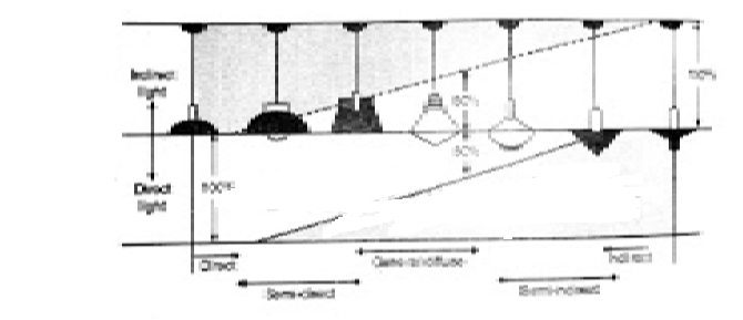
The types of lighting schemes are:
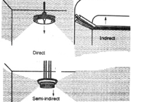
(A) Direct lighting.
(B) Semi-direct lighting.
(C) Semi-indirect lighting.
(D) Indirect lighting.
(E) General lighting.
(a) Direct lighting scheme:
This method makes most of the light sources available on the work surface, with very little waste.
Light energy is a light source, suspended and light is diverted by properly shaped reflectors or globs. Fewer lighting units are required, reducing the overall cost of the lighting scheme.
This system is the most efficient, but the drawbacks of this system are the dark shadows on the work plate and the glare on the eyes.
HL-lower hemisphere
UL-Upper Hemisphere
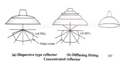
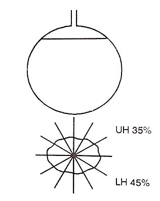
(b) Semi-Direct Lighting Scheme:
2. This is achieved by providing a semi-direct reflector. Such a scheme is best suited for tall rooms. Avoid glare and use diffused bulbs.
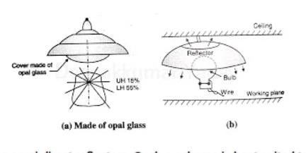
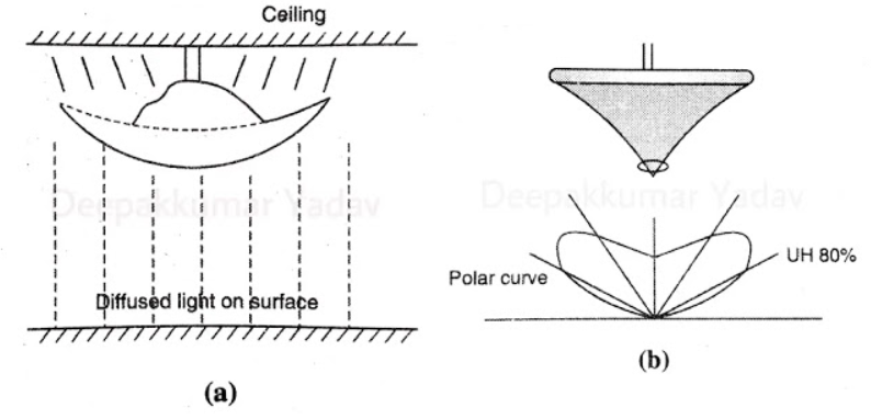
(c) Semi-indirect lighting scheme:
2. This provides comfortable lighting without glare and the shadows are very soft. The scheme is costly. However, it is used for upholstery purposes. The bowl is a translucent type.
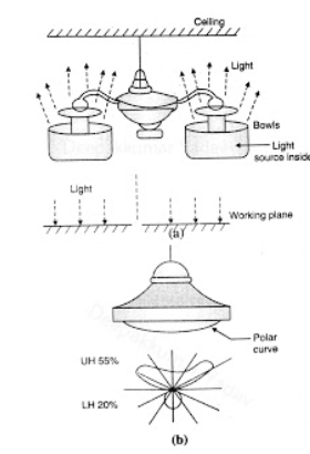
(d) Indirect Lighting Scheme:
(e) General lighting scheme:
Key takeaways:
A lamp that operates on the principle of the incandescent phenomenon is called an incandescent lamp. In other words, a lamp that operates by shining the filament with the current flowing through the filament is called an incandescent lamp.
How do Incandescent lamps work?
When an object becomes hot, the atoms in the object are thermally excited. If the object does not melt, the orbital electrons outside the atom will jump to higher energy levels due to the energy supplied. These higher energy level electrons are not stable and fall back to lower energy levels again. This radiation has different wavelengths. Some of the wavelengths are in the visible wavelength range, and a significant portion of the wavelengths are in the infrared range. Electromagnetic waves with wavelengths within the infrared range are thermal energy, and electromagnetic waves with wavelengths within the visible range are light energy.
Incandescent light means heating an object to produce visible light. Incandescent lamps work on the same principle. The simplest form of artificial light source that uses electricity is an incandescent lamp. Here, an electric current is used to flow through thin, thin filaments to produce visible light. The electric current raises the temperature of the filament, causing it to emit light.
Energy level. While falling from a higher energy level to a lower energy level, the electrons emit their extra energy in the form of photons. These photons are emitted from the surface of an object in the form of electromagnetic radiation.
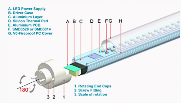
Construction of Incandescent Lamps
The filament is connected to two leads. One lead is connected to the foot contact and the other is terminated with the metal base of the bulb. Both leads pass through a glass support mounted at the bottom center of the bulb. Two support wires, also attached to the glass support, are used to support the central part of the filament. The foot contacts are insulated from the metal base by an insulating material. The entire system is encapsulated with coloured or fuffale coated or clear glass bulbs. Depending on the rating of the incandescent lamp, the glass bulb can be filled with an inert gas or kept in a vacuum.
Incandescent filaments are airtightly exhausted with glass bulbs of the appropriate shape and size. This glass sphere is used to isolate the filament from the surrounding air in order to prevent oxidation of the filament, minimize the customary current surrounding the filament and keep the filament warm.
The glass bulb is either kept in a vacuum or filled with an inert gas such as argon, which contains a small amount of nitrogen at low pressure. The inert gas is used to minimize the evaporation of filaments during lamp use. However, the convection of the inert gas in the valve increases the likelihood of filament heat loss during operation.
Again, the vacuum has excellent insulation, but it promotes the evaporation of filaments during operation. For gas-filled incandescent lamps, use a mixture of 85% argon and 15% nitrogen. Due to the very high molecular weight of krypton gas, krypton can occasionally be used to reduce filament evaporation. But it costs more. At about 80% of atmospheric pressure, the valve is filled with gas. The gas fills the bulb with a rating above 40 W. However, if the bulb is less than 40W. No gas is used.
The various parts of the incandescent lamp are shown below.
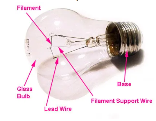
Filament of Incandescent Lamp
Incandescent lamps are now available in a variety of wattages, including 25, 40, 60, 75, 100 and 200 watts. Light bulbs come in a variety of shapes, but basically they are all rounded. There are three main materials used to make filaments for incandescent lamps: carbon, tantalum, and tungsten. Previously, carbon was used as the filament material, but now tungsten is the most used.
The melting point of carbon filament is about 3500oC, and the operating temperature of this filament is about 1800oC, so the possibility of evaporation is considerably low. Due to its carbon filaments, incandescent lamps do not darken due to filament evaporation. Filament lamp darkening occurs when molecules of filament material deposit on the inner wall of a glass sphere as the filament evaporates during operation.
This darkening becomes noticeable over the long life of the lamp. Carbon fiber lamps are not very efficient, which is about 4.5 lumens per watt. I used tantalum for the filament, but it's inefficient, about 2 lumens per watt. This is because tantalum is rarely used as a filament element.
The most widely used filament material today is tungsten due to its high luminous efficiency. When operating at 2000oC, you can give 18 lumens per watt. This efficiency can be up to 30 lumens per watt when operating at 2500oC. High melting point is a major criterion for filament materials, as filament materials need to operate at very high temperatures without evaporating.
Tungsten has a slightly lower melting point than carbon, but tungsten is still the preferred filament material. This is because the luminous efficiency of tungsten is very high due to the high operating temperature. The mechanical strength of the tungsten filament is very high and it can withstand mechanical vibration.
Key takeaways:
CFL and Its Operation
"CFL" is an abbreviation for compact fluorescent lamp. Also called compact fluorescent lamps, energy-saving lights, and compact fluorescent lamps.
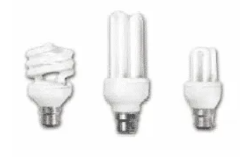
The CFL was initially designed to replace incandescent lamps in terms of compactness and energy efficiency. The basic structure of the CFL consists of a tube that is curved / spiral to fit in the space of an incandescent bulb and a compact electronic ballast at the base of the lamp.
What Compact Fluorescent Lamps (CFLs) Work-Principles of Operation
The CFL uses a vacuum pipe, which is in principle the same as a strip lamp (commonly known as a tube light). There are two barium-treated electrodes on both ends of the tube. The temperature of the cathode is about 900 ° C and it produces an electron beam. This beam is further accelerated by the potential difference between the electrodes.
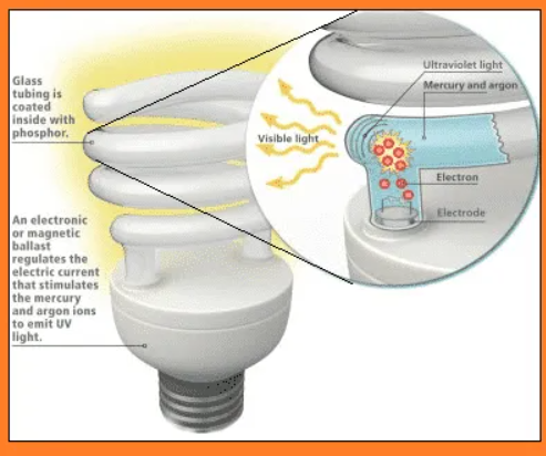
These accelerated electrons collide with mercury and argon atoms, resulting in a cold plasma. This process initiates the emission of mercury in the form of ultraviolet light. The inner surface of the tube contains a "luminophore" that has the ability to convert ultraviolet light into visible light.
This tube is supplied with AC power to facilitate changes in anode and cathode function. The CFL also has a switch mode converter. It works at very high frequencies and acts as a replacement for ballast (choke) and starter assemblies.
CFL Circuit Description
CFL PCBs are extremely compact and fit in a holder base. Compact yet efficiently fulfils your requirements as a choke. The CFL circuit is described in the next paragraph.
Key components of CFL PCB
The CFL PCB contains the following key components:
Circuit description for each phase of the CFL
The operation of the CFL can be broadly divided into two phases. – –
Start Phase
The starter segment consists of Diac, C2, D1 and R6. The components D3, R3, D2, and R1 act as protection circuits, and the rest act as normal operating circuits. You need to remember the following terms:
oD refers to the diode
oR refers to a resistor
o C refers to the capacitor
oQ stands for transistor
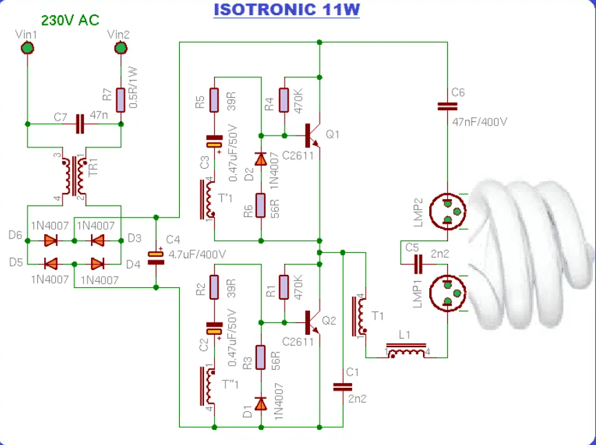
The Diac, C2, and R6 send voltage pulses to the base of the Q2 transistor. This causes the transistor to get the threshold and start working. As soon as the operation starts, the D1 diode blocks the entire section. The capacitor C2 is also discharged each time transistor Q2 operates (after being charged to its maximum value).
Therefore, after the initial start, there is not enough energy left to restart the diac. In addition, the transistor is excited with the help of a TR1 transformer. When the voltage rises from the resonant circuit (L1, TR1, C3, C6), the tube lights up as soon as the resonant voltage is specified by the capacitor C3 (feeding the filament). At this point, the voltage C3 is over 600V.
Normal Phase
Immediately after the ionization of the gas present in the tube, the actual short circuit of capacitor C3 is performed. This will step down the voltage. The C6 then begins driving the changer. The voltage generated by this changer is very small, but it is enough to keep the lamp "on".
Under normal operating conditions, when the transistor is in the OPEN state, the current supplied to TR1 continues to increase until the transformer core saturates, reducing the supply to the base and closing the transistor.
Immediately after this process, the second transistor is excited by the reverse winding of TR1 and the process continues.
Advantages of Compact Fluorescent Lamp (CFL)
The advantages of CFL are: – –
Disadvantages of compact fluorescent lamps (CFL)
LED and its operation:
An LED is a PN junction diode that emits light when current flows in the forward direction. In LEDs, charge carriers are recombined. Electrons from the N side and holes from the P side combine to give energy in the form of heat and light. LEDs are made of a colourless semiconductor material and emit light from the diode junctions.
LEDs are widely used in numeric and alphanumeric segment and dot matrix displays. Multiple LEDs are used to create a single line segment and a single LED is used to create a decimal point.
LED Construction
Charge carrier recombination occurs in the P-type material, which is the surface of the LED. To maximize luminescence, the anode is placed on the edge of the P-shaped material. The cathode is made of a gold film and is usually located at the bottom of the N region. The gold layer on this cathode helps reflect light to the surface.
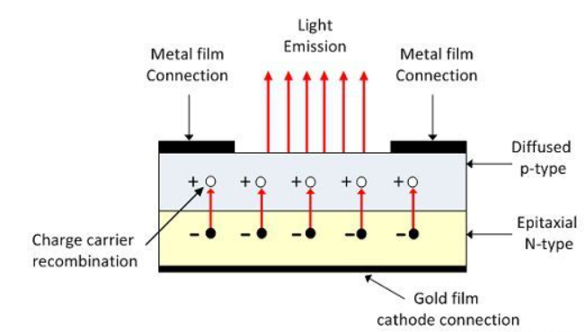
Gallium phosphide is used in the manufacture of LEDs that emit red or yellow light. LEDs are also available in green, amber and red.
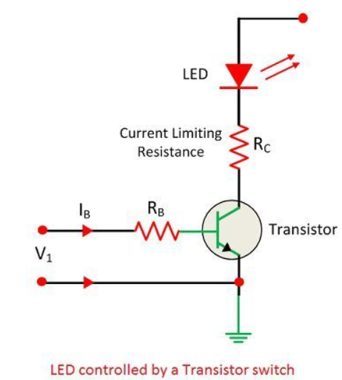
As shown in the figure above, a simple transistor can be used to turn the LED off and on. The base current IB conducts the transistor, and the transistor conducts greatly. The resistor RC limits the LED current.
How the LED works
LED operation depends on quantum theory. According to quantum theory, when the energy of an electron decreases from a high level to a low level, it emits energy in the form of a photon. The energy of the photon is equal to the gap between the higher and lower levels.
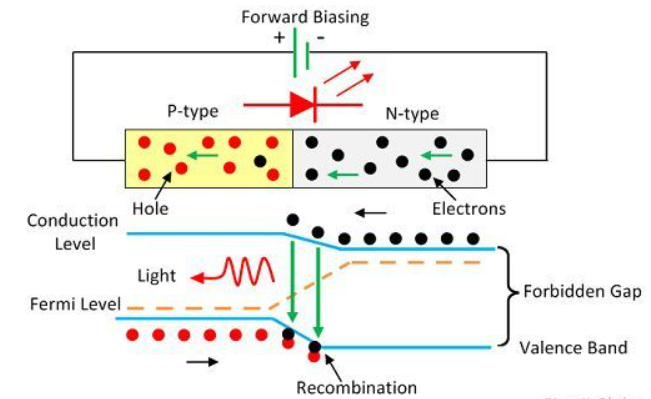
The LEDs are directionally biased and connected so that current can flow in the forward direction. The current flow is due to the movement of electrons in the opposite direction. Rebounding indicates that electrons move from the conduction band to the valence band and emit electromagnetic energy in the form of photons. The energy of the photon is equal to the gap between the valence band and the conduction band.
Benefits of LEDs in Electronic Displays
The following are the main advantages of LEDs for electronic display.
Disadvantages of LED
LEDs consume more power and are more expensive than LCDs. Also, it is not used in the production of large displays.
Key takeaways:
The following are energy-efficient opportunities to cost-effectively reduce energy use.
1. Lighting Control
Automatic control, like an occupancy sensor that turns off the sunshine when space is out there, allows the sunshine to be turned off during non-working hours. you'll also use manual control additionally to automatic control to save lots of additional energy during a smaller area.
The payback period for lighting control systems is usually but two years.
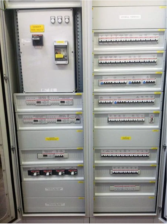
Lighting Control Panel
2. Replace the T-12 tube with a T-8 tube
The industry typically uses T-12 tubes. T-12 refers to diameters in 1/8-inch increments (T-12 means 12/8 inch or 3.8 cm diameter tubes). The initial output of those lights is high, but they also consume high energy.
They (T-12) even have very low efficiency, lamp life, lumen depreciation, and color rendering index. This increases maintenance and energy costs.
Replacing the T-12 lamp with a T-8 lamp doubles the efficiency of the previous and saves power.
T8 fluorescent tube 3d structure
3. Replace the mercury light with a metal halide or high sodium light
When color rendering is vital, metal halide lamps can replace mercury or fluorescent lamps with 50% energy savings. When color rendering isn't important, high sodium lamps offer 50-60% energy savings compared to mercury lamps.
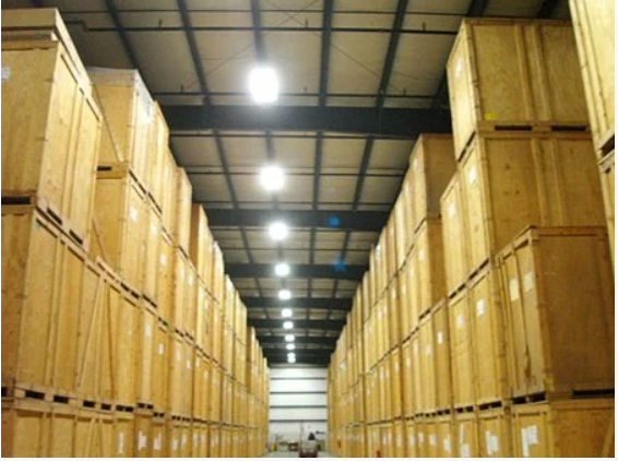
Metal halide lamps applied in industrial and warehouse spaces
4. Replace metal halide (HID) with High-intensity fluorescent lights
Traditional HID lighting can be replaced with high-intensity fluorescent (HIF) lighting. These new systems incorporate high-efficiency fluorescent lamps, electronic ballasts and high-efficacy fixtures that maximize output to the work place.
Advantages to the new system are:
1. They have lower energy consumption,
2. Lower lumen depreciation over the lifetime of the lamp,
3. Better dimming options,
4. Faster start-up,
5. Better color rendition,
6. Higher pupil lumens ratings and less glare.
High-intensity fluorescent systems yield 50% electricity savings over standard HIDs. Dimming controls that are impractical in the HIDs can also save significant amounts of energy. Retrofitted systems cost about $185 per fixture, including installation costs.
In addition to energy savings and better lighting qualities, high-intensity fluorescents can help to reduce maintenance costs.
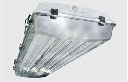
High intensity fluorescent lighting fixture
4. Replace metal halide (HID) with high brightness fluorescent light
Traditional HID lighting is often replaced with high intensity fluorescence (HIF) lighting. These new systems incorporate high-efficiency fluorescent lights, electronic ballasts, and high-efficiency fixtures that maximize output to the workplace.
The advantages of the new system are:
1. Low energy consumption
2. Reduce lumen depreciation over the lifetime of the lamp.
3. Better dimming option,
4. Fast start-up
5. Better color rendering,
6. High evaluation of pupil lumen and low glare.
The high-brightness fluorescence system provides 50% power savings compared to plain HID. Dimming control that's impractical with HID also can save a big amount of energy. the value of the modified system, including installation costs, is approximately $ 185 per fixture.
In addition to energy saving and better lighting quality, high brightness fluorescent lights help reduce maintenance costs.
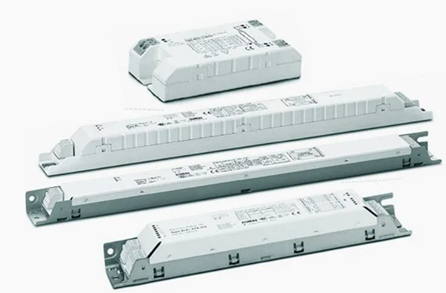
Electronic ballasts for fluorescent lamps
5. Replace the magnetic ballast with an electronic ballast
A ballast may be a mechanism that regulates the quantity of electricity needed to start out a luminaire and maintain a stable light output.
Electronic ballasts save 12-25% on power consumption compared to magnetic ballasts.
6. Optimization of plant lighting (lux optimization)
Production and non-production departments
In many plants, the lighting system isn't specifically designed for the method . There are lux standards for every sort of textile process.
For example, the lux required for weaving is typically above that for wet processing. Even within one manufacturing process, the lux required depends on the method step.
For example, within the cotton spinning process, the lux required within the blowroom should be much less than the lux within the ring frame section. If the lighting provided is above standard (lux required) in any a part of production, this results in wasted power.
Therefore, plant engineers got to optimize their lighting systems supported standard lux specific to every process step.
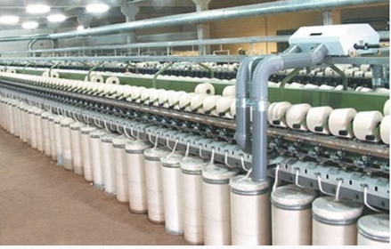
Cotton spinning production line of clothing manufacturer in Bangladesh
7. Optimal use of natural light
Many plants don't use natural light to the optimum level. Additionally, to optimizing the dimensions of the windows, transparent sheets are often installed on the roof to permit more sunlight to penetrate the assembly area.
This can reduce the necessity for daytime lighting.
Key takeaways:
The lighting scheme should be as follows:
The following factors should be considered when designing a lighting scheme:
Factor # 1. Lighting level:
This is the most important factor. Sufficient lighting is the basic means of seeing the surroundings, and unless it is a light source by itself, the object will only have the required brightness when it is illuminated. It is the job of lighting to give objects distributed brightness. Body color has the property of reflecting light to varying degrees. It is this difference in brightness that gives the essential perception of detail. Each type of work has a range of brightness that best suits the output. This means minimizing fatigue and providing maximum output in terms of quality and quantity.
The degree of illumination to give an object the required brightness depends on:
(I) Size of the object seen and distance from the observer-The greater the distance of the object from the observer and the smaller the size of the object, the greater the lighting required for its proper perception.
(II) Object and background contrast-The greater the contrast between an object's color and its background, the more lighting is needed to properly distinguish the object. Objects that are seen for long periods of time require more lighting than casual work. Similarly, moving objects require more lighting than stationary objects.
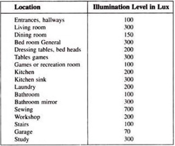
Illumination level required, as per ISI, in various parts of a building is given below:
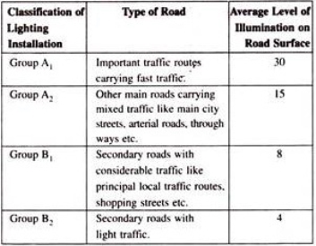
Illumination level required, as per ISI, for various types of traffic routes is given below:
Factor # 2. Lighting Uniformity:
The human eye automatically adjusts to the brightness in the field of view. Lack of uniformity can lead to eye fatigue and reduced productivity due to the need to adjust the pupils and iris of the eye more often. Best visual performance has been found when the range of brightness in the field of view is 3: 1 or less, which can be achieved by using general lighting in addition to local lighting.
Aside from considering fatigue, local lighting, which does not use anything that matches general lighting, creates a psychological sensation of loneliness, darkness, and unkindness. Therefore, the modern trend is towards the adoption of "local and general lighting" and "general lighting directed to the work surface", especially in mass production factories, offices, drafting offices, stores and the like.
Factor # 3. Light Color:
The appearance of the body color is completely dependent on the color of the incident light. In general, the composition of light should make the colors look natural. In other words, the appearance of artificial light should not be much different from the appearance of daylight. Today's daylight fluorescent lamps allow you to economically illuminate large spaces with artificial daylight, providing excellent color rendering and a sufficiently high level. For certain applications, such as street lights, if you don't need to distinguish different components by color, the color of the light is less important and you can use a highly efficient discharge lamp that causes color distortion.
Factor # 4. Shadow:
In luminaires, the formation of long, hard shadows is considered a drawback as it causes eye fatigue. The complete absence of shadows does not necessarily mean the ideal condition of the luminaire. Perhaps contrary to public opinion, some shadow is desirable for artificial lighting. The purpose is to give shape to solid objects so that they can be easily recognized. Objects illuminated by shadowless light are flat and uninteresting, lose their contours, and make it difficult for the eyes to correctly determine the shape of the object. However, there is one exception to this. In other words, shadowless light is essential in a drawing office that looks at a flat surface. Otherwise, the shadows will get in the way of your work.
Hard and long shadows can be avoided in the following ways:
(I) Using a large number of small luminaires mounted at a height of 2.5 meters or more,
(II) Use gloves on filament lamps or use indirect lighting systems to use wide surface light sources.
Factor # 5. Glare:
It may be direct or reflective. That is, it may come directly from the light source, or it may be the brightness reflected from a desktop, nickel-plated mechanical parts, calendar paper, etc.
Direct glare from a light source is more common and often interferes with vision. A glance at the sun reveals that a very bright light source causes acute eye discomfort. Light sources that are much less bright than the sun, such as incandescent filaments and gas lamp incandescent mantles, also cause disco.
Mfort by direct glare. Reflective glare is glare that is visible as a glint or reflection of a light source on a polished surface.
A bright light source near the middle is acceptable by placing it at a height above normal field of view.
Metal reflectors for industrial lighting usually have a skirt around the edge of the reflector.
Factor # 6. Mounting Height:
The mounting height is largely determined by the type of building and the type of lighting scheme used. In direct sunlight, in rooms with large floor areas, the luminaire should be installed as close to the ceiling as possible. Lowering them not only reduces the uniformity of lighting, but also increases the glare in the field of view without significantly increasing utilization. In the rare cases of small rooms with high ceilings, there are things that can be gained by lowering the luminaires, but again, using filament lamps with focusing reflectors and mounting them high may be a better solution.
In the case of indirect and semi-indirect lighting, of course, it would be desirable to hang the luminaire well below the ceiling in order to provide reasonably uniform lighting to the ceiling. In practice, this is usually interpreted to mean that the length of the suspension tube should be one-fourth to one-third of the horizontal spacing between rows of luminaires.
Unfortunately, it is very commonly recognized that a minimum clearance of 2.5 meters between the luminaire and the floor is required, so it is often impossible to hang them so far. Therefore, in a room with a low ceiling, uneven ceiling lighting is inevitable. This is fine as the ceiling is not a working surface.
Factor # 7. Luminescent Spacing:
Accurate placement is very important to provide uniform illumination over the entire area and therefore eliminates the relatively dark areas that are often seen with poor fitting spacing.
In direct and semi-direct luminaire situations, the proportion of horizontal spacing between rows from the work surface to the luminaire height depends to a large extent on the luminaire's candle power distribution curve. For fluorescent lights, it is recommended to set the value of this ratio to 1 and the upper limit to 3/4. For tungsten lamps in combination with focusing reflectors, the ratio of spacing to height should be approximately 0.6.
For indirect and semi-indirect luminaires, it is advisable to aim for a horizontal spacing between rows that is approximately equal to the height of the ceiling above the work surface. The horizontal spacing should not exceed 1.5 times this height.
For fluorescent emitters, it is common practice to combine two or more emitters end-to-end so that they share a common outlet. In fact, continuous rows of luminaires often work, especially if the specified lighting is quite high.
Factor # 8. Surrounding wall color:
The lighting in any room depends on the light reflected from the walls and ceiling. White walls and ceilings reflect lighter than colored ones.
Key takeaways:
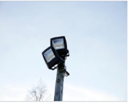
Floodlight may be a wide selection of beams and high-intensity artificial light. Frequently won’t to illuminate an outside stadium during an outside gaming event within the dark. More careful classes are often used as stage lights for live presentations like concerts and plays.
At the highest of the many professional sports, it's a prerequisite to possess floodlights on the pitch in order that the game are often planned during outdoor daytime hours. Sunset and night contests may evoke viewers who have made work or other appointments before the day and enable television broadcasts during lucrative golden time hours. Some sports lands that don't have durable floodlights may use temporary, portable floodlights instead. Many large floodlights have a framework for bulb shifting and maintenance.
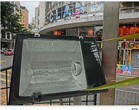
Metal Halide Floodlight
The most common sort of floodlight may be a metal halide lamp that emits bright white light (typically 75-100 lumens / watt). Sodium lamps also are common in sporting events as they need a really high lumen to watt ratio (typically 80-140 lumens / watt) and are a price effective option when a specific lux level must be provided.
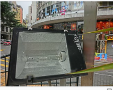
LED Floodlights
Halogen Floodlight
LED floodlights are bright enough to be used for lighting purposes in vast arcades. The most important advantages of LEDs during this application are low power consumption, long life and fast start-up. Many metal halide floodlights are being replaced. Halogen and electrodeless inductive floodlights also exist.
Key takeaways:
References:


