Unit - 4
Industrial Electrical systems I
HT-high tension or high tension, where there is a very high voltage is used in the low power mode of the plasma is generated. The High-voltage unit and a HT application to the wholesale buyers of electricity, which is needed for 11 kV and above. The HT is applied to the wholesale buyers of electric power and industrial enterprises (large industries), major corporate offices, schools, dormitories, and even residential colonies (as in the micro districts that buy at the wholesale price). The rates of most of the state-owned distribution companies have been different between LT and HT.
HT-Connect Features:
1. Rating
LT cables give to a normal voltage, below, 1100V, while the HT cables on 3300V.
2. Guides
Aluminium and copper are the most commonly used conductors for the LT and HT cables.
3. Insulation
Both the LT and HT cables, a layer of insulation to protect the cable from external interference. TV-wires-to-use materials, such as PVC, while the HT wires, usually of cross-linked polyethylene (XLPE).
4. Armor
Armor is a protective covering for cables, such as the LT and HT cables. However, some of the L. the cables can be an unarmored.
5. Number of cores
L the cables are made up of 1 or 2 more cores, however, they can develop up to 61 cores, while the HT cables consist of copper or aluminium stranded in the nucleus. As a rule, they are either 1 or 3 cores.
6. Application
L cables are mainly used in industries such as power generation, power distribution and railway, subject to a maximum of 1100W. HT cables, on the other hand, are most often used for the distribution or transmission of electricity in excess of 1100 watts of power.
7.HT Electricity Rates
The distribution companies to provide electricity at different rates for different categories of consumers, it is the most common categories are: residential, industrial, and commercial. The prices are the lowest are for residential use, and are the highest for the industry.
Types of electricity tariffs:
A. the Domestic rates
The team in diameter, consists mainly of a mass or services in the local community. In most cases, the tax is generally divided into categories, as a commercial property, can be placed in the same building, and offers an opportunity to grow when the stakes are high.
B. Commercial and industrial costs
The structure of the industrial and commercial tariffs can be completely different compared to the national norms and standards. Although the cost of the generation and distribution of electricity is the same, and that the fees charged to the recipients, and can be different from each other. For example, if the average price of a service, it is $ 0.10 per unit, this is an internal user is able to pay $0.08 per unit, while the industrial, the user may have to pay $0.15 per unit. In this case, we can say that the domestic consumer to receive a cross-subsidies from industrial to consumer. Such a grant, the relationships can be implemented in order to ensure that the average person would not be responsible for the increase of the energy costs.
The HT line to Increase the effect:
HT-line growth, it may help to reduce both the voltage drop and line losses. Check out these two points, and more.
Very low voltage drops
The voltage drops in the L of the cables, because the lines are long and have a small wire size. In the HT power distribution systems, the voltage drop on the distribution of power is likely to be less than 1%, compared with that in low-voltage systems. This makes for a great stress for the average consumer.
Loss reduction
Get the low-voltage wires in a power distribution system, the engine is at a low voltage may lead to a higher line loss. The rule, however, the losses in the high-voltage system, and the distribution of an equivalent amount of energy is far less than 1% of that of the whole of the NN system. Therefore, in the battery pack from the power distribution system, the total energy loss is significantly lower.
Because of all of these factors, such as the capacity factor and the power factor will remain the same, the proportion of the losses in a system with a high L/HT ratio was generally higher than that of a distribution system with a lower-LT/HT ratio.
In a power distribution system, it is more than just a pair of wires for the transmission of electrical energy. It is comprised of cables that both the high and the low power supply voltage. The cables are the most important part of the entire electrical power distribution system, as they are.
Key takeaways:
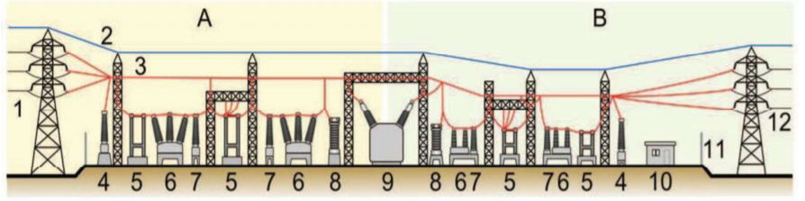
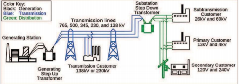
A train station is arranged between the battery, transmission, and distribution to the consumer, including the connection of generators, transmission lines or distribution of the load to the other, and a reduction of the high voltage on the low, in accordance with the specific requirements of our customers. For example, we do not use electricity directly from an 11 kV power line, or to a 33 kV transmission line. In order to make use of the energy of these lines, then, we may be required to receive the energy through a transformer from these lines. Therefore, you need to install the drive. In addition, if we want to transmit electrical energy over long distances, then we also need to install it on a drive to provide a high voltage for transmission. The station is also an important factor in the management of energy, that is, the change in the frequency of the conversion of alternating current to direct current or the reverse of a direct current to an alternating current, to connect the various power lines and electrical wiring, and so on. A train station can be as simple as a single transformer for our houses, and villages, or of a plant, and as much as several power transformers, transformers, and workers, as well as the CTS, PTs, breakers, isolators, bus bars, lp, LT panel , HT panel, PFI plant, AVS, IVS, ATS , HT cable, LT cable, MDB, executive, SDB board, IPS, and other small-and heavy-duty electrical devices to a single property. But both of these can be referred to as stations.
Train Station: The Key, the key to power lines, B: Edge of the secondary power lines
1. - Source high-voltage power lines
2. Earth wire
3. Power lines
4. The transformer for measurement of electric voltage
5. Turn the power switch to the
6. Automatic circuit breaker
7. Current transformer
8. Lightning rod
9. Main power transformer
10. Control building
11. Protective cover
12. Secondary power lines
Thus, it is an integral part of the power system. The continuity of the power supply, and depends only on the motion. Therefore, it is to the design and implementation of the station to the right place, special care needs to be taken. Some of the points are as follows: The drive will need to be able to be easily maintained and repaired. This location must be suitable for the installation of the drive. It should not be installed in the center of the load. The drive must have a sufficient number of protective devices, or personal protective equipment. There should not be plenty of opportunities to start out with the cleaning and the maintenance. In addition, there is a fire protection system is to be installed. The system needs to be reliable. In the design phase, it is necessary to take into account the protection of the gears and other mobile devices. In the process, it was well maintained, therefore, to ensure reliable operation. The investment should be kept as low as possible.
Types of sub-stations
1. Channel
2. Drive panel
3. Collector, railway station
4. The variable sub-stations
5. The external drive is
1. Channel
A vector is a combination of two or more electric circuits. In the simplest case, when all power lines have the same voltage. Receiving channels, which can vary from the simple to the complex. In such cases, the drive that contains high-voltage switches that allow you to connect or isolate the rules of troubleshooting and maintenance. The channel can have transformers to convert between two transmission voltages, voltage control/power factor correction devices such as solid-state capacitors, inductors, or static VAR compensators and equipment such as phase shifting transformers to control the flow of power between two adjacent power systems. The largest of the receiving stations may have a large area with different voltage levels, many circuit breakers. Today, it is the voltage at the transmission level, it is generally considered to be 110 kV and above. Lower voltages, such as 66 kV and 33 kv, are usually considered sub-transmission voltages but are occasionally used on long lines with low property taxes. Voltages above 765 kV are considered to be at high voltage and require different design compared to the equipment that is used at a lower voltage.
2. Drive Panel
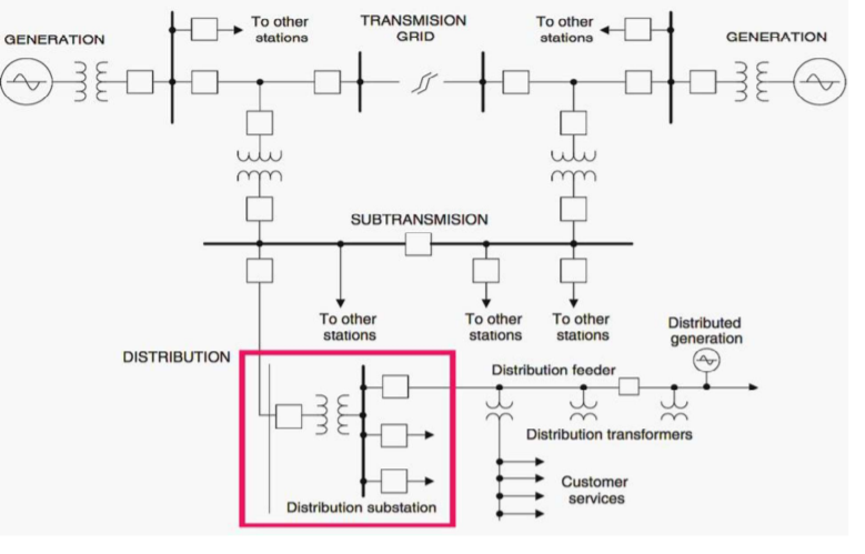
The distribution of drive, send the power of the system is old, the district's distribution system. The use of distribution of the input consists of at least two high-voltage power lines or sub transmissions. The input voltage may be, for example, 115 kV, or something that often happens in the field. The output is a row of enemies. The distribution of the station operates normally, at the medium-voltage levels, from 2.4 kV to 33 sq. m. The charge walking the streets overhead (or underground, in some cases, the distribution of the voltage transformers are used, the location of the customer, or in their immediate vicinity. In addition to voltage conversion, substation switches can also be the cause of the error in transmission and distribution systems. These connectors are usually of voltage adjustment points, but in the long distribution circuits (a few kilometers away), output voltage adjustment, the equipment can also be installed along the line. In the central areas of large cities and towns, with complex switches in a high-ec) stations, as well as the switch, and the other systems on the low-voltage side. A distribution station is a combination of a switch, the control and reduction of stress on equipment, which is designed for the reduction of the sub-transmission voltage of the input power for residential, agricultural, commercial, and industrial loads.
3. The variable sub-stations
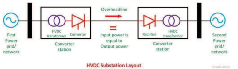
Electric-equipment and machines that run on a direct voltage of the property for industrial use. Ac drive converts the electrical energy in alternating current (ac) and direct current from the transmission of electricity. These are the stations that can be connected to a high-voltage direct current (HVDC converter plants, caused by an electric current, or interconnected non-synchronous networks. These stations are equipped with a powerful electronic device to change the frequency of the current, as well as for the conversion from ac to dc (or vice versa). Direct current, or HVDC (high voltage direct current lines are to be used for the exchange of data between the countries have been at the transmission network level. In dc transmission lines, the variable sub-stations can be used to convert three-phase ac to dc (rectification) at the sending end of the line, and the ranges of the inverse conversion (inversion) at the other end of the line. These stations are located on either side of the power line. In some cases, these stations are situated in the generation of power plants to the transmission of electric power. Two unsynchronized AC transmission systems can be connected together with the converter stations. Floating drives are also available at most of the stations, the emergency back-up power system, in order to convert it into alternating current for use in the event of an emergency. The different levels of the design, the cost for a HVDC system, the power transmission capacity ranging from 200 kW to 600 MW. The different types of variables used in the DC-to-end.
4. Collector, Railway Station
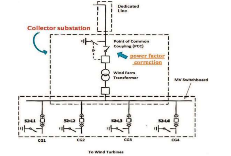
In order for a solar power plant, a fan of farm or of a hydro-electric power plants, you need to be a collector, a kiosk-type to compatible with all the generators and connect them to the power supply. This is similar to a ground station, while the energy flow is in the opposite direction to the direction of wind turbines and solar up to the transmission system. As a rule, to save the building, and the collector system operates around 35 kV, and the collector station to increase the voltage to the output voltage of the issues in the network. For the collector, the station can also be power factor corrected, if necessary, the measurement and management of the wind farm. In some special cases, it may be for the collector, the station can also be an HVDC converter station. Substation and collectors, are available for the different thermal or hydroelectric power plants of similar capacity, are located in the surrounding area. The collector system is made up of many elements. High voltage power transformer, wire, subway or plane), sensors (current, voltage, thermal, and magnetic), and the lightning protection system, earthing switches and switches to the video-surveillance system, etc., etc.
5. The external drive is
The Diameter of a substation without using a transformer, which will only work on the levels. Switching stations are sometimes used as collector and distribution stations. Some of them can be used to turn off the current to the extra phone lines or parallelize the circuit in the event of an accident. Diameter of the drives may also be known as the instrument of the train stations, and they are usually located next to or in the vicinity of the power plant. In this case, the generators of the power plant, they get their energy from the inner courtyard, to the generator, a wheel at one end of the yard, and the transmission lines they get their energy from a substance, on the other side of the court. An important function of a substation is switching, i.e., the connecting and disconnecting of wires or other components of the system between on and off. Unexpected changes may be caused by a fault in a power line, or to another program, for example, the line has been struck by lightning, and an arc is developed, and the structure is supported by a strong wind. The main function of the station is a combination of switch is to isolate the faulty part of the system in the shortest amount of time possible. The energy of defective equipment to protect against damage, and the ability to isolate the fault, it helps in maintaining a steady operation of the rest of the network. In this classification, the Drives can be classified in a variety of ways, including the following:
1. The format is dependent on the stress level
A. S. use: united nations (33 kW (66 hp), ultra (132 kV to 400 kV) ultra-high-vacuum (400 kV), and the MV/ control station/public use (2 kv to 33 kW). N./individual station, 220, and 440 V DC, high-voltage substation.
2. Classification by structural features
This hotel is located in the open air at the rated voltage up to the 66 kW). Indoor stations in the building of the nominal voltage of more than 11 kW). The mine are here, with special attention to the design due to the additional protective measures are necessary during the operation of the power plant. Temporary need for a Mobile station. Polar stations, of a diameter of drive equipment to be installed overhead, the N in the middle of 4 in the mid-to structure.
3. Classification on the basis of the configuration
A # a Conventional air-insulated power Station (up to 800 kV) GIS, SF6 Gas-insulated Substation (GIS), a Compound of This type, motion is a combination of the two above-mentioned
4. The application on the basis of the classification
Turn on the power transformer to be associated with the generating station, such as the generation of the voltage is too low. The main network will drive the desired load, center, along with the main product. Steps down to 66 kV to 220 kV), and the second drive on a secondary power line, the step-down of up to 11 kW). A distribution substation where the mains voltage drops in the power supply. Mass delivery, and in industrial drive, Similar to the distribution of the station, but they are made individually for each and every consumer. 11 kv is delivered to a ground station
5. Classification according to the type of service
The power factor of the station is that it improves the system, the power factor by the use of synchronous condensers. Row station, radio stations, which is the frequency in Industrial drive, that drive, that is, the supply of electricity to industry.
The choice of a Power Transformer
A guide to the understanding of how to determine the size of a single-phase or three-phase power transformer.
Single-Phase
A single-phase transformer is designed to convert a single-phase or three-phase input connection (source) voltage to a single phase-to-phase voltage stress voltage, which is required to run the equipment. Click to select a suitable single-phase transformer is, you need to determine:
(1) The equipment that is being powered by a single power supply (see rating plate or in the installation guide).
(2) The primary voltage of the transformer. This is the same as that of the line (or the original), voltage, typically by 480 or 600 vac.
3) the Secondary voltage of the transformer. The equipment has been installed, you have to have a certain power supply voltage (refer to the unit rating plate or in the installation guide). The selected transformer must have a secondary voltage is equal to the power supply of the equipment, usually 120/240 v AC.
(4) The frequency in Hertz (hz, cycles per second) of the input (source) voltage must correspond to the frequency of the supply system. The selected transformer must operate at the same frequency. The typical frequency is 60 Hz.
5) the amount of the liability, the tax is determined by the product of the voltage applied to the load and the current through it. It is usually expressed in VA (Volt-Amperes or kVA (kilovolt-Amps) on the unit's rating plate. The total stress is often a combination of various loads (lights, radiators, and engines). You need to have the calculation of the individual loads and put them together to get the total load on the transformer. The selected transformer must have a maximum rated capacity of the batteries, which is equal to or greater than the load on the transformer.
Three-phase-to-phase
The three-phase transformer is designed to convert three-phase-to-phase input (source) voltage is single-phase-to-phase and three-phase-to-phase voltage stress at the voltage required by the system.
In order to select an appropriate three-phase transformer, you will need to provide:
The total stress is often a combination of various loads (lights, radiators, and engines). You need to have the calculation of the individual loads and put them together to get the total load on the transformer.
The selected transformer must have a maximum rated capacity of the batteries, which is equal to or greater than the required load. Note: The three phase transformer must be selected so that any one phase is not overloaded. If you are connecting a single-phase load to one phase of the three-phase transformer, you must calculate the load as if it were loading all three phases.
An industrial load is out of the question for the press on a variety of industries. It includes all of the electrical equipment is to be used in the industry, as well as the equipment used. Industrial load may be connected to the whole of the day. Industrial loads, and have a steady demand, and are considered to be the most important income tax. Commercial tax is not a lot of seasonal fluctuations and adverse weather conditions. The load duration curve is shown in the figure below. These costs consist mainly of industrial equipment such as motor, ovens, furnaces, batteries, industrial lighting, hardware, lifts, and pumps. Industrial loads that consume more electricity is provided by the service to the community. This tax will not be changed during the low season, with a continued demand for the dag. De industrial load consists of the industries, small, medium, large, heavy, and handcrafted in production. An induction motor that generates the majority of the composite load. An industrial load, and the load. The full load is a function of the frequency and the voltage, the greater part of the load on the system.
The different types of tax, for use in industrial applications
The three different types of industrial loads, which are the engines have to work on, as shown below:
(i) continuous load
(ii) intermittent load, and
(iii) a Variable, or variable costs.
The engine's power is dependent on two factors. First of all, it depends on the increase of the temperature, which, in turn, will depend on the question whether or not the motor is designed for continuous use in the repeated and short-term or a variable load. Second, it will depend on the maximum torque that a motor will develop. Having regard to the requirements established by the time of the load, the motor rating is determined by the load conditions, as explained below.
(i) a Constant Load.
In such cases, the calculation of the capacity, it is much easier, as the consumer, such as pumps and fans, which require a constant power to run. However, it is important for the calculation of the motor voltage is correct. When the motor is less than required, the engine is overheating, and as a result, the situation is going to occur. If, on the other hand, the estimated HP is more than just what is necessary for it to load, then the engine is cold, it will run at a lower efficiency, and power.
(ii) the Taxes are to be Filled in. Such a tax could be one of the following formats:
(a) in cases Where this type of load is applied to the motor for a short period of time, and then turns off for a long enough period of time, allowing the motor to cool down to room temperature, as shown in the figure below. 45.2. In such a case, the motor with a short-term heating, as in a kitchen to mix
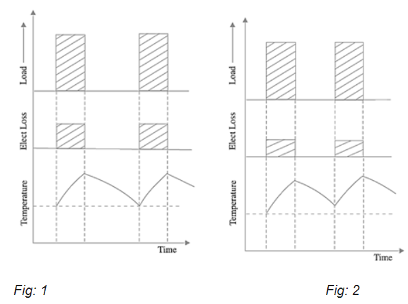
(b) in the case of the type of the load, restart the engine for a short period of time and then shut off for a short period of time. The conclusion of the period of time is too short for the engine to cool down to room temperature, as shown in the figure.2. In such cases, it is the right-continuous or intermittent rated current of the motor is selected, that is, during the operation of on-load period will not exceed a specified temperature is to be reduced.
(iii) Variable Cost. In the event of such a tax, to be the most accurate method for selecting a suitable motor and to plot the heating and cooling curves according to the load variations for many of the engines. In order to do this, select the smallest engine size that is not greater than the allowable increase of the temperature during the operation to a specific load cycle.
However, it is a simpler, but still quite accurate method for the selection of the appropriate motor output is to assume that the heating is proportional to the square of the current, and therefore to the square of the load. Its continuous power rating of the engine will be equal to the nominal current of the motor.
Motors
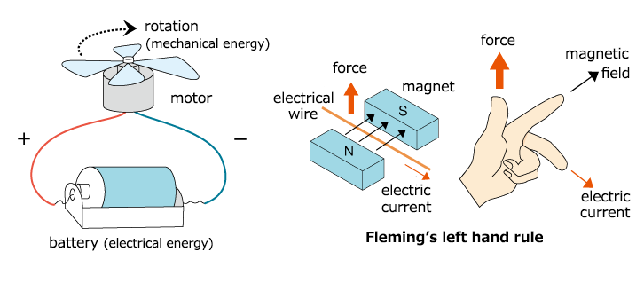
"it's a machine that converts electrical energy into mechanical energy." In other words, the amount of electrical energy is a power source, and the mechanical energy is not a "turn"." In order to explain this is that the motor is physically, well-known as "the Fleming's left-hand rule". When an electric current flow through an electrical cable is located between the two magnets are facing each other, and it creates a power. Electric current, magnetic field, and motion, respectively, are applied normal to the direction of each other, in the same way as for the opening of the middle finger (the electric current), and the index finger (the magnetic field) and the fingers ("power"), and the left and right hand, respectively, at right angles to each other axes.
What causes an electric current, through an electrical wire to create a effect? It was as if an electric current, through an electrical wire, it creates a magnetic field around it. The magnetic field attracts or repels the magnetic field of the magnets, which will make the troops to move on to the electric cable. Electricity is here, "the electrical voltage and mechanical force"."
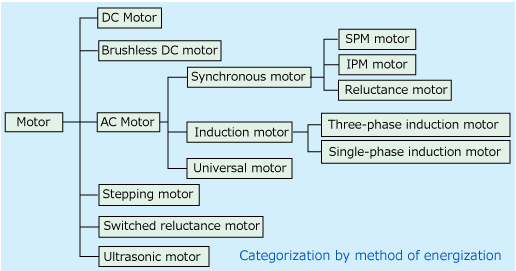
Layout Engine
The DC motors to pass direct current (DC) in the next, an AC electric motors to pass an alternating current. A brushless DC motor is a DC motor, which has been replaced by a broom and a switch, a solid-state switch control. The universal motor is able to crank the engine at a high rpm of an AC electrical power, 100V, households, while at the same cloth, and a collection of DC motors. In addition to this, a stepper motor, which moves in a rectangular flow, and a non-uniform jet engine. An ultrasonic motor is a special motor that works by the vibration, piezoelectric ceramic, the frequency of the power supply.
1) for DC motors
To the engine in that many of the Japanese students who are in their experiments, when they were in elementary school it was one of DC motor. It is the most widely used engine, used in the models, as well as electronics, and vibration motors for cell phones. About to explain the structure of the motor has a rotor and a stator. The rotor is the part connected to the shaft, and the stator is the fixed part, which contains the outer part of it.
The stator of the DC motors with permanent magnets, and brushes that supply power to the rotor, and the rotor provides the windings, and an on-off switch. As soon as the brush is applied to the dc power to the switch current starts to flow through the winding connected to the switch, and it creates a disconnect. Here it is, the wires and the switch will have a mechanism in place to the flow of electric current in such a way that the torque remains at the same level. The biggest feature of the DC motor with the ease-of-use with a dry element. You can use it to change the direction of rotation by simply changing the connection of the wire leads. Therefore, the DC motors are used on a large scale.
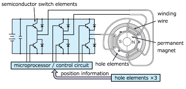
2) brushless DC motors
You can find the description of a brushless DC motor, "as a motor without any brush, even though it has a function similar to that of a DC motor." It keeps track of the stator windings and the magnets in the rotor structure. It's not that the brushes and the commutator, which was previously a DC-motor is in place, which is a solid-state switching element is on the outside of the engine. It works as a constant DC voltage by at least two of the three phases U, V and W-phase windings. He turns on the power, according to the position of the permanent magnet is defined by, for example, an element, a Hall sensor, and it continues to generate the same level of torque.
3) Synchronous motors
On the other hand, it is a synchronous motor operates in a condition of use of the information provided by the sensor is attached at the edge of the rotor. The electric motor has been named to the mechanism by which the rotation of the earth's magnetic field is generated by the three phase-to-phase voltage winding is in sync with the rotation of the rotor. The structure of the synchronous motors, which is basically the same as that of a brushless DC motor. Therefore, people often mistake synchronous motors with brushless DC motors, and vice-versa.
One of the characteristics of both the synchronous motors and brushless DC motors is that they are able to do to avoid brush wear and electrical noise. They are also capable of size reduction, high performance and high productivity through the use of powerful rare earth magnets. Thanks to this feature, there is a wide range of applications, such as appliances, consumer electronics, automobile, and motors and drives. It is said to be that of DC motors have some 70% of the total number of brushless DC motors and synchronous motors, and is responsible for about 20% of the total volume, are produced in small engines.
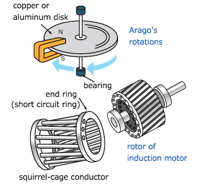
4) Induction motors
This is the principle of rotation of induction motors is based on the "Arago rotation", was discovered by the French physicist Arago. This is the phenomenon that after the installation of the aluminium disc is in between the U-shaped magnet, and then slide the magnet in the direction of the rotation of the aluminium disc starts to rotate in the same direction, with a slight delay. When the magnetic field is in the stop magnet, the changes in the aluminium, the board of directors, and a coil of electric current through the aluminium disc (the law of electromagnetic induction (emi), and the action of electric and magnetic field, and the U-shaped magnet that generates electromagnetic waves. Induction motors have been the invention, which is used Arago spins.
The stator of the induction motors has three winding phases in the structure. The rotor includes an aluminium part, in the shape of a house (tutorial is in the form of a case). If you have a run in with the three-phase windings of a sine wave, it creates a magnetic field which rotates at a frequency of. Then, in Arago's rotation principle of the electric current that flows through a closed conductor, who will receive changes in the magnetic field and the rotor begins to rotate with a small delay.
Induction motors are less efficient compared to brushless DC motors and synchronous motors which use permanent magnets, but there are also other features, such as the one used for the three phase-to-phase voltage of the commercial AC power supply, 200 V, can be run without a Hall sensor, the angle of the sensor element, which is difficult to break down, you may be able to work efficiently with the AC drive, as well as be able to provide high power with a great engine. There are plenty of opportunities for the use of induction motors in industrial environments and cars. Just as biological diversity (cbd), we have a lot of motors for a wide variety of a type, depending on the differences in the structures and distribution of this material.
How to start the engine
The majority of large induction motors are running it down the line, but when very large motors are carried out in such a way, they cause a voltage disturbance of power lines by leaps and bounds in the inrush current. To limit the travel of the inrush current, larger motors are started at a lower voltage and then connected to a full-Instagram voltage on the run from the close of rotational speed. Two ways to get started with a low-voltage, star-shaped delta starting and auto transformer starting. Magnetic switches perform switching operations in the start-up, connect and disconnect the motor to the power source. If the current exceeds the rated current of the motor, the contactor will automatically switch off to disconnect the motor from the power supply. Three-phase-to-phase voltage in the stator of a three phase induction motor, which, in turn, creates a magnetic field that rotates in the stator. If the magnetic poles are rotating, the speed of the rotating magnetic field which determines the
N = 120 f /P
From The Principal:
A high inrush current, it will cause a large voltage drop and will affect the operation of other devices. It is not recommended to run large motors, directly in the field with reference to the total voltage of the motor). As a rule, with engines with a capacity of no more than 5 miles to the start. To reduce the inrush current, reducing stress on the stator or the rotor, in particular for induction motors with a locked rotor. Full power is used only when the motor picks up speed.
The methods for starting an induction motor are:
1. Direct Online Starter
It's an easy and cheap-the starter for 3-phase induction motor.
The contacts are to be closed against the action of the spring bloom. This method is generally limited to a smaller cage induction motors, because of the inrush current can be up to eight times the motor full-load. The use of a two-cell to the rotor and reducing power (around four times, and the use of a high-speed ac that you can use to start engine with a power output of 75 kW and higher, in real-time. An isolator is required for the insulation of the cable, the power supply of the service. The motor must be protected. A few of the protective measures that are in over current protection, under-voltage protection, short circuit protection, etc., etc. The tension in a time loop, drops by the auto-transformer.
2. Star-delta starter
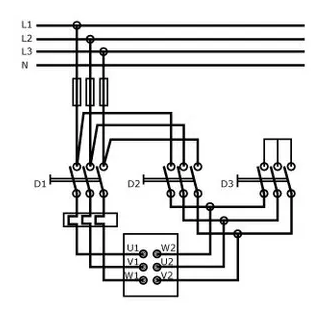
A three-phase motor, it produces three times as much power, if the stator windings are connected in delta when it is connected to the stars, but it will also be 1 / 3rd of the power from the power supply when it is connected to the star than that, when combined, are in the delta. The start time by a star, it is equal to it? from the beginning, in the delta.
1. A two-position switch (manual or automatic) is provided by a time relay.
2. Carried out in a star, it reduces the inrush current.
3. When the engine is accelerated to the speed and the current is decreased to the normal range, the start-up going into the operating position, with the windings connected in delta.
4. The more DOWN-starter, star-delta starter, the motor with sufficient torque to be able to start up at full load, so the output is to be reduced, in the first place. Therefore, the engines are usually started at a low load.
5. Turn, caused a transient current peak value are higher than those of the LOW -
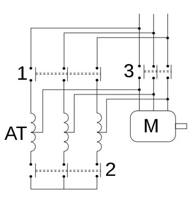
3. Automatic Restart of the Engine is in Production
1. Controlled by a wall switch with two modes of operation, i.e., manually / automatically, with the aid of a countdown timer in order to move from the home position to the start position.
2. In the first position, the power is connected to the rotor windings through an auto-transformer, which is the applied voltage, 50's, 60's, and 70% of the nominal value, depending on which of the tap being used.
3. Reducing the voltage reduces the current in the motor windings, with a 50 per cent at the tap output signal is used, it is cut in half, and the power will be half of the output current. Therefore, the inrush current of the power supply, it will only have 25% of the current is taken from the starter.
4. For an induction motor, the torque, T, is being developed at V2, and up to 50% of the clicks, the start-up torque (0.5 V) 2, is obtained from the start of a DOWN. Thus, 25% of the torque can be obtained.
5. Start-up firms in the automotive industry is larger and more expensive.
6. The switch to the position, in effect, caused a transient voltage that may be greater than the value obtained at the start of a
DOWN.
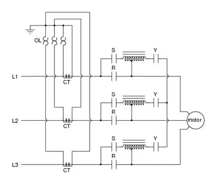
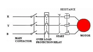
Rotor Resistance Starter
1. This is an appetizer that is used by the motor is on the ball. It makes use of the external resistance / phase in the rotor circuit so that the rotor will be the development of a high-value pair.
2. A high torque is generated at a very low speed, when the external resistance is high.
3. During the start-up time, power is connected to the rotor through a three-pole contactor, and at the same time, add an external resistance in the rotor.
4. The high resistance limits the current flow and allows the engine to start safely under high load conditions.
5. The resistors are usually of wire, type, and are connected by the carbon brushes and slip rings are used for each phase of the rotor. They are filled with items that have to be displayed on an on-going of the contactor base.
6. After the engine is started, the external resistance in the rotor is continuously removed from the circuit in the handle, or the starter is running, and it moves to three contacts at the same time from one contact to the other.
7. The three movable contacts are connected to each other, forming the basis for the resistance.
8. In order to ensure that the engine cannot be started until the resistance of the rotor is in the house, a lock is installed, which prevents the contactors from closing until this condition has been met.
The One-Line Diagram
Each demanding power, even if it's in a three-phase circuit can be represented by a line graph, in which the various elements of the electric grid, and in their relationships. In single-line mode, sub-stations, such as the transformer, the incoming and outgoing of lines, bushings, gear, and equipment are being represented by the use of symbols, and their inter-relationships between them are shown by lines. Single line diagrams are useful for the planning of the station layout. A number of symbols that can be used to indicate a railway station of the elements are shown in the table below.
S.No | Electrical components | Symbols |
1 | AC Generator |  |
2 | Bus Bar |  |
3 | Power transformer -Two winding | 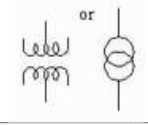 |
4 | Three winding transformer | 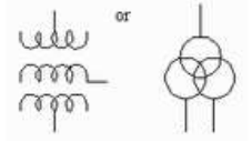 |
5 | Current Transformer (CT) | 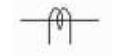 |
6 | Voltage transformer or Potential transformer (PT) | 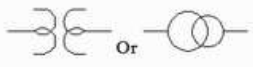 |
7 | Circuit Breaker (CB) | 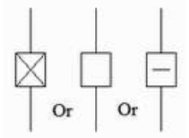 |
8 | Circuit breaker with isolator | 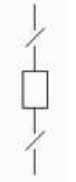 |
9 | Isolator or Group Operating Switch(GOS) |  |
10 | Lighting Arrestor (LA) | 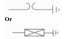 |
11 | Earth Switch (ES) | 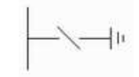 |
12 | Wave or Line trap |  |
Cable Selection
The power cord, the nerves of any electrical network. The cables make up the majority of the investments in the electrification project. But they are also the most susceptible to failure. The majority of cable faults can be caused by an incorrect selection. In this article, it is aimed at solving the problem of how to choose the right power cable.
The selection of the parameters
I. a) Rated voltage: the rated voltage of the system in which the cable is to be installed and used. Also, it is important to know how to use the system. The rated voltage of a cable is usually defined as a double value (for example, to 6.6 kv (EU) / 11 kv (E)).
"CE" means that the cable can be used for a given voltage in a non-grounding-type and effective with no connection to the system. "E" means that the cable can be used at a particular voltage to a properly grounded system. So, for cables with a rated voltage of 6.6 kv (EU) / 11 kv (E), it can be used to 6.6 kv to ground-based systems, and the inefficiencies of the 6.6 kv to ground-based system, or a permanent an 11 kv to ground-based systems. And I will.
II. Conductor type: used cables and wires are made of copper or aluminium. As you may know, the excitement, and the isolation of the cross-sectional area, and the method of installation, the rated DC current flow, intermittent flow, and a is the unit price of copper cable is much higher than that of aluminium. It is. the cable with the cable.
III. Type of protection: Most of the cables today and be insulated with PVC, XLPE, or. Of course, for the same conductor material nominal voltage, the isolation of the cross-sectional area, and the method of installation, the rated DC current flow, intermittent flow, and a is the charge per unit length of the cross-linked polyethylene insulation of the cable can be significantly higher. It is. Insulated, PVC wire.
IV. Cable types: Armored or an unarmored cables are used in home appliances and plant equipment, such as roof drainage system, and the pre-built reinforced concrete channels, cable trenches. The armoured cable is required, for the installation of underground cable.
The armour can be of galvanized steel or aluminium, wire, or strip. Typically, this armor is connected to the factory floor, with a preference for only one of ends of the cable, as is usually the receiving end of it.
V. dc Reviews-DC reviews-cables (aluminium / copper conductors are available in the catalog of the various cable manufacturers. Please keep in mind, however, that this list provides a constant current for standard installation terms and conditions. In fact, you can't get it, or save these general terms and conditions. Therefore, given the low price, the coefficients can be used to achieve real-DC-rated.
VI. The evaluation factors, the most important evaluation factors to consider are:
(a) The par value of the land and the sky, the temperature variation of
(b) the Coefficient estimate of the temperature fluctuations
(c) the ratio of the estimate of the vibration and the thermal resistance of the soil
(d) the Group-rating factor of vertical space
(e) a Group-rating factor of vertical space
All of the evaluation factors for the different conditions are also provided in the cable from the manufacturer's catalog.
VII. The Voltage drop in the cable is composed of a resistive and a reactive resistance. Therefore, the current through the resistor causes a voltage drop. This reduction has no effect on the load bar.
The actual voltage drop in the cable, is shown in mph in the cable from the manufacturer's catalog for a variety of kinds of connections. It is also found in the Indian standard, 1255 (implementation of the standard for the installation and maintenance of power cables up to 33 kW).
It is necessary to calculate not only the steady-state voltage drop, but also the acceleration of the voltage drop at the beginning of a lot of work.
You will also need to confirm that the steady-state voltage at the load terminal is 10% or less, and the acceleration voltage at the load terminal is 15% or less.
Click to Select the Check:
If its clear principle has not yet been defined during the planning stages of the network, or in accordance with the specifications.
MV enable one-cables
As a band, it is suitable for the majority of the delivery of the tasks. On systems with a large number of circuits, the cables may be divided into a number of sections, each with its own source of power. In this way, each section may be sent to the reserve capital of a neighbouring department.
If there is a wrong to the circuit breaker being turned on by accident, this does not impact on the safety and security of its devices, such as vending machines, or you can stop by for all to load and short-circuit currents of the load, even if there is a ground fault in one of the other short-circuit conditions.
MV-switches-double-busbar
For technical or contractual reasons, some of the requirements can only be met in the use of double bands, such as:
1. If there are two (or more) of the feeder lines should be dealt with separately (for example, the feed lines and a variety of tools, or the rigorous separation of the in-plant generation and the public grid);
2. If the loads can have an impact on the quality of the food, caused by the voltage fluctuation and flicker), and any other devices that are prone to interference.
3. As the costs of the various weights have been divided into the "safe" and "less safe" bonds (i.e. bonds with a variety of accessibility requirements);
4. If the network needs to be divided into two subnets, due to the limited short-circuit rating of the equipment that has been added. Switch on, you can use the balance sheet to the variable load, the current consumption.
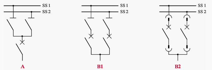
Fig Double Bus Bar arrangement
Variety of switches are combinations that have been investigated and compared with each other, in the proper performance of the criteria.
A lightning rod or lightning rod is a metal rod mounted on a structure that is designed to protect the structure from lightning strikes. When the lightning strikes the tree, it is best to stop along the whole length, and can be implemented on the ground through a wire, instead of passing through the structure, where it could result in a fire or an electric shock hazard. Lightning rods are also called tips, air terminals, or strike the end of the device.
In a lightning protection system, a lightning rod is a single component in the system. A lightning rod requires a ground connection with the performance of their protective function. Lightning rods come in a variety of shapes, including flat, hard, sharp-edged, round, flat tires, or even bushy bristles. The most important attribute common to all lightning rods is that they are all made of conductive materials, such as copper. Copper and its alloys are the most common materials used in lightning protection systems.
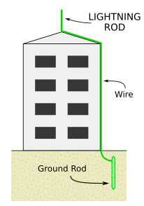
The idea is to create one or more, preferably, lightning strikes, points to a low-impedance conductive element. Then, carry out, and distribute a lightning currents to the ground. This is a coherent system allows you to capture the distribution of the castle, while the protection of the structure. There are five types of lightning protection systems for the protection of the structures of releases:
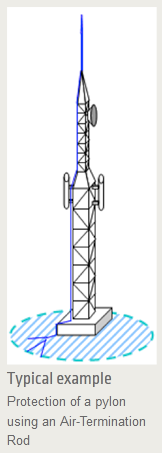
1. The Air Terminal, Lightning Protection
Benjamin Franklin invented the lightning rod in the year 1753. This is lightning-fast guide is divided into the 2-to 8-foot-tall conical shaped metal bar that dominates the protected structure, and is connected to at least two of the conductors, and the two grounding systems.
As for the protection of the radius of this type of air terminal is to be limited to approximately 30 m (lightning protection system-level = IV, height = 60 m), which is typically only used to protect small buildings, structures, or areas, such as poles, chimneys, tanks, turrets, towers, antennas, etc., etc....
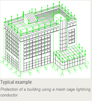
2. Pure Thread of Lightning Protection Systems
This lightning protection system is derived from a cage, consists of a mesh of conductors, which cover the walls and ceiling of the protected structure.
The Air terminals are located on the edge of the roof, and on the high points. A network of pipes running along the outer perimeter of the roof. This network will be complemented by the cross-sectional elements. The size of the grid can vary from 5 to 20 meters, depending on the required capacity.
The top-bottom wires are attached to the wall in combination with the roof, the grid, and the primary is connected to a special grounding systems. The distance between the two bottom tracks of 10 to 20 meters, depending on the level of lightning protection system.
Most of the lightning current is discharged through the wire and the ground systems, the one closest to the lightning website.
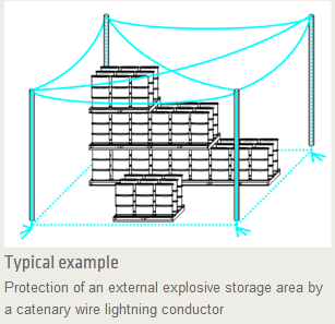
3. Lightning-rod chain and wire -
This lightning protection system, which uses a similar principle to the wire mesh of the cage, consisting of an array of strings, but at some distance away from the protected structure. The goal is to avoid the lightning currents, come into direct contact with the structure.
The conductors of the circuit are wires on top of the protected structure, as they are associated with the nerves, and ground, and a special ground-based systems. The size of the grid and the distance between the lower conductors are subject to the same rules apply as for the lightning protection system is a network of wires.
The protection requires some mechanical studies, the strength of the materials used in the gsm network, the pressure, the resistance of the wind and weather conditions, etc., etc.) as well as the determination of the insulation away.
Lightning rod, a chain of threads to be used for the protection of open space, where there is no structural support, hazardous storage is concerned.
4. Protect it with "natural" ingredients
Items that have a lightning protection system to function, but that were not being used.
Note: all the conductive parts of the structure or premises to be able to take part in external protection, due to their ability to absorb lightning and power-line conduct lightning current. They can be used to replace all or part of the inheritance of windows explorer or in addition to an external installation.
These can include:
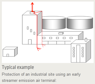
It's the principle of the early streamer emission lightning conductor for the product is artificially created, with the help of an ionization device, the pre-existing trend towards the leader, and that of other "natural" for the rising's leaders, in order to establish a prime lightning strike point. lightning absorption rate is quicker than the use of a lightning rod, and it can be used for the protection of the areas are spread out over a wider range, allowing it to provide protection for large structures.
The protection of your player depends on the amount of the advance, and the lightning rod (r, µs), the extent and the effectiveness of the protection, the maximum value is 120 feet (Level III), height = 60 m) away.
To be an effective and reliable electrical grounding is required, a good test, and analysis of the project, its location, and nature of the buildings and installations of electrical, electronic, and used in the system. The approximate calculation of the grounding electrode system must be based on reliable data on the participation of the basis of resistance and short-circuit currents of the system, as well as their length.
The calculation of the design of Protective / earthing electrode
The design calculations shall be approved by the engineer, and shall be based on methods that have been described in the above-mentioned standards. Calculations of the following parameters:
The basis of the resistance of the entire system and its components
The improvement of the Earth's potential
And, the sensor and the net opportunities within and outside of the gate (refer to ground, and connect the gate)
Of the requirements for the high resistance of the surface layers
Thread Specification
With the increase of the earth's potential may be higher than the EUROPEAN borders, which correspond to the os, format, unless there are special precautions to be taken in order to take into account the sent options.
The step motor, touch screen, and the potential of grids need to be within the limits that have been determined in accordance with the standards of the IEEE, 80, BS, 74303 to the surface. The formula for the maximum permissible body current for up to 50 kg of body weight.
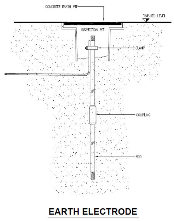
Ground Connections
Grounding electrodes shall be equipped with a system of wires, forming a grid, to be buried in the vicinity of the surface of the soil, eliminate errors, and, if necessary, by one or more of the following electrodes:
1. As a system, connected to steel rods, driven into the ground
2. Steel structures, steel structures, which are in direct contact with the ground.
3. Steel is to be buried in concrete.
Clean the floor, or the electrode is placed on the ground
In net, the system needs to be designed in accordance with the above sub-heading "General calculations above, in order to reduce the envelope, the walls, and the net potential, taking into account the combination of the net, guide, the length of the burial of the other tour guides, and bars, but without any rails outside of the fence. Due attention must be paid to the non-linear distribution of the fault current, which leads to the appearance of the greatest talents in the corner of the screen.
The net asset value of the threads shall be in accordance with the short-circuit currents, taking into account the parallel paths, with a minimum conductor size of up to 300 mm 2 for copper.
In the evaluation of the calculation of the ground grid and the existing distribution of ratios = 0.8, the specified short-circuit current is assumed.
As well as the location of the ground grid is used for the exterior of the building, and the soil depth of 2 m below the ground surface, or at least 1 m below the standard, depth and power cables.
Interconnected Ground Rods
As a means of approximate calculations show that a grid was not in a position to reduce the potential for the required values, that is, the grid needs to be expanded with each other and connected to ground rods, driven into the ground or drilled wells.
The rods need to be installed on the inside of the enclosure to the area as possible, in accordance with the grounding of the fence to the other side. The distance between the bars should not be less than the length of it, and unless otherwise specified, for mathematical reasons as well.) The rods need to be connected to each other in groups of 4 to 0 bars and rods, of the yellow-and-green-isolated PVC stranded copper wires to form a ring. Each group will need to be combined with any grid, double-insulated copper-lost research of the elements.
Individual bars can be connected directly to the network on the condition that the control rods can be detached for a bar crawl.
The rods are installed in the well drilling, and can be used to achieve a lower specific to soil layers to a depth that is not accessible to the public bar, or if there is a genre of one, and you can't drive from the bars on the move. After the installation of the rod and the hole needs to be filled with a low density, resistance to liquid mixtures, which may not shrink after melding, to ensure a good contact between the rod and the ground, over the entire life cycle of the plant.
Reinforcing Steel of the Building as Earth / Ground Electrode
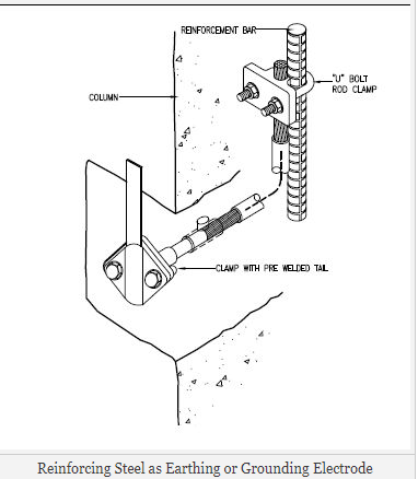
The steel reinforcement in the foundation of a building is the most important electrical components that can be used as auxiliary electrode, and subject to approval by the Engineer. The contractor will need to show the calculations that the short-circuit currents and DC stray currents will not be able to defects in the structure.
Steel reinforcement mesh in the upper floors of a building, it can also be used for the purpose of guarding the walls and the sensor of the building, subject to the approval by a structural engineer.
Tour Guides Outside of The Perimeter of The Fence
As for the design, calculations show that the motor and sensor capabilities are outside the scope of a hedge, fence or wall to be higher than the exposure limits, additional threads will need to be provided in the ground, behind a fence, in the form of rings around the entire area.
The distance between the wires of the fence and the depth must be specified in the project, so the first step to the sensor, the possibilities are within the permissible limits.
The minimum size of the bar, 70 mm2, and it needs to be connected to the case, or set of conductors, 70 mm2, in any corner of the site, at a distance of no more than 100 meters. This thread should not be included in the calculations are given above.
Earthing, grounding of the gas-insulated switches (CIS -))
The ground of a gas insulated switches (CIS), the system must take into account the specific concerns of the walls, and the sensor of the entity in accordance with the specified standards. However, the floor guide, with yellow-and-green-isolated PVC stranded copper with a minimum aggregate principal conductor size of up to 300 mm2.
How to determine the power factor
The power factor is the ratio between the "present day" of the power, and the "apparent" is about the electrical power of the system.
The real power = power = kw.
Apparent Power = voltage x Amps = kVA
Reactive power = magnetizing power = fields.
VAR:
Active power, also known as real power (measured in Watts or kW), and performs Useful Work. Electrical appliances, such as electric motors, transformers, the required reactive power, and the creation of a magnetic field, and to allow the work to be carried out. This reactive power is known as reactive, v, current, power, reactive power, the VARA measured from the vars menu or gallon. Total power output-it is referred to as volt-amps and is measured in VA or kVA
Reactive power required by a lot of taxes to the magnetization currents of motors, transformers, welding machines, electric arc furnaces, valves, lamps, and ballasts
The calculation of the power factor correction:
Power factor correction enables you to calculate your imaginal power, real power, reactive power and phase angle. Consider the equation of a right-angled triangle. Thus, for the calculation of the angle of inclination, you will need to know what is the right of the cosine, sine, and tangent. You will also need to know the Pythagorean theorem (c2 = a2 + b2), for the purpose of calculating the sides of a triangle. You will also need to know what unit it is, is a kind of energy. Apparent power is measured in Volt-amperes. Real power is measured in Watts, and Reactive Power and is measured in units called V-Amps-Reactive (VAR). There are a variety of formulas for the calculation of one of them, and all of them will be discussed in this article.
Actions:
1. The calculation of the impedance. (Assume that the resistance of the load, the apparent power in the picture above). Therefore, in order to find the resistance, we can use the Pythagorean theorem: c = √ (a2 + b2),
2. Therefore, the total resistance will be shown as "C" is equal to the square of the Real power-in addition to the square root of the Reactive Power, and then take the square root of the answer. Z = √ (R2 + X2)
3. Find the phase angle. So, now that you've got hypotenuse, what is your immune system. You can also give your soul a side that is the true power, and there is the other side of that is, it is in your reactivity ability. So, for the price, you may make use of the services of any of the rules, it was concluded earlier. For example, we use the hyperbolic tangent of law, that is, on the other hand, it is separated by a similar hand, a reactive/false).)
tan θ =
4. Find the phase angle. So, now that you've got hypotenuse, what is your immune system. You will also have to have an open side, this is your true strength, you need to have a second side that is in your reactivity ability. So, for the price, you may make use of the services of any of the rules, it was concluded earlier. For example, we use the tangent line at the right of that, on the other hand, are divided by an similar to part (a Reactive approach Where)
θ = tan-1 
5. The calculation of the Total Current (Amps). Your current in units of amps has also been considered as "One". The formula used to calculate the current, voltage, divided by the resistance.
Current(A)=
6.The calculation of the imaginary power, which is represented as 'S'. For the calculation of the apparent long, you don't need to use Pythagoras ' theorem, for yours is the hypotenuse I was in your immune system. Keeping in mind that it is the apparent power in the units of the unit, we are able to calculate the apparent power by the following formula: Voltage squared divided by resistance
Apparent power (S) = 
7. How to calculate the real power, which is represented as "P". For the purposes of calculating the true power, you must use the power that you created in step four. The real power is in units of W, and is calculated by multiplying the current in the square due to the resistance in the circuit is
Power = current2 * Resistance
8. Calculate the power factor
For the purposes of calculating the power factor, you need to use the following information: Watts and volt-amps. You need to have the calculation of the information provided in the previous steps. The formula for the power factor, which may be represented as, Pf, what was shared by V-power amplifiers
Power factor = 
1. Series Compensation:
Series compensation is basically a powerful tool to improve the performance of EHV lines. It consists of capacitors connected in series with the line at suitable locations.
Advantages of series compensation:
1.Increase in transmission capacity
The power transfer capacity of a line is given by
P =  sin
sin
where, E is sending end voltage V is receiving end voltage X is reactance of line δ is phase angle between E and V
Power transfer without and with compensation:
P1 =  sin
sin
P2 =  sin
sin
 =
=  =
= 
where K is degree of compensation.
2. Improvement of System Stability
For same amount of power transfer and same value of E and V, the δ in the case of series compensated line is less than that of uncompensated line.
P =  sin1
sin1
P =  sin2
sin2
 =
= 
A lower δ means better system stability. Series compensation offers most economic solution for system stability as compared to other methods (reducing generator, Transformer reactance, bundled conductors, increase no. of parallel circuits.
3. Load Division between Parallel Circuits • When a system is to be strengthen by the addition of a new line or when one of the existing circuit is to be adjusted for parallel operation in order to achieve maximum power transfer or minimize losses, series compensation can be used. • It is observed in Sweden that the cost of the series compensation in the 420 kV system was entirely recovered due to decrease in losses in the 220 kV system operating in parallel with the 420 kV system.
4. Less installation Time • The installation time of the series capacitor is smaller (2 years approx.) as compared to installation time of the parallel circuit line (5 years approx.) • This reduces the risk factor. • Hence used to hit the current thermal limit. • The life of x-mission line and capacitor is generally 20-25 years.
Disadvantages
1. Increase in fault current
2. Mal operation of distance relay- if the degree of compensation and location is not proper.
3. High recovery voltage of lines- across the circuit breaker contacts and is harmful.
Shunt Compensation:
For high voltage transmission line the line capacitance is high and plays a significant role in voltage conditions of the receiving end. • When the line is loaded then the reactive power demand of the load is partially met by the reactive power generated by the line capacitance and the remaining reactive power demand is met by the reactive power flow through the line from sending end to the receiving end.
When load is high (more than SIL) then a large reactive power flows from sending end to the receiving end resulting in large voltage drop in the line. • To improve the voltage at the receiving end shunt capacitors may be connected at the receiving end to generate and feed the reactive power to the load so that reactive power flow through the line and consequently the voltage drop in the line is reduced.
To control the receiving end voltage a bank of capacitors (large number of capacitors connected in parallel) is installed at the receiving end and suitable number of capacitors are switched in during high load condition depending upon the load demand. • Thus, the capacitors provide leading VAr to partially meet reactive power demand of the load to control the voltage.
If XC =  be the reactance of the shunt capacitor then the reactive power generated of leading VAr supplied by the capacitor:
Qc = 
Where V2 is magnitude of receiving end voltage
When load is small (less than SIL) then the load reactive power demand may even be lesser than the reactive power generated by the line capacitor. Under these conditions the reactive power flow through the line becomes negative, i.e., the reactive power flows from receiving end to sending end, and the receiving end voltage is higher than sending end voltage (Ferranti effect). To control the voltage at the receiving end it is necessary to absorb or sink reactive power. This is achieved by connecting shunt reactors at the receiving end.
If XL = ωL be the reactance of the shunt reactor (inductor) then the reactive VAr absorbed by the shunt rector:
QL = 
Where V2 is magnitude of receiving end voltage
To control the receiving end voltage generally one shunt rector is installed and switched in during the light load condition. To meet the variable reactive power demands requisite number of shunt capacitors are switched in, in addition to the shunt reactor, which results in adjustable reactive power absorption by the combination.
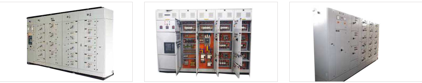
PCC panels are an integral part of the electrical system, the industry, the true strength of the sector is regulated. Perfect Products (India) is well-known for its high-quality, PCC panels, engineered, and manufactured to the specifications of the customer. High-quality connectors and cables are vital in order to ensure the safe and efficient operation.
1. We have been producing PCC panels, each with a nominal power ranging from 630A to 6300A
2. PCC panels are manufactured in a great spread in texture.
3. High-quality electrical insulators may be used to ensure safety.
4. At the request of the customer, a double radiator, a thermostat, and a back treatment can be provided.
5. Convenient to use, safe and reliable
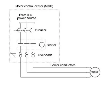
MCC stands for a motor control center, and more. It consists of a tray, motors, and fans. Enemies have been designed on the basis of the rated current of the motor. In the majority of MCCS will have automatic/manual software. Under manual control, the motors can be operated manually. In the automatic mode, an external signal is required in order for the engine to start it. The signal from the remote control. The operation of the engine, the indicators that will be also included in the "control panel".
A motor control center (MCC), a node consists of one or more closed areas with a common power bus, and it consists primarily of the engine control unit. Motor control centers are in modern practice, the factory assembly of several motor starters. The motor control center you can include variable frequency drives, programmable controllers, and metering equipment, and it can also be an electrical service entrance for the building.
1.GENERAL
This segment covers the thorough necessities of low voltage switchboard, shall be as below
a). Supply voltage: 415V± 10%, 3Ph
b). Frequency: 50 Hz ± 5%
c). Combined voltage/frequency variation: ±10%
d). System earthing: Solidly Earthed (TNS)
2. SWITCHBOARDS
This specification covers the design, fabrication, and testing of industrial steel structures, and the LV-panel assemblies that are used in electrical equipment up to 1000 VOLTS. Usually, LV panels, the contents of this specification are referred to as LV-block panels. In this specification, reference is made to the later-described, or if you specified". For more information about the requirements, please see the one-line diagram.
3. CODES AND STANDARDS
The LV switchgear shall be designed, manufactured and tested in accordance with the latest relevant sections of the IEC code. It is always for the latest version. LV switch gear switches are manufactured in India shall be designed, manufactured and tested in accordance with IEC-IS accounting standards, rules and regulations. In general, the sequence is as follows:
The Single line diagram As a reference to the Single-line Diagram that was created in the second part of this specification, shall be deemed to be references to the corresponding images)
Approved Drawings & Datasheets
Specification
BOQ
IS/ International Standards
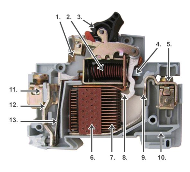
MCB:
A miniature circuit breaker is an electromechanical device designed to protect electrical circuits from overcurrent. A term used to describe an electrical failure caused by an overload or short circuit.
At that time, we used fuse wires to protect against overcurrent (in fact, we were selling it!). The principle was pretty simple. Overcurrent literally heats and melts the fuse wire rapidly, "blowing" the fuse wire by breaking the electrical connection, thus protecting the rest of the electrical circuit.
This is enhanced because MCBs are usually not destroyed during overcurrent and can be reused. They are also much easier to use, provide "on / off"
convenience for circuit insulation, and the conductors are housed in a plastic casing, making them much safer to use and operate.
It is important to note that MCBs do not protect humans from electric shocks caused by "leakage". This service is provided by RCD and RCBO.
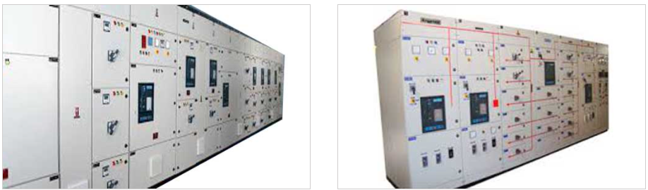
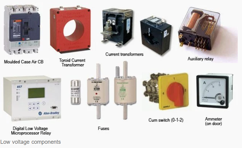
LT Panel Components
Low voltage switchgear assemblies
The core components are:
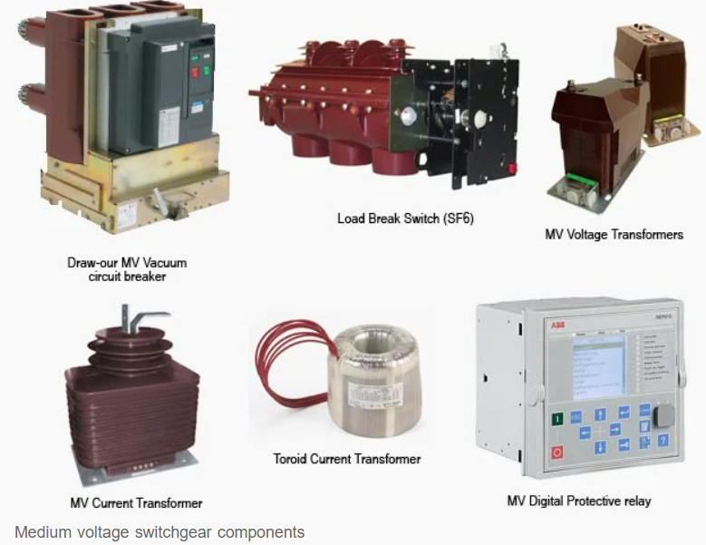
Medium Voltage Switchgear
The key components are:
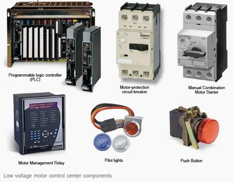
Low voltage motor control centers
The components for LV motor control centre are:
Medium voltage starters
The key components for MV starters are:
References:


