Unit - 5
Industrial Electrical System II
Diesel Power Plant / DG Set: A power plant that uses a diesel engine as a prime mover to generate electrical energy is known as a diesel power plant / DG set. Diesel engines are used as prime movers in diesel power plants. Diesel burns in the engine, and the product of this combustion acts as a "hydraulic" to produce mechanical energy. Diesel engines drive alternators that convert mechanical energy into electrical energy. Due to the high price of diesel, the cost of generating electricity is quite high, so such power plants are only used to generate a small amount of electricity. Thermal and hydroelectric power plants are always used to generate large volumes at low cost, but diesel power plants have low electricity demand, lack of sufficient coal and water, and lack of transportation facilities. It is preferred in places where you are. Not enough. These plants are also used as standby sets to continue to supply critical points such as hospitals, radio stations, cinemas and telephone exchanges.
Advantage:
The design and layout of the plant is very simple.
Cons: Disadvantages:
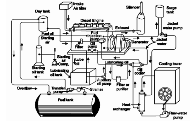
Fig 1 Schematic arrangement of Diesel Generator Set
d. Cooling system. The heat released by the combustion of fuel in the engine cylinder is partially converted to work. The rest of the heat can pass through cylinder walls, pistons, rings, etc. and damage the system. Cooling is provided to keep the temperature of engine components within safe operating limits. The cooling system consists of a water source, a pump and a cooling tower. The pump circulates water through the cylinder and head jacket. Water draws heat from the engine and becomes hot in itself. Hot water is cooled in a cooling tower and recirculated to cool.
e. Lubrication system. This system minimizes wear on the friction surface of the engine. It consists of a lubricating oil tank, a pump, a filter, and an oil cooler. Lubricating oil is pumped out of the lubricating oil tank and passed through a filter to remove impurities. Clean lubricating oil is sent where lubrication is needed. The oil cooler built into the system keeps the oil temperature low.
f. Engine starting system. This is the arrangement that first spins the engine during start up until firing begins and the unit operates at its own power. Small sets are manually started by the handle, but for larger units, compressed air is used for starting. In the latter case, high pressure air flows into several cylinders, which act as reciprocating air motors to rotate the engine shaft. The fuel is put into the remaining cylinders and the engine starts on its own.
g. Alternator. The alternator is a salient synchronous generator that is self-excited and self-regulated by the excitation unit. The excitation unit consists of a choke, CT, a diode, and a capacitor. The voltage can be adjusted within 2.5% of the nominal voltage from load up to full load with o-rated pf. The choke is for adjusting the terminal voltage when there is no load. CT is for adjusting the terminal voltage under load.
Key takeaways:
Uninterruptible Power Supply (UPS) UPS is an uninterruptible power supply. It is a device that continuously supplies power even if the main power supply (utility) fails. The UPS is installed between the main power supply and the equipment to be protected. UPS is used to protect different types of equipment. One of the common uses is for computers, especially in important equipment in data centers and large organizations.
UPS Operation:
UPS operates by converting the alternating current (a.c.) power supply of the main power supply to a direct current (d.c.) voltage. The part of the UPS that does this is called the rectifier. Then use the output from the rectifier to charge the battery. Batteries can be powered in the event of a mains failure. The voltage from the DC rectifier (or the battery in the event of a mains failure) is converted to AC. The UPS inverter powers the equipment.
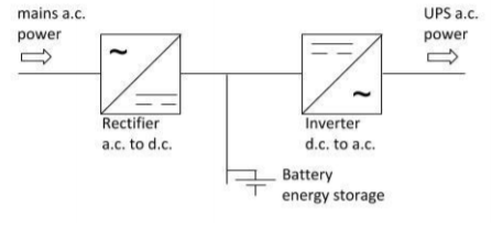
Fig 2 Operating Principle of a UPS
Figure 5.2 UPS Principles In UPS, energy is typically stored in a flywheel, battery, or supercapacitor. Compared to other immediate power systems, UPSs have the advantage of immediate protection against input power interruptions. Battery life is very short. However, this time is sufficient to safely shut down connected devices (computers, telecommunications equipment, etc.) and turn on standby power. The UPS can be used as a protective device for some hardware that can cause serious damage or loss in the event of a sudden power outage. Uninterruptible power supply, battery backup, and flywheel backup are other names commonly used in UPS. Available sizes of UPS units range from 200 VA used for solo computers to several large units up to 46 MVA.
UPS Type:
1. Offline:
UPS This UPS, also known as a standby UPS system, can provide only the most basic functionality. Here, the main source is the filtered AC main (shown in the solid path in Figure 5.3).
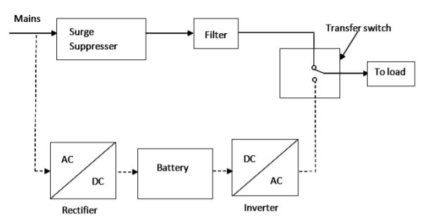
Fig 3 Off-Line or Standby UPS
In the event of a power failure, the transfer switch selects the backup source (indicated by the dashed path in Figure 1). Therefore, it is clear that the standby system will only start working if the main fails. In this system, the AC voltage is first rectified and stored in a battery connected to the rectifier. In the event of a power outage, this DC voltage is converted to an AC voltage by the power inverter and transferred to the load connected to it. This is the cheapest UPS system and provides surge protection in addition to backup. The transfer time is about 25 ms and may be related to the time it takes the UPS system to detect the lost commercial voltage. The block diagram is shown below. Figure 5.3 Offline or standby UPS.
2. Online UPS:
This type of UPS uses a dual conversion method. Here, the AC input is first converted to DC by a rectifying process to store it in a rechargeable battery. This DC is converted to AC by the inversion process and given to the connected load or equipment (Figure 5.4). This type of UPS is used when electrical insulation is required. This system is a bit costly due to the design of the always-on converter and cooling system. Here, a rectifier, which is powered by normal AC current, drives the inverter directly. Therefore, it is also known as a double conversion UPS. The block diagram is shown below. Figure 5.4 In the event of an online UPS power outage, the rectifier does not affect the circuit and the transfer switch supplies the stable power stored in the battery connected to the inverter to the load. When power is restored, the rectifier will start charging the battery. The charging current is limited to prevent the high power rectifier from overheating the battery. This UPS system operates with zero transfer time while the mains are out of order. The reason is that the backup source acts as the primary source instead of the main AC input. But with the presence of inrush Current. In this system, large load step currents can result in transfer times of approximately 4-6 ms.
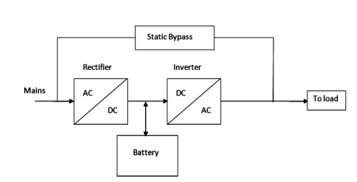
Fig 4 On-line UPS
3. Line Interactive UPS:
Line Interactive UPS is used for small business and department servers and the web. This is similar to an offline UPS. The difference is the addition of a tap replacement transformer. Voltage adjustment is done by this tap change transformer by changing the tap according to the input voltage. This UPS provides additional filtering to reduce transient losses. The block diagram is shown below. Figure 5.5 Line Interactive UPS
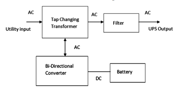
Fig 5 Line interactive UPS
Battery Types: UPS systems typically use the following battery types:
Battery Sizing: The manufacturer provides battery sizing information. Normally, this information assumes room temperature is 25oC. Batteries that operate continuously at different temperatures need special calculations for that temperature. Batteries are typically sized using:
Wattage per cell or amperage per cell. Wattage Method Per Cell The information provided about lead-acid batteries, typically designed for short discharge times (5-120 minutes), is in the form of kilowatts per cell tabulated for various backup times. The required [Watts] for each cell is given by the following formula.
𝐴mperes = {(𝑉𝐴 × 𝑝𝑓) / × 𝑁} + 𝐴1 Where VA = load VA,
pf = power factor
η = UPS efficiency
N = number of cells
Al = additional load connected to the battery (in VA)
Long-term discharge lead-acid batteries with amperes per cell and most nickel-cadmium batteries are sized using a chart of amperes available for a specified period of time. The amperage required for each cell is:
𝐴mperes = {(𝑉𝐴 × 𝑝𝑓) / × 𝑉𝑑𝑐} + 𝐴1
Where VA = load VA
pf = power factor
η = UPS inverter efficiency (DC to AC)
Vdc = average discharge voltage
Al = additional load connected to the battery (A)
Key takeaways:
Elevators can be defined as electric lifts used to vertically transport goods and people between floors of a building using silos. As always, they are powered by electric motors that drive counterweight system cables for drive transactions such as hoists. Otherwise, pump hydraulic fluid to raise a cylindrical piston such as a jack. These are used in many fields such as agriculture and manufacturing. Elevators are categorized into different types based on our requirements. Elevators are often used in modern high-rise buildings, especially when wheelchair ramps are not practical.
Elevator Parts and their Functions:
Speed Governor
Elevator speed control systems are known as governors. If the elevator travels above the speed limit, the governor controls the speed. It is usually attached to the bottom of the car and is also known as the governor rope. Electric motor
When the lift faces a serious condition, the electric motor prevents it and provides the smooth function of the lift.
Elevator Rail
If the elevator rails are functioning properly, you can slide up and down in the elevator.
Cabin
This is the main part of an elevator designed for the shipment of goods and services or the passage of people.
Elevator shaft lift cabin moves in this space. You can change the position of the shaft depending on the type of elevator.
Door
Like regular doors, elevator doors are for entry and exit. There are two types of elevator doors: manual doors and automatic doors.
Manual Door:
These types of doors are opened with the help of those who want to ride the lift.
Automatic Door:
An automatic door is a type of door that opens automatically when the door operator supplies power.
Drive Unit
Everything that works under electricity needs to be equipped with a motor to work. The drive unit is the part that contains the motor that drives the lift. buffer
A shock absorber is a device at the bottom of an elevator designed to protect people. The buffer can stop a descending vehicle by accumulating or dissipating the kinetic energy of the vehicle.
Safety device This is a mechanical device attached to the elevator for safety reasons. If the lift moves downwards at maximum speed or above the speed limit, the safety device can maintain safety and safe movement. Well, these were part of the elevator and its features. Traveling by elevator is great. However, the skills and knowledge of technicians and the effective maintenance of elevators can make a trip extraordinary.
Operating Principle
The operating principle of an elevator or lift is similar to a pulley system. The pulley system is used to draw water from the well. This pulley system can be designed with a bucket, a rope with wheels. The bucket is connected to a rope that runs through the entire wheel. This makes it easy to draw water from the well. Similarly, current elevators use the same concept. However, the main differences between the two are: The pulley system is manually operated, but the elevator uses advanced mechanisms to handle the load on the elevator. Basically, an elevator is a metal box of various shapes connected to a very sturdy metal rope. A sturdy metal rope passes through the pulleys of the elevator in the engine room. Here the sheave is like the wheel of a pulley system for squeezing a metal rope. This system can be operated by a motor. When the switch is turned on, the motor can be operated when the elevator moves up or down or stops. Elevators can consist primarily of various elevator components or elevator components, including speed control systems, electric motors, rails, cabins, shafts, doors (manual and automatic), drive units, buffers, and safety devices.
Elevator type:
There are different types of power units or elevator machines used to drive electric elevators. Elevator machines can be divided into two general classes in terms of how power is transmitted to the ropes of a car.
1. Drum
2. Traction.
Elevator machines basically consist of a motor, a drum or traction pulley, a brake, and a motor drum drive. The drive may consist of a direct shaft connection between the motor and the drum, or it may be a trough gear system.
Drum Elevator Machine
It consists of a spool-shaped drum that is fitted with the ends of the rope and allows the rope to be wound and unwound during the operation of the car. There are generally two types of drums used. Drum here means a hoisting drum. Another drum used is simply a traction drum, a type of pulley sheave. Structurally, both types of drums have grooves, which are spiral for drum elevators and straight for traction elevators.
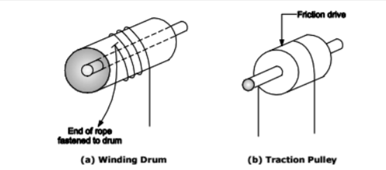
Fig 6 Drum, Traction elevators
In the operation of the drum elevator machine, when you put the power on the diving gear and turn it in one direction, the rope is wrapped around the drum and the car rises, and when the power is reversed, the drum rotates in the opposite direction and payment is made. Remove the rope and lower the car.
The weight of the car is balanced by the counterweight, which reduces the energy spent driving the car. Automatic devices are used to properly and safely control the movement of vehicles.
In terms of location, there are two types of machines:
The rope is not wrapped around the drum, but a continuous rope from the car to the counterweight passes through the eight drive pulleys.
The traction machine winds up the hoist rope and carries it from the top of the sheave to the counterweight, depending on the grip of the rope on the sheave to provide sufficient traction to lift the load.
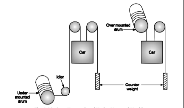
Fig 7 Overmounted and under mounted machines
Elevator Motor
To ensure rapid acceleration and deceleration, the inertia of moving parts should be kept as low as possible. Therefore, it is preferable that the motor for elevator service is designed by using the armature of a low-speed motor having a relatively small diameter.
In general, the motor speed should not exceed 900 rpm.
Power Calculation:
There are three factors to consider when determining the size of the motor required for a particular installation:
You need to consider that load when calculating the lifting load.
Part of the weight and load of the car is counterbalanced by the counterweight. Therefore, only unbalanced loads need to be taken into account.
Efficiency is the overall efficiency that takes into account various friction and electrical losses. H.P. You can find what you need using the following formula:
H.P = (L * S) / (E * 33000)
Starting torque requirement:
Elevators require more starting torque than is required to keep the same elevator running at rated speed and load. This is mainly due to static friction. Therefore, a motor suitable for elevator work must be able to generate 2 1/2 to 3 times the starting torque represented by that motor.
Horsepower rating (that is, full load torque).
Motor builders do not design all motors with the same ratio of starting torque and full load torque. In some cases, inrush current imposes limits that reduce the amount of starting torque that could otherwise be obtained.
D.C. Motor:
The type of D.C. motor that is best suited for elevator service depends to a large extent on the type of service, that is, the speed and frequency of the slope.
Elevator motors are one of the main tasks of not only loading and unloading, but also rapidly accelerating and decelerating the car. This should be achieved smoothly without jerk, which can be offensive to passengers. The starting torque must be at least 225% of the rated full toad torque. Motors with speed fluctuations of more than 15% from no load to full load are not recommended for elevator service.
The self-starting repulsion induction type single-phase motor can also be used for elevator service.
Composite winding motors are recommended for freight transportation. Series windings provide high starting torque, an integral part of heavy load work. For passenger service, either compound winding motors or shunt winding motors give satisfactory results. Most DC motors, whether shunted or composite windings, have the appropriate rectifying pole windings to ensure sparky rectification in both directions of rotation.
A.C. Motor:
Two common types of A.C. motors suitable for elevator service are:
(1) Squirrel-cage motor
(2) Slip ring motor.
Squirrel-cage motors are widely used up to about 20hp due to their simplicity and the need for a relatively simple type of controller.
The power consumption of the squirrel-cage motor is slightly higher than the power consumption of the shipping machine, but it is slightly more reliable due to the lack of slip rings and fewer controller parts.
Slip ring motors with the same rating are more expensive and have a slightly lower power factor than squirrel-cage motors. A low-speed type A.C. motor is available, and the vehicle speed is increased.
As high as 400 feet per minute. All A.C. Elevator Motor Services Like 0.C Must Be El Specialized.
The work of evator
Elevator Control System
Elevator control systems can be broadly divided into two groups.
In the Leo static control method, a rheostat is included in the field and armature of the motor, and speed control is possible by changing it.
In variable voltage control, the input voltage applied to the motor is changed in some way to control the speed.
Key takeaways:
1. Elevators can be defined as electric lifts used to vertically transport goods.
2. The operating principle of an elevator or lift is similar to a pulley system.
3. The pulley system is manually operated, but the elevator uses advanced mechanisms to handle the load on the elevator.
Batteries and other energy storage devices store energy so that it can be used when required. In a stand-alone power system, the energy stored in batteries can be used when energy demand surpasses the output from renewable energy sources like solar (e.g. on a cloudy day) and wind (e.g. on a still day).
energy conversion devices such as inverters converts energy from one form to another. An inverter in a grid connected renewable energy system changes direct current (DC) electricity from solar panels or a wind turbine into alternating current (AC) mains power. Renewable energy system also comprises switches, circuit breakers and fuses to ensure it is electrically safe and permit key equipment to be isolated for maintenance.
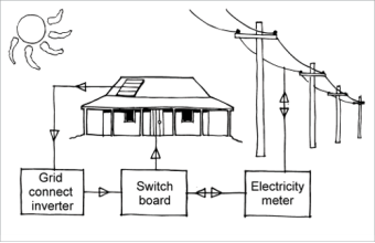
Grid connected systems
A grid connected renewable energy system alters DC electricity from a power source, such as solar panels, to AC mains power and feeds it into the grid. It generally comprises of the energy source, an inverter and a meter.
If there is a mains grid power failure, a grid linked renewable energy system detaches from the grid and energy from solar panels is not available.
Battery banks connected to the grid, with an proper inverter, may work as an uninterruptable power supply to make energy available during a power outage for all or some of the electrical loads in a home or business. Costs are very high and additional components are required; it is technically possible for such a system to enable one of these options:
Grid connected system.
Stand-alone systems
A stand-alone power system is used for delivering energy at local and distant places where it is more cost effective to have on-spot generation than to link to the electricity grid. Stand-alone power systems comprise a power generation source like solar panels or wind turbines, a battery bank, inverter, battery charger and often a fuel generator for back-up power.
Part of the inverter comprises of charge controller. In a stand-alone system, battery banks and inverters are desirable whether the energy comes from solar, wind or micro-hydro.
The exact equipment needed to alter and accumulate energy depending on the energy needs and budget of the user, as well as the offered energy resource and physical constraints of the site.
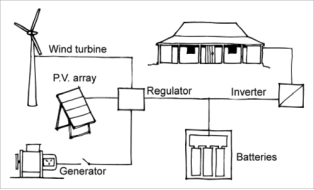
Stand-alone system.
Key takeaways:
1. Batteries and other energy storage devices store energy so that it can be used when required.
2. energy conversion devices such as inverters converts energy from one form to another.
3. An inverter in a grid connected renewable energy system changes direct current (DC) electricity from solar panels or a wind turbine into alternating current (AC) mains power.
a) If a DG set is required for 100% standby, then the entire connected load must be added in HP / kVA. After examining the diversity factor, you can find the correct capacity for the DG set.
Example: Connection load = 650 kW
Diversity factor = 0.54
(Demand / connection load)
Maximum demand = 650 x 0.54 = 350 kW
% Read = 70
Rating setting = 350 / 0.7 = 500 kW
At 0.8 PF, rated = 625 kVA
b) For existing equipment, record current, voltage, and power factor (kWh / kVAh) readings at the system's main busbar every 30 minutes for 2-3 days during this period. The factory should be in normal operation. To find the realistic current needed to run critical equipment, you need to turn off the non-critical load. This gives a fair idea of the current at which the rating of the set can be calculated.
For existing installations: kVA = √3VI
kVA rating = kVA / load factor
Here, load factor = average kVA / maximum kVA
c) For new installations, an approximate way to estimate the capacity of the DG set is to add the full load current of all the proposed loads performed on the DG set. You can then reach the correct capacity by applying the diversity factor according to guidelines obtained from the industry, related processes, and other similar units.
Battery Sizing: Battery sizing requires the following information:
Different manufacturers have different specifications, which makes the comparison confusing while choosing an UPS for a prerequisite Based on the below technical parameters and the relevance for the specific prerequisite the comparison and selection should be done.
Rectifier, inverter and battery are 3 main components of UPS. The rectifier acts as a load to the electrical mains and the subsequent characteristic of the rectifier will choose the nature of upstream infrastructure required.
• Input current distortion (THDI): Harmonics,
• Input power factor,
• Input start-up current,
• Number of wires (3ph or 3ph+Neutral),
• Efficiency (influences global efficiency),
• Maximum output power,
• Input voltage & frequency tolerances
• Generator compatibility
The inverter of the UPS System will be a source for the critical loads associated to the UPS and based on the need of the load the subsequent parameters decides the superiority & capacity of the UPS.
• Nominal apparent power (VA)
• Nominal active power (W)
• load Power factor supporting capability.
• Inverter efficiency (influences global efficiency)
• Distortion of output voltage with different load types
• Max load current crest factor
• Overload, Inrush current and short-circuit capability,
• With or without galvanic isolation
The battery is the core of the UPS system and the choice of battery is more important as it elects the interval of operation in the event of mains failure. The following points has to be assessed to have the right battery configuration.
• KW considered for battery sizing
• End cell voltage
• Ageing factor
(in case of low backup time)
• No of battery bank in parallel
• Design life of the selected battery
• Charging current compatibility with UPS
Key takeaways:
1. Rectifier, inverter and battery are 3 main components of UPS.
2. The inverter of the UPS System will be a source for the critical loads associated to the UPS and based on the need of the load the subsequent parameters decide the superiority & capacity of the UPS.
References:
1. S. L. Uppal and G. C. Garg, “Electrical Wiring, publishers, 2008
2. KB. Raina, “Electrical Design, Estimating & Costing”, New age International, 2007
3. S. Singh and RD. Singh, “Electrical estimating and costing", Dhanpat Ral and Co. 1997. Web site for IS Standards
4. H. Joshi, “Residential Commercial and Industrial System”, McGraw Hill Education, 2008


