Unit - 6
Industrial Electrical System Automation
A programmable logic controller (PLC) is a specialized device used to control machines and processes. It uses programmable memory to store instructions and specific functions, including on / off control, timing, counting, sequencing, arithmetic, and data processing systems.
PLC Components:
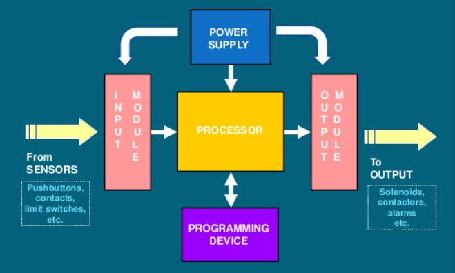
Fig 1 Components of PLC
PLC Operation Sequence: Fig 6.2 shows operation sequence of a PLC
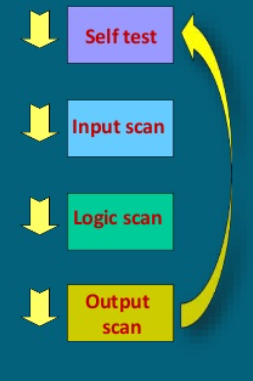
Fig 2 Operation Sequence of PLC
PLC Programming Language:
The most common languages for PLC programming are:
1) Ladder logic
2) Functional block diagram
3) Sequential function chart
4) Boule mnemonic
Ladder Logic: Ladder Logic is the oldest programming language for PLCs. Suitable for expressing combinatorial logic. The main ladder logic symbols represent elements. Contact Break Create a contact relay coil.
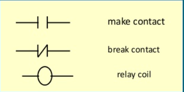
Fig 3 Ladder Logic Symbol
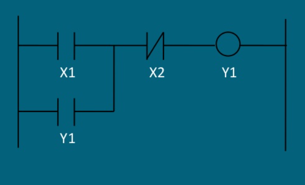
Ladder Logic Example:
Ladder Logic Program for Start/Stop of Motor
Key takeaways:
PLC's role in automation:
Programmable controllers are almost like industrial computers. The PLC can act as a stand-alone unit which will continuously monitor and automate processes, specific machine functions. PLC are often networked. Such a network can control the whole assembly line. PLCs are often adapted to watch and control many sensors and actuators. They process electrical signals and use them to execute pre-programmed commands for nearly any application. PLCs are utilized in industrial automation to enhance reliability, system stability, performance, and minimize the necessity for human operators and therefore the possibility of human error.
Key takeaways:
Today, you can automate almost any business process to some extent. Most can be highly automated. Research firm Gartner shows that 89% of general accounts operations and 72% of financial management and external reporting can be automated.
Business process automation tools make it easy to automate tasks. Often, it includes templates that teams can follow to automate common processes within and across industries, with the following benefits:
1. Operational Efficiency – BPA can increase efficiency by reducing process-related work and reducing salary costs by limiting the need for additional personnel as operations grow. I can do it.
2. Productivity – Speed up your process so you can get things done faster and with fewer iterations.
3. Morale – Relieves workers' monotony and improves employee experience and customer experience. This will further improve the employee experience. “The more time employees spend on the interesting and rewarding aspects of their work, the more productive and satisfying they are, and the more employee retention rates they have,” according to a CIO report.
4. Governance and Management – Improve compliance to prevent businesses from violating regulations and incurring large fines and fees.
5. Cost Reduction – By using time efficiently, companies can choose to increase production without expanding their workforce or reduce salary costs to maintain the same level of production.
6. Employee Assignment – Employees can reassign to jobs that are more suited to their talents. Employees are more satisfied with their work and employers can maximize the benefits of their individual talents.
7. Reduced Human Error – Employee time is not wasted on repetitive low-level work, significantly reducing human data entry and insight errors and improving efficiency.
8. Collaboration – Track project processes, update teams, send reminders, and perform other functions that make collaboration easier and more organized. In addition, BPA relieves employee frustration and frees up time for collaboration. This tends to speed things up, help solve problems, and drive innovation.
9. Improve Insights – Improve your leadership ability to track business process completion and understand process steps. This makes it easier to improve the process and get faster and better business results. BPA also allows readers to dig deeper and analyze more new data for more insight. In addition, standardizing business processes can ensure fairness and eliminate biases that can distort insights.
10. Increased Availability – Make services for employees and customers available more often than if you were also responsible for other manual tasks.
Key takeaways:
Control Overview:
The application of control in manufacturing is expanding very rapidly due to the desire to reduce manufacturing costs and produce higher quality products with better performance. "Control" means automatic control performed by a device called a controller, as opposed to manual control, which requires human intervention. Today, almost all (automated) controllers are implemented using microprocessors, digital signal processing (DSP) chips, programmable logic controllers (PLCs), personal computers (PCs), or workstations.
An important element of control technology is the design of the controller. Common types of controllers include proportional-integral (PI), read lag, model prediction controller (MPC), adaptive controller, neural net controller, and fuzzy logic controller. However, controller design is actually a relatively small part of the overall control problem. Other issues that are very important in control technology are:
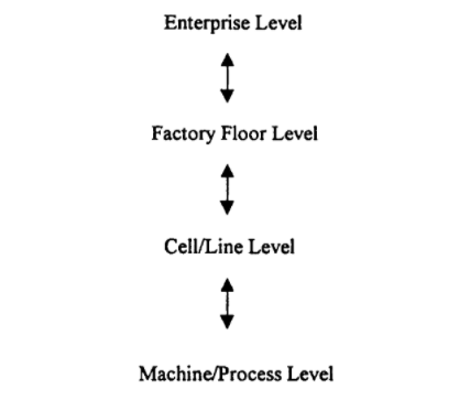
Fig 4 Control is used on each of these levels of a manufacturing system.
Interfaces and communication networks have become very important in control applications.
When applied to manufacturing, controls are used at each of several different levels of the hierarchy shown in Figure 6.4. The top level is the enterprise level, where high-level functions such as finance, controls, and customer relationships are performed. Next is the factory floor level, which contains full production equipment, and then the cell or line level, which contains groups. Of the machine. The lowest level of the hierarchy is the machine / process level, which contains the individual equipment items needed to manufacture the product.
We will first consider the lowest level of control at the machine / process level, and then work on the last part of the text.
General Control Configuration:
Figure 6.5 shows a typical configuration for closed-loop control of a process (or system). Where c1, c2, ..., cm are the control inputs and y1, y2 ... »Yp are the process outputs. This process has a total of m inputs and p outputs. Where m and p are positive integers. In a typical application, m and p can be greater than 10 or greater than 100. The configuration shown in Figure 6.5 is said to be a closed loop type because the process output y is generated by feeding back through the controller. Control input to the process c. Controllers are typically implemented using a microprocessor, DSP chip, PLC, or PC. Controller functionality is determined by control recipes that can be downloaded to the PLC or PC prior to system operation. A reference signal can also be applied to the controller to specify the desired behavior.
The control input ci and the process output y can be continuous or discrete variables. Here, "continuous" means that a variable can take a range of values with real numbers. Examples of continuous variables are voltage, position coordinates, pressure, flow rate, and so on. Continuous variables are also known as analog variables. "Discrete" means that a variable can have only a finite number of different values. An example of a discrete variable is the variable M, which represents the on / off state of a motor, defined by M = 0 when the motor is off and M = 1 when the motor is on.
The control input c and the process output y can be a function of time ¢. In this case, c and y are written as c, (t) and y, (t). A process or system is said to be time-driven if c and y are functions of t. This means that the system is driven by inputs that change values as a result of changes in time ¢ values. If c, (f) and y, (t) are continuous variables, then the system is said to be a continuous variable time-driven system.
Instead of being a function of time t, ci and yi may change their values when an event occurs. In that case, the system is said to be event driven. For example, suppose your system is a switch-controlled motor. Motor status is represented by M. Where M = 1 is when the motor is on, M = 0 is when the motor is off, and the switch status is represented by S. Where S = 0 is S = 1 when the switch is off and when the switch is on. If the input is S and the output is M, then the system (motor and switch) is defined by the equation M = S, so the motor will only turn on if the switch is on. This is an event-driven system because the input S depends on the rotating event toggle on or off. This system is also known as a discrete event system because of the finite number of input and output values.
Many systems that come into play have multiple inputs and outputs, some of which are functions of f, and others that rely on events. Such a system is called a hybrid system. There are few systematic methods for analyzing or designing hybrid systems. However, many researchers are now trying to develop a theory for the study of hybrid systems.
Key takeaways:
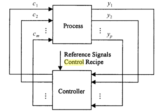
Fig 5 Closed loop control configuration
A metering panel is a type of control panel that is highly needed for home and industrial use to measure power consumption and power consumption rate. These metering panels are the best equipment that can be easily installed and conveniently used in power consumption processes. The weighing panels in these apartments are very easy to install and are equipped with excellent anemometers and galvanometers for calculating current input and output voltage amplitudes.
Panel metering is the key to understanding the energy consumption of homes, buildings and facilities. This is often done by measuring the entire panel at the source or by measuring individual circuits for more sophisticated results (branch circuit monitoring).
Panel meters provide a variety of features such as data logging, internal memory, usage time, and power quality. In addition, the panel meter has various communication options that allow you to collect data remotely. This allows remote easy remote access to a set of power and energy readings for detailed reporting.
Panel metering options include single-phase and three-phase meters, and multi-circuit power meters. All of our measurement options can communicate via a variety of protocols.
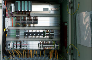
Fig 6 Metering Panel
Key takeaways:
Surveillance Control and Data Acquisition, or simply SCADA, is one of the solutions available for data acquisition, monitoring, and control systems covering large geographic areas. This refers to a combination of data acquisition and telemetry.
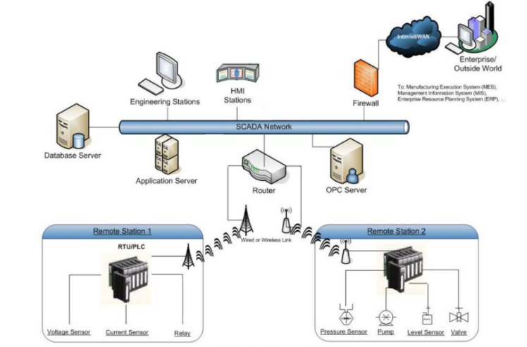
Fig 7 SCADA Network Architecture
SCADA systems are primarily used in equipment or plant monitoring and control system implementations in several industries such as power plants, oil and gas purification, water and waste control, and telecommunications.
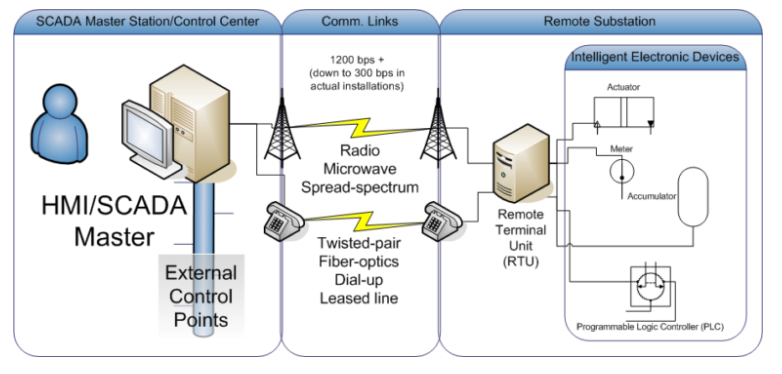
In this system, the number of remote terminal equipment makes measurements at the field or process level of the plant and transfers the data to the SCADA central host computer, allowing more complete process or manufacturing information to be provided remotely.
Typical SCADA system components
The main components of the SCADA system are:
1. Remote Terminal Unit (RTU)
The RTU is a key component of the SCADA system that connects directly to the various sensors, meters, and actuators associated with the control environment.
These RTUs are real-time programmable logic controllers (PLCs) that properly convert remote station information into a digital format for modems, transmit data, convert signals received from the master unit, and control process equipment via actuators and switch box.
2. Master Terminal Unit (MTU)
The central host server or server is called the master terminal unit and is also called the SCADA center. Communicate with multiple RTUs by performing read and write operations during a scheduled scan. In addition, it performs controls, alarms, networking with other nodes, and more.
3. Communications System
Communication networks transfer data between central host computer servers and field data interface devices and control units. The transfer medium can be cable, radio, telephone, satellite, etc., or any combination of these.
4. Operator Workstation
These are computer terminals that consist of standard HMI (Human Machine Interface) software and are networked to a central host computer. These workstations are operator terminals that request information and send it to the host client computer to monitor and control remote field parameters.
5. Distribution System Automation
Modern SCADA systems replace the manual work of performing distribution tasks and manual processes in distribution systems on automated equipment. SCADA maximizes the efficiency of distribution systems by providing features such as real-time view of operations, trend analysis and logging of data, maintenance of required voltage, current and power factor, and generation of alarms.
SCADA improves supply reliability by reducing outages and also provides cost-effective operation of distribution systems. Therefore, distribution SCADA monitors the entire distribution system. The main functions of SCADA can be classified into the following types.
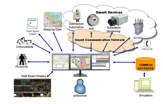
Substation Control Using SCADA
In substation automation systems, SCADA performs operations such as bus voltage control, bus load distribution, circulating current control, overload control, transformer fault protection, and bus fault protection.
The SCADA system continuously monitors the status of various devices in the substation and sends control signals to remote control devices accordingly. It also collects substation history data and generates alarms in the event of an electrical accident or failure.
The figure above shows a typical SCADA-based substation control system. Various input / output (I / O) modules connected to substation equipment collect field parameter data including status such as switches, circuit breakers, transformers, capacitors and batteries, voltage and current magnitudes, and so on. The RTU collects I / O data and transfers Connect to the remote master unit via the network interface module.
The central controller or master unit receives the information, logs it, displays it in the HMI, and generates control actions based on the received data. This central controller is also responsible for trend analysis, centralized alarms, and report generation.
Data historians, workstations, master terminal units, and communication servers are connected by LAN in the control center. Transfers information between the field site and the central controller using a wide area network (WAN) connection using standard protocol communication.
Therefore, implementing SCADA for substation control ultimately improves network reliability and minimizes downtime due to fast transfer of measurements and control commands.
Feeder control using SCADA
This automation includes feeder voltage or VAR control and automatic feeder switching. Feeder voltage control performs voltage regulation and capacitor placement operations, and feeder switching handles remote switching of various feeders, failure detection, failure location identification, operation isolation, and service restoration.
In this system, the SCADA architecture uses wireless fault detection units located at various power stations to continuously check for faults and their location. In addition, it facilitates remote circuit switching and historical data collection of feeder parameters and their status. The following figure shows feeder automation using SCADA.
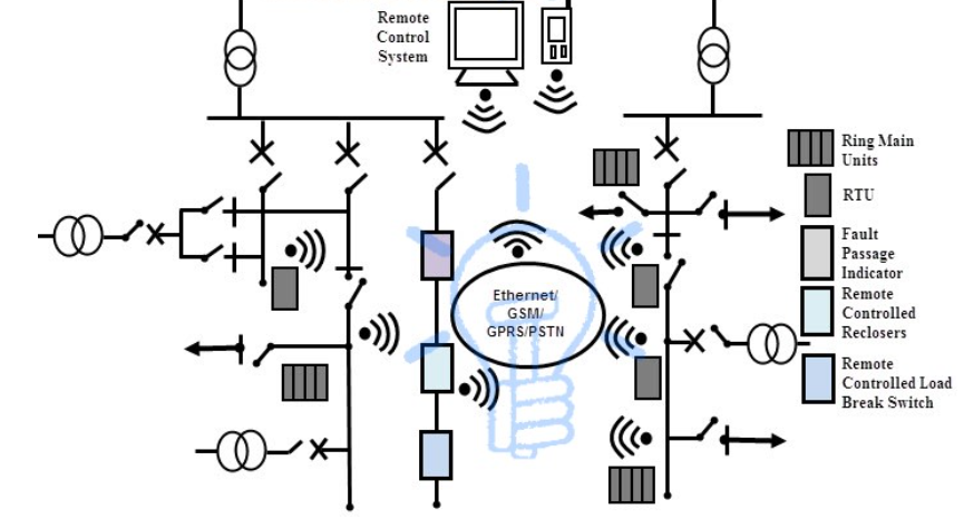
In the typical SCADA network above, various feeders (underground and overhead networks) are automated with modular integrated devices to reduce the number and duration of outages. Underground and overhead fault detection devices provide accurate information about temporary and permanent faults, so preventative and corrective actions can be taken remotely to reduce fault reproducibility.
Ring main unit and remote-control unit (RTU) for underground and overhead networks responsible for maintenance and operation tasks such as remote load switching, capacitor bank insertion, and voltage regulation. The entire network is connected to the communication medium to facilitate remote energy management at the central monitoring station system.
Automation of end-user load control with SCADA
This type of automation on the user side implements features such as remote load control, automatic meter reading, and billing generation. It provides energy consumption by large consumers and proper pricing on demand or per time slot. It also detects tampering or theft of energy meters and disconnects remote services accordingly. Reconnect to the service when the issue is resolved.
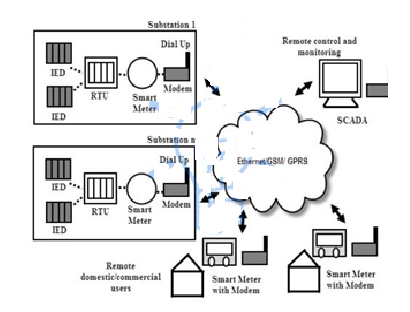
The figure above shows a centralized meter data management system using SCADA. This is a simple and cost-effective solution for automating energy meter data for billing purposes.
Here, a smart meter with a communication unit extracts energy consumption information and makes it available in the central control room and local data storage unit. In the main control room, the AMR control unit automatically acquires, stores and converts all meter data.
Each meter's modem or communication device provides secure two-way communication between the central control and monitoring room and the remote site.
Benefits of implementing a SCADA system for power distribution
Key takeaways:
References:
1. S. L. Uppal and G. C. Garg, “Electrical Wiring, publishers, 2008
2. KB. Raina, “Electrical Design, Estimating & Costing”, New age International, 2007
3. S. Singh and RD. Singh, “Electrical estimating and costing", Dhanpat Ral and Co. 1997. Web site for IS Standards
4. H. Joshi, “Residential Commercial and Industrial System”, McGraw Hill Education, 2008


