Unit - 5
Fault Analysis and Protection Systems
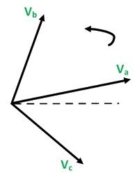
Three Unbalanced Phasors
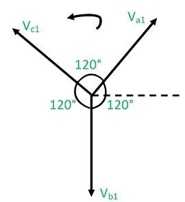
Positive Sequence Components
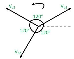
Negative Sequence Components
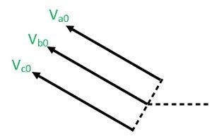
Zero Phase Sequence
Key Takeaway
When the system is not balanced, the currents, voltages and phase impedances are unequal. Such a system is solved by a symmetrical per phase method called the method of symmetrical components or a three-component method.
In the electrical power system, two types of faults occur:
Symmetrical or Balanced Faults
a) Line – Line – Line Fault (L – L – L Fault): The system remains balanced even after the fault occurs. This type of fault occurs rarely, but when it does occur, it is a harsh kind of fault which holds the largest current, which is used to determine the rating of the Circuit Breaker.
b) Line – Line – Ground Fault (L – L – L – G Fault): This fault comprises of all the 3- phases of the system, and occurs among the ground terminal in addition to the 3-phases of the system. The probability of occurrence of this type of fault is 2-3%.
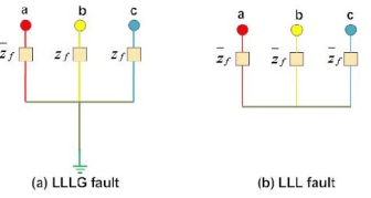
Unsymmetrical or Unbalanced Faults
a) Line to Ground Faults (L-G): It is the most common fault and 75-80% of faults are of this type, causing the conductor to make contact with the ground.
b) Line to Line Faults (L-L): This occurs when two conductors make contact with each other mainly due to swinging of lines during heavy winds. Only 5- 10% of the faults are of this type.
c) Double Line to Ground Faults (LL-G): Both the two lines touch each other through the ground. There is 10% probability of occurrence of such faults.
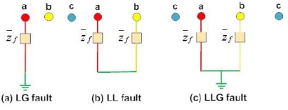
Key Takeaway
When Symmetrical faults occur, the system remains in symmetrical state, but these faults cause very severe damage to electrical power system. Unsymmetrical are also called unbalanced or unsymmetrical faults because their occurrence causes unbalance in the system.
1. Transformers- Sequence Network
Nowadays three-phase transformers are installed since they entail lower initial cost, have smaller space requirements and higher efficiency. The positive sequence series impedance of a transformer equals its leakage impedance. Since a transformer is a static device, the leakage impedance does not change with alteration of phase sequence of balanced applied voltages. The negative Sequence Impedance and Networks of Transformers is also therefore equal to its leakage reactance. Thus, for a transformer

Assuming such transformer connections that zero sequence currents can flow on both sides, a transformer offers a zero-sequence impedance which may differ slightly from the corresponding positive and negative sequence values. It is, however, normal practice to assume that the series impedances of all sequences are equal regardless of the type of transformer.
The zero-sequence magnetizing current is somewhat higher in a core type than in a shell type transformer. This difference does not matter as the magnetizing current of a transformer is always neglected in short circuit analysis.
2. Zero Sequence Networks of Transformers:
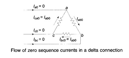
Before considering the zero sequence networks of various types of transformer connections, three important observations are made:
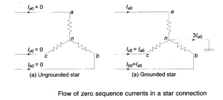
No zero sequence currents can flow in the lines connected to a delta connection as no return path is available for these currents. Zero sequence currents can, however, flow in the legs of a delta—such currents are caused by the presence of zero sequence voltages in the delta connection.
3. Sequence Impedances of Transmission Lines:
A fully transposed three-phase line is completely symmetrical and, therefore, the positive-and negative-sequence impedances of a transmission line are independent of phase sequence and are equal. The expression for inductive reactance, of “Elements of Power Systems” is valid for both positive and negative sequences. When only zero-sequence currents flow in a transmission line, the currents in each phase are identical in both magnitude and phase.
Such currents return partly through ground and the rest through overhead ground wires. The magnetic field due to flow of zero-sequence currents through the transmission lines, ground wires and ground is very different from the magnetic field set up by the flow of positive- or negative-sequence currents. The zero-sequence impedance (particularly the reactance) is about 2 to 4 times the positive sequence impedance.
4. Sequence Impedances and Networks of Synchronous Machines
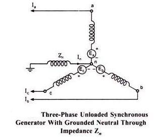
An unloaded synchronous machine (generator or motor) grounded through a reactor of impedance Zn is shown in the figure. Ea, Eb and Ec are the induced emfs in the three phases. When an unsymmetrical fault occurs on the machine terminals, unbalanced currents la, Ib and Ic flow in the lines.
If the fault involves ground, current In flows to neutral to ground via reactance Zn. Depending on the type of fault one or more of line currents may be zero. Unbalanced line currents can be resolved into their symmetrical components.
There are three types of Impedance Network in a synchronous machine, they are as follows-
(a) Positive Sequence Impedance & Network
(b) Negative Sequence Impedance & Network
(c) Zero Sequence Impedance & Network
Key Takeaway
The positive sequence series impedance of a transformer equals its leakage impedance. Since a transformer is a static device, the leakage impedance does not change with alteration of phase sequence of balanced applied voltages. The negative Sequence Impedance and Networks of Transformers is also therefore equal to its leakage reactance.
The knowledge of electrical fault condition is required to deploy proper different protective relays in different locations of electrical power system.
Information regarding values of maximum and minimum fault currents, voltages under those faults in magnitude and phase relation with respect to the currents at different parts of power system, to be gathered for proper application of protection relay system in those different parts of the electrical power system. Collecting the information from different parameters of the system is generally known as electrical fault calculation.
Fault calculation broadly means calculation of fault current in any electrical power system. There are mainly three steps for calculating faults in a system.
If we look at any electrical power system, we will find, these are several voltage levels. For example, suppose a typical power system where electrical power is generated at 6.6 kV then that 132 kV power is transmitted to terminal substation where it is stepped down to 33 kV and 11 kV levels and this 11 kV level may further step down to 0.4 kv.
Hence from this example it is clear that a same power system network may have different voltage levels. So, calculation of fault at any location of the said system becomes much difficult and complicated it try to calculate impedance of different parts of the system according to their voltage level.
This difficulty can be avoided if we calculate impedance of different part of the system in reference to a single base value. This technique is called impedance notation of power system. In other words, before electrical fault calculation, the system parameters, must be referred to base quantities and represented as uniform system of impedance in either ohmic, percentage, or per unit values.
Electrical power and voltage are generally taken as base quantities. In three phase system, three phase power in MVA or KVA is taken as base power and line to line voltage in KV is taken as base voltage. The base impedance of the system can be calculated from these base power and base voltage, as follows,

Per unit is an impedance value of any system is nothing but the radio of actual impedance of the system to the base impedance value.

Percentage impedance value can be calculated by multiplying 100 with per unit value.

Sequence Impedance
(a) Positive Sequence Impedance
The impedance offered by the system to the flow of positive sequence current is called positive sequence impedance.
(b) Negative Sequence Impedance
The impedance offered by the system to the flow of negative sequence current is called negative sequence impedance.
(c) Zero Sequence Impedance
The impedance offered by the system to the flow of zero sequence current is known as zero sequence impedance.
Key Takeaway
Fault calculation broadly means calculation of fault current in any electrical power system. There are mainly three steps for calculating faults in a system.
It is defined as the condition in which the neutral wire of an electrical power system is connected to the ground to protect the system from abnormal fault current that may affect the stability of the system. The neutral may be connected to the earth either solidly or through a resistance of sufficient value so as to materially reduce transients & to give sufficient protection to the devices to operate safely.
Neutral grounding systems are like fuses such that they do not function until something goes wrong in the system and they protect the equipment from damage. Damage comes from two factors: Duration of the fault & Magnitude of the fault. Ground relays trip the breakers and limit the fault duration while neutral grounding resistors prevent large fault current.
Advantages of Neutral Grounding
Methods of Neutral Earthing
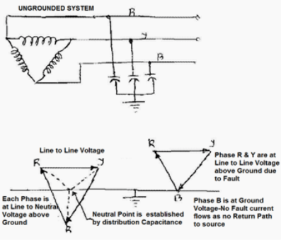
1. Ungrounded Neutral Systems
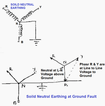
2. Solidly Neutral Grounded Systems
Key Takeaway
It is defined as the condition in which the neutral wire of an electrical power system is connected to the ground to protect the system from abnormal fault current that may affect the stability of the system. The neutral may be connected to the earth either solidly or through a resistance of sufficient value so as to materially reduce transients & to give sufficient protection to the devices to operate safely.
References:
1. Power system Analysis-by John J Grainger William D Stevenson, TMC Companies, 4th edition.
2. The Power System Analysis and Design by B.R. Gupta, Wheeler Publishing
3. Power System Analysis by Hadi Saadat – TMH Edition.
4. Modern Power System Analysis by I.J. Nagaraj and D.P.