Unit 2
The Physical link layer
- Physical layer is related to the transmission of bits across the network (1’s and 0’s)
- Physical and electrical characteristics of network
- Characteristics
How bits are represented on the medium
The Wiring standards for connectors and jacks
Physical topology
Synchronising bits
Bandwidth usage
Multiplexing strategy
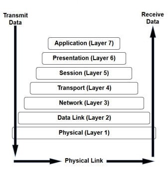
 Bits Transmission
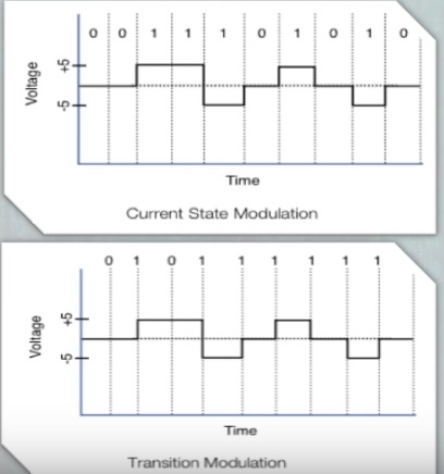
- Electrical voltage (copper wiring) or light (fibre optics) represent 1’s and 0’s (bits)
- Current state (as per diag.) – if 0 volt then, then 0 is represented. If +/- 5 volts, then 1 is represented.
- Transition Modulation (as per diag.) – if it changed during the clock cycle, then 1 is represented otherwise 0.
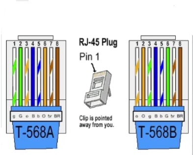
- TIA/EIA-568-B is standard wiring for RJ-45 cables and ports
- Crossover cables use T-568A and T-568B
- Straight-thru cables typically use T-568B on both ends, but T-568A on both ends can also be used
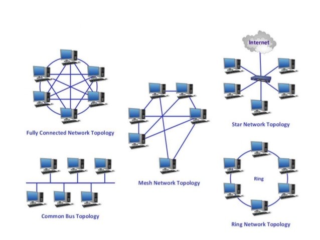
Layer 1 devices view networks from a physical topology perspective
How are the cables connected?
Includes: Bus, Ring, Star, Mesh, Hub-and-Spoke
Bus Topology ->A bus topology is for a Local Area Network (LAN) in which all the nodes are connected into a single cable. The cable in which the nodes are connected is called a "backbone". If the backbone broken, the entire segment fails.
Ring Topology -> A ring topology is a configuration in the network in which device connections will create a circular data path. Each networked device is connected to one another, like points on a circle. Together, devices in a ring topology are called a ring network.
Star Topology -> A star topology is for a Local Area Network (LAN) in which all the nodes are individually connected to one central connection point, like a hub or a switch. A star requires more cable than e.g. a bus, but the benefit of star topology is that if a cable fails, only one node will be brought down.
Mesh Topology -> A mesh topology can be of 2 types full mesh topology or partially connected mesh topology.
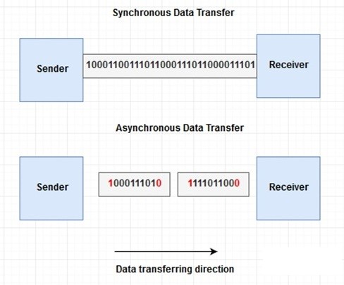
Synchronous -> uses a reference clock to coordinate the transmissions by both sender and receiver
Asynchronous -> Uses start bits and stop bits to indicate when transmission occur from sender to receiver
Broadband-> Divides bandwidth into separate channels example cable TV
Baseband -> uses all available frequency on a medium (cable) to transmit data reference clock to coordinate the transmissions by both sender and receiver example Ethernet
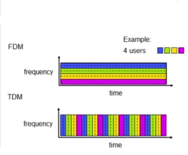
Time division multiplexing -> each session takes turns using time slots to share the medium between all users
Statistical time division multiplexing -> more efficient version of TDM, it dynamically allocates time slots on an as needed basis instead of statistically assigning
Frequency division multiplexing -> Medium is divided into various channels based on frequencies and each session is transmitted over a different channel example broadband
Definition
It is defined as the physical medium through which the signals are transmitted. It is also known as Bounded media.
Types ofGuided Transmission Media
Twisted pair:
Twisted pair is a physical media made up of a pair of cables twisted with each other. A twisted pair cable is cheaper than other transmission media. It is easy to install twisted pair cable, and it is a lightweight cable. The frequency range for twisted pair cable is from 0 to 3.5 KHz.
A twisted pair has two insulated copper wires which is arranged in a regular spiral pattern.
The degree of reduction in noise interference is determined by the number of turns per foot. Increasing the number of turns per foot decreases noise interference.

Types of Twisted pair:
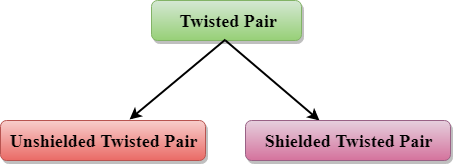
Unshielded Twisted Pair:
An unshielded twisted pair is broadly used in telecommunication. Following are the categories of the unshielded twisted pair cable:
- Category 1: Used for telephone lines which have low-speed data?
- Category 2: It can support up to 4Mbps.
- Category 3: It can support up to 16Mbps.
- Category 4: It can support up to 20Mbps. Therefore, it can be used for long-distance communication.
- Category 5: It can support up to 200Mbps.
Advantages of Unshielded Twisted Pair:
- It is cheap.
- Installation of the unshielded twisted pair is easy.
- It can be used for high-speed LAN.
Disadvantage:
- This cable is only used for shorter distances due to attenuation.
Shielded Twisted Pair
A shielded twisted pair is a cable which contains the mesh surrounding wire allows the higher transmission rate.
Characteristics of Shielded Twisted Pair:
- The cost of the shielded twisted pair cable is not very high and not very low.
- An installation of STP is easy.
- Higher capacity as compared to the unshielded twisted pair cable.
- It has a higher attenuation.
- It is shielded which provides the higher data transmission rate.
Disadvantages
- It is very expensive as compared to that of UTP and coaxial cable.
- It has a higher attenuation rate.
Coaxial Cable
- Coaxial cable is more commonly used transmission media, for instance, TV wire is usually a coaxial cable.
- The name of the cable is coaxial as it contains two conductors parallel to each other.
- The frequency is higher as compared to twisted pair cable.
- The inner conductor of the coaxial cable is made up of copper, and the outer conductor is made up of copper mesh. The middle core is made up of non-conductive cover that separates the inner conductor from the outer conductor.
- The middle core is only responsible for data transferring whereas the copper mesh prevents from the EMI (Electromagnetic interference).

Coaxial cable is of two types:
- Baseband transmission: It is defined as the process of transmitting a single signal at high speed.
- Broadband transmission: It is defined as the process of transmitting more than one signal simultaneously.
Advantages of Coaxial cable:
- The data can be transmitted at high speed.
- It has better shielding than twisted pair cable.
- Higher bandwidth.
Disadvantages of Coaxial cable are as follows:
- It is more expensive than twisted pair cable.
- If any fault occurs in the cable causes the failure in the entire network.
Fibre Optic
- Fibre optic cable is a cable that uses electrical signals for communication.
- Fibre optic is a cable that holds the optical fibres coated in plastic that are used to send the data by pulses of light.
- The plastic coating protects the optical fibres from heat, cold, electromagnetic interference from other types of wiring.
- Fibre optics provides faster data transmission than copper wires.
Diagrammatic representation of fibre optic cable:

Basic elements of Fibre optic cable:
- Core: The optical fibre consists of a narrow strand of a glass or a plastic called core. A core is light transmission area of fibre. The more the area of the core, the lighter will be transmitted into the fibre.
- Cladding: The concentric layer of glass is known as cladding. The main functionality of the cladding is to provide the lower refractive index at the core interface as they cause the reflection within the core so that the light waves are transmitted through the fibre.
- Jacket: The protective coating consisting of plastic is known as a jacket. The main purpose of a jacket is to preserve the fibre strength, absorb shock and extra fibre protection.
The advantages of fibre optic cable over copper are:
- Greater Bandwidth: The fibre optic cable provides more bandwidth as compared to copper cable. Therefore, the fibre optic cable carries more data as compared to copper cable.
- Faster speed: Fibre optic cable carries the data in the light format. This allows the fibre optic cable to carry the signals at a very high speed.
- Longer distances: The fibre optic cable carries the data at a very long distance as compared to copper cable.
- Better reliability: The fibre optic cable is more reliable than the copper cable as it is immune to any temperature changes while it can cause obstruct in the connectivity of copper cable.
- Thinner and Sturdier: Fibre optic cable is thinner and lighter in weight so it can withstand more pull pressure than copper cable.
- Physical layer is concern with the transmission of raw bit stream over physical medium
- The standards of physical layer deals with mechanical, electrical and procedural characteristics to access the physical medium
- Some parts of the physical layer are completely related to that of the medium and others are independent of the medium useful thinking physical layer as two sublayers
–“Medium dependent sublayer” which specifies the medium, physical connectors which are related to mechanical and electrical characteristics
–“Medium independent sublayer”: covers line coding – how to transmit 0 and 1bits; synchronisation – the sender and the receiver clocks should be synchronised to know which is the start/end of a bit, usually by organising block of bits into a frame; other issues are not directly linked to the medium
References:
- Data Communication & Networking by Forouzan, Tata McGraw Hill.
- Computer Network, 4e, by Andrew S. Tenenbaum, Pearson Education/ PHI.
- Data Communication and Computer Networks, by Prakash C.Gupta, PHI.
- Networking Ali-in-one Desk Reference by Doug Lowe, Wiley Dreamtech
- Computer Networking: A Top-Down Approach featuring the Internet, 3e by James F.Kurose.
- Computer Network by Godbole, Tata McGraw Hill.
- Computer Networking, by Stanford H. Rowe, Marsha L. Schuh