Unit 3
The Data Link Layer
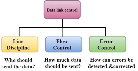
Data Link Control is the service provider by the Data Link Layer which provides the reliable data transfer for the physical medium.
For example, in the half-duplex transmission mode, one device can transmit the data at one time. If both the devices at the end of the links transmit the data parallel, they will collide and leads to the loss of the information. The Data link layer can provide the coordination among the devices so no collision occurs.
Three functions of data link layer are as follows:
- Line discipline
- Flow Control
- Error Control
- In the OSI model, from the top it is the fourth layer and from the bottom it is the second layer.
- The communication channel which can connect the adjacent nodes is called links, and in order to move the datagram from source to destination, the datagram must move across an individual link.
- The main responsibility of this Layer is to transfer the datagram across individual link.
- The Data link layer protocol defines the format of the packet which is exchanged across the nodes as well as the actions for instance Error detection, retransmission, flow control, and random access.
- The Data Link Layer protocols are as follows such as Ethernet, token ring, FDDI and PPP.
- An important characteristic of a Data Link Layer is that datagram which can be handled by very different link layer protocols on the different links in a path. For instance, the datagram is handled by Ethernet on the first link, PPP on the second link.
Following services are provided by the Data Link Layer as follows:
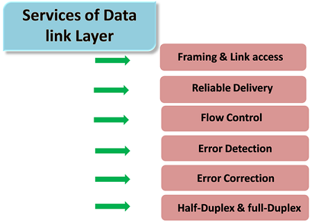
- Framing & Link access: Data Link Layer protocols encapsulate each of the network frames within a Link layer frame before the transmission takes place across the link. A frame consists of that of a data field in which network layer datagram is inserted and that of a number of data fields. It specifies the structure of frame as well as a channel access protocol by which the frame is to be transmitted over link.
- Reliable delivery: Data Link Layer provides a reliable delivery service that is it transmits the network layer datagram without any of the error. A reliable delivery service has to be accomplished with transmissions and acknowledgements. A data link layer mainly provides that of the reliable delivery service over the links as they have the higher error rates and they should be corrected locally, link at which an error occurs rather than it is forcing to retransmit data.
- Flow control: A receiving node can receive the frames at a very fast rate than it can process the frame. Without flow control, the receiver's buffer can be overflow, and the frames can get lost. To overcome this type of problem, the data link layer uses the flow control to which it prevents the sending node on one side of the link from overwhelming to the receiving node on another side of that link.
- Error detection: Errors can be introduced by the signal attenuation and noise. Data Link Layer protocol provides a mechanism to that it detects one or more errors. This is achieved by adding one of the error detection bits in the frame and then receiving node which can perform an error check.
- Error correction: Error correction is way similar to the Error detection, except to that of the receiving node not only detects the errors but also it can determine where the errors have occurred in the frame.
- Half-Duplex & Full-Duplex: In a Full-Duplex mode, both of the nodes that can transmit the data at the same time. In a Half-Duplex mode, only one of the node can transmit the data at the same time.
Frames are units of digital transmission which is particularly in computer networks and telecommunications. Frames are comparable to the packets of energy called photons in case of light energy. Frames are continuously used in the Time Division Multiplexing process.
Framing is a point-to-point connection between two of the computers or the devices consists of a wire in which data can be transmitted as a stream of bits. However, these bits must be framed into the discernible blocks of the information. Framing is that of the function of the data link layer. It provides a way to a sender to transmit set of bits that are meaningful to the receivers end. Ethernet, token ring, frame relay, and other data link layer technologies have their own frame structures. Frames have headers that contain information such as error-checking codes.
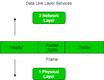
At data link layer, it gets message from the sender and then provide it to receiver by providing the sender’s and the receiver’s address. The advantage of using frames is that the data is broken up into that of recoverable chunks that can be easily checked for corruption.
Problems in Framing –
- Detecting start of the frame: When frame is transmitted, every station must be able to detect it. Station detects frames by looking out for special sequence of bits that marks the beginning of the frame that is SFD (Starting Frame Delimiter).
- How does station detect a frame: Every station listen to the link for SFD pattern through that of sequential circuit? If SFD is detected, sequential circuit alerts the station. Station then checks destination address to accept or reject the frame.
- Detecting end of frame: When to stop reading the frame.
Framing is of two types:
1. Fixed size – Fixed size frame and then there is no need to provide boundaries to the frame, length of the frame acts as a delimiter.
- Drawback: It suffers from internal fragmentation if data size is less than that of frame size
- Solution: Padding
2. Variable size – In this there is needed to define the end of frame as well as beginning of the next frame to distinguish. This can be done in two of the ways:
- Length field – We can introduce a new field which is length field in the frame to indicate the length of the frame. Used in Ethernet (802.3). The problem with this is that sometimes the length field might get corrupted.
- End Delimiter (ED) – We can introduce an ED (pattern) to indicate the end of the frame. Used in Token Ring. The problem with this is that ED can occur in the data. This can be solved by:
1. Character/Byte Stuffing: It is used when frames consist of character. If the data contains ED then the byte is stuffed into the data to diffentiate it from that of ED.
Let ED = “$” –> if data contains ‘$’ anywhere, it can be escaped using ‘\O’ character.
–> if data contains ‘\O$’ then, use ‘\O\O\O$'($ is escaped using \O and \O is escaped using \O).
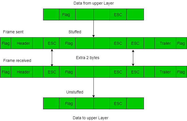
Disadvantage – It is more costly and obsolete method.
2. Bit Stuffing: Let ED = 01111 and if data = 01111
–> Sender stuffs a bit to break the pattern i.e. here appends a 0 in data = 011101.
–> Frame is received by the receiver.
–> If data contains 011101, receiver removes the 0 and reads the data.
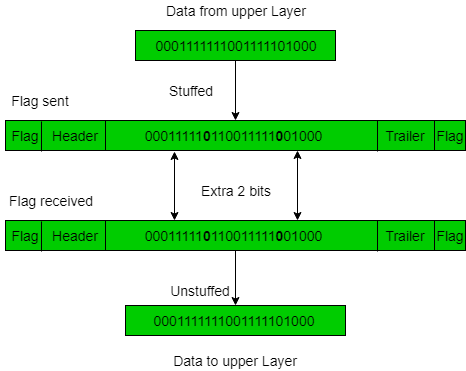
Examples –
- If Data –> 011100011110 and ED –> 01111 then, find data after bit stuffing?
–> 01110000111010
- If Data –> 110001001 and ED –> 1000 then, find data after bit stuffing?
–> 11001010011
Flow control is a technique that will allows two or more stations working at different speeds that will communicate with each other. It is a set of measures that is taken to regulate the amount of data that a sender will sends so that a very fast sender does not overwhelm to that of a slow receiver. In data link layer, flow control will restricts the number of frames that the sender can send before it will waits for an acknowledgment from that of the receiver.
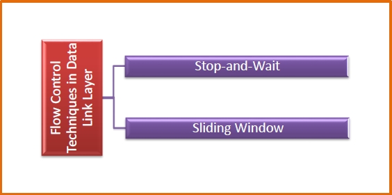
Flow Control Techniques in Data Link Layer are given below
Data link layer uses feedback based flow control mechanisms. The two main techniques are −
Stop and Wait
This protocol involves the following transitions that are −
- The sender willsend a frame and then waits for acknowledgment.
- Once the receiver will receive the frame, it sends again an acknowledgment frame back to the sender.
- On again receiving the acknowledgment frame, the sender then understands that the receiver is ready to accept the next frame. So it send the next frame in a queue.
Sliding Window
This protocol will improve the efficiency of stop and waits protocol by allowing more than one frames to be transmitted before receiving the acknowledgment.
The working principle of this protocol can be described as given below −
- Both the sender and the receiver have limited sized buffers known as windows. The sender and the receiver willagree upon the number of frames that is to be sent based upon the buffer size.
- The sender sends more than one frames in a sequence, without waiting for any acknowledgment. When its sending window is filled, it will wait for acknowledgment. On receiving acknowledgment, it advances the window and transmits the next frames, according to the number of acknowledgments received
When a data is transmitted from one of the device to another device, the system does not guarantee whether the data will received by the device is identical to that of the data transmitted by another device. An Error is a situation when message received at the receiver end is not equal to message transmitted.
Types of Errors
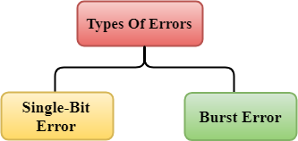
Errors can be classified into two types:
- Single-Bit Error
- Burst Error
Single-Bit Error:
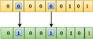
The only one bit of that of a given data unit is changed from 1 to 0 or from 0 to 1.

In the above figure, the message which is sent is corrupted as single-bit that is 0 bit is changed to 1.
Single-Bit Error does not appear more likely to be in Serial Data Transmission. For instance, Sender sends the data at 10 Mbps, this means that the bit lasts only for 1? S and for a single-bit error to occurred, a noise must be more than 1? S.
Single-Bit Error mainly occurs in Parallel Data Transmission. For instance, if eight wires are used to send the eight bits of a byte, if one of the wires is noisy, then single-bit is corrupted per byte.
Burst Error:
The two or more bits are changed from 0 to 1 or from 1 to 0 are called Burst Error.
The Burst Error is determined from the very first corrupted bit to the last corrupted bit.
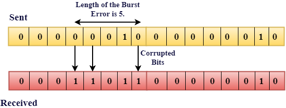
The duration of that of the noise in Burst Error is more than the duration of that of the noise in Single-Bit.
Burst Errors are most likely to occur in that of the Serial Data Transmission.
The number of affected bits depends on that of the duration of the noise and the data rate.
The most popular Error Detecting Techniques are as follows:
- Single parity check
- Two-dimensional parity check
- Checksum
- Cyclic redundancy check
Single Parity Check
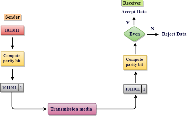
- Single Parity checking is the very simple mechanism and is inexpensive to detect the errors.
- In this technique, a redundant bit is also called as a parity bit which is appended at the end of that data unit so that the number of 1s becomes the even. Therefore, the total number of transmitted bits can be 9 bits.
- If the number of 1s bits is the odd one, then parity bit 1 is appended and if the number of 1s bits is even one, then parity bit 0 is appended at that of the end of the data unit.
- At the receiving end, the parity bit is then calculated from received data bits and then compared with that of received parity bit.
- This technique generates the total number of 1s even, so it is called even-parity checking.
Drawbacks of Single Parity Checking
- It can only detect single-bit error which is very rare.
- If the bits are interchanged, then it cannot detect the errors.
Two-Dimensional Parity Check
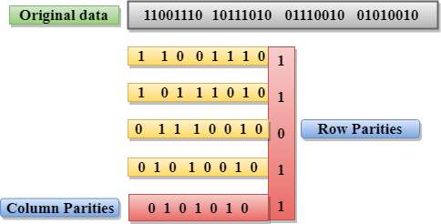
- Performance is to be improved by using the Two-Dimensional Parity Check which organizes the data in the form of table.
- Parity check bits are computed for each of the row, which is equivalent to the single-parity check.
- In Two-Dimensional Parity check, a block of bits has to be divided into rows, and the redundant row of bits is then added to the whole block.
- At the receiving end, the parity bits are then compared with the parity bits computed from that of the received data.
Drawbacks of 2D Parity Check
- If two bits in one of the data unit are corrupted and when two bits exactly the same position in another data unit is also corrupted, then 2D Parity checker will not be able to detect the error occurred.
- This technique cannot be used to detect that of 4-bit errors or more in some cases.
Checksum
A Checksum is an error detection technique based on concept of redundancy.
It is divided into two parts that is:
Checksum Generator
A Checksum is generated at that of sending side. Checksum generator then subdivides the data into equal segments of n bits each, and all of these segments are added together by using one's complement arithmetic. The sum is complemented and appended to the original data, called checksum field. The extended data is then transmitted across the network.
Suppose L is the total sum of the data segments, then the checksum would be? L
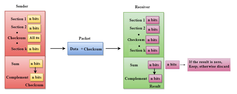
- The Sender follows the given steps:
- The block unit is divided into k sections, and each of n bits.
- All the k sections are added together by using one's complement to get the sum.
- The sum is complemented and it becomes the checksum field.
- The original data and that of checksum field are sent across the network.
Checksum Checker
A Checksum is verified at that of receiving side. The receiver then subdivides the incoming data into its equal segments of n bits each, and all these segments are then added together, and then this sum is complemented. If the complement of the sum is zero, then the data is accepted otherwise data is rejected.
- The Receiver follows the given steps:
- The block unit is divided into k sections and then each of n bits.
- All the k sections are added together by using one's complement algorithm to get the sum.
- The sum is complemented.
- If the result of the sum is zero, then the data is accepted otherwise the data is discarded.
Cyclic Redundancy Check (CRC)
CRC is a redundancy error technique which is used to determine the error.
Following are the steps used in CRC for error detection are as follows:
- In CRC technique, a string of n 0s is appended to that of the data unit, and this n number is less than the number of bits in a predetermined number, which is known as division which is n+1 bits.
- Secondly, the newly extended data is then divided by a divisor using a process which is known as binary division. The remainder generated from this division called CRC remainder.
- Thirdly, the CRC remainder that replaces the appended 0s at the end of the original data. This newly generated unit is then sent to the receiver.
- The receiver then receives the data followed by the CRC remainder. The receiver will then treat this whole unit as a single unit, and then it is divided by the same divisor that was used to find the CRC remainder.
If the resultant of this division is zero that means that it has no error, and the data is acceptable.
If the resultant of this division is not zero that means that the data contains an error. Therefore, the data is discarded.
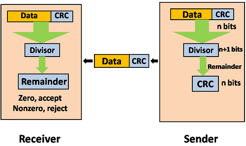
Let's understand this concept through an example:
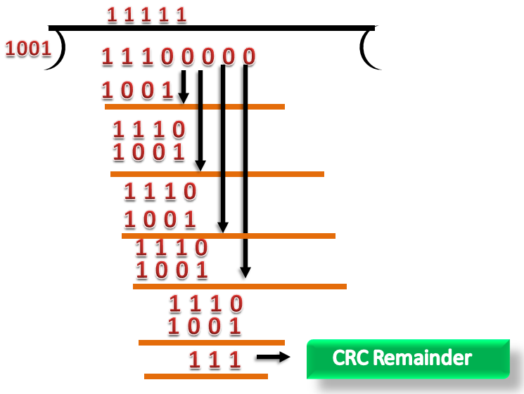
Suppose the original data is 11100 and divisor is 1001.
CRC Generator
- A CRC generator uses a modulo-2 division. Firstly, three zeroes are appended at the end of the data as the length of the divisor is 4 and we know that the length of the string 0s to be appended is always one less than the length of the divisor.
- Now, the string becomes 11100000, and the resultant string is divided by the divisor 1001.
- The remainder generated from the binary division is called CRC remainder. The generated value of the CRC remainder is 111.
- CRC remainder replaces the appended string of 0s at the end of the data unit, and the final string would be 11100111 which is sent across the network.
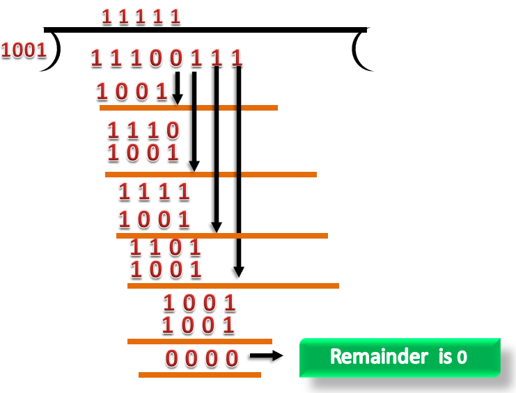
CRC Checker
- The functionality of the CRC checker is similar to that of CRC generator.
- When the string 11100111 is received at the receiving end, then CRC checker performs the modulo-2 of division.
- A string is divided by the same divisor, i.e., 1001.
- In this case, CRC checker generates the remainder of zero. Therefore, the data is then accepted.
Characteristics
- It is used in Connection-oriented communication.
- Error and flow control is also mentioned
- It is used in Data Link layer as well as Transport Layers also
- Stop and Wait ARQ mainly deals with Sliding Window Protocol concept with Window Size 1
Useful Terms:
- Propagation Delay: Amount of time taken by a packet to make a physical journey from one router to that of another router.
Propagation Delay = (Distance between routers) / (Velocity of propagation)
- Roundtrip Time (RTT) = 2* Propagation Delay
- Timeout (TO) = 2* RTT
- Time To Live (TTL) = 2* Timeout. (180 seconds is Maximum TTL)
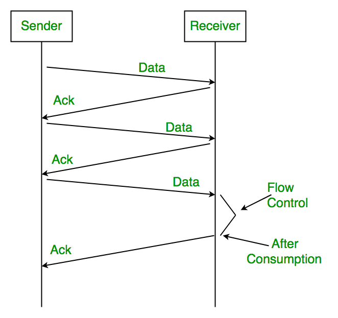
Simple Stop and Wait
Sender:
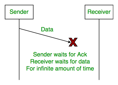
Rule 1) one data packet is sent at one time.
Rule 2) send the next data packet only after acknowledgement is received from previous.
Receiver:
Rule 1) Acknowledgement is sent after receiving and consuming of data packet.
Rule 2) after consuming packet acknowledgement need to be sent again (Flow Control)
Problems:
1. Lost Data
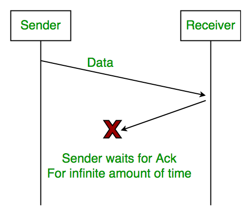
2. Lost Acknowledgement:
3. Delayed Acknowledgement/Data: After session is timeout on sender side, a long delayed acknowledgement will be wrongly considered as acknowledgement of some of the other recent packet.
Stop and Wait ARQ (Automatic Repeat Request)
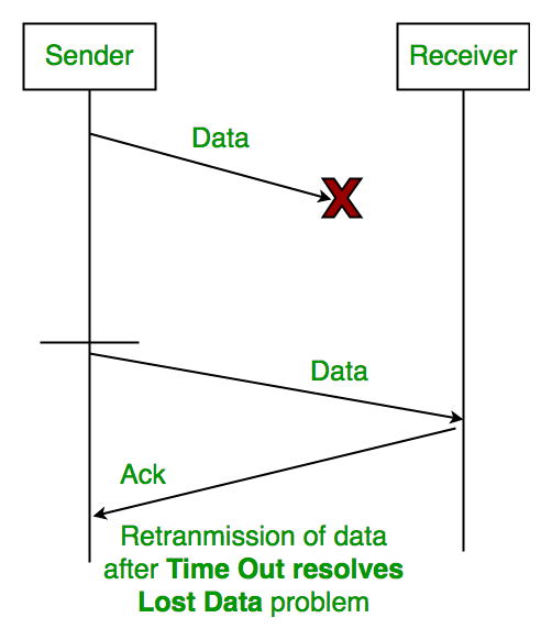
Above 3 problems are resolved by Stop and Wait ARQ (Automatic Repeat Request) that does both parts error control and flow control.

1. Time Out:
2. Sequence Number (Data)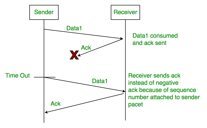
3. Delayed Acknowledgement:
This can be resolved by introducing sequence number for acknowledgement also.
There is much type of flow control protocols-
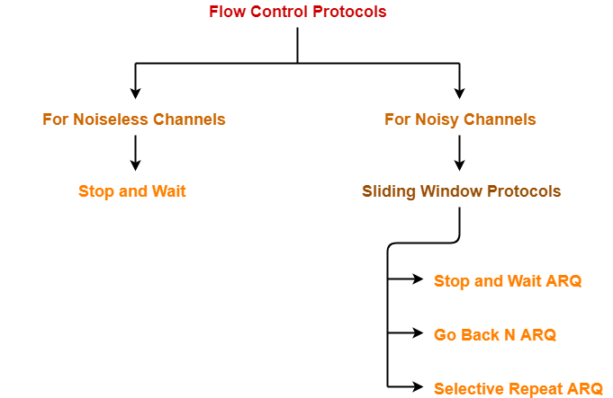
Sliding Window Protocol-
- IT is a flow control protocol.
- Sliding window protocol allows the sender to send more than one frames before needing the acknowledgements.
- Sender will slide its window when receiving the acknowledgements for that of the sent frames.
- This will allow the sender to send more than one frames.
- It is called this because it will involve the sliding of sender’s window.
Maximum number of frames that sender can send without acknowledgement Is equal to Sender window size |
Optimal Window Size-
In a sliding window protocol, optimal sender window size is equal to 1 + 2a |
Derivation-
We know,
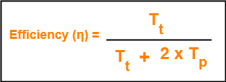
To get 100% efficiency, we must have-
η = 1
Tt / (Tt + 2Tp) = 1
Tt = Tt + 2Tp
Thus,
- To get 100% efficiency, transmission time must be Tt + 2Tp instead of Tt.
- This means sender must send the frames in waiting time too.
- Now, let us find the maximum number of frames that can be sent in time Tt + 2Tp.
We have-
- In time Tt, sender sends one frame.
- Thus, In time Tt + 2Tp, sender can send (Tt + 2Tp) / Tt frames i.e. 1+2a frames.
Thus, to achieve 100% efficiency, window size of the sender must be 1+2a.
Required Sequence Numbers-
Each sending frame has to be given a unique sequence number.
- Maximum number of frames that can be sent in a window = 1+2a.
- So, minimum number of sequence numbers required = 1+2a.
To have 1+2a sequence numbers, Minimum number of bits required in sequence number field = ⌈log2(1+2a)⌉ |
NOTE-
- When minimum number of bits is asked, we take the ceil.
- When maximum number of bits is asked, we take the floor.
Choosing a Window Size-
The size of the sender’s window is bounded by-
1. Receiver’s Ability-
- Receiver’s ability to process the data bounds the sender window size.
- If receiver cannot process the data fast, sender has to slow down and not transmit the frames too fast.
2. Sequence Number Field-
- Number of bits available in the sequence number field also bounds the sender window size.
- If sequence number field contains n bits, then 2n sequence numbers are possible.
- Thus, maximum number of frames that can be sent in one window = 2n.
For n bits in sequence number field, Sender Window Size = min (1+2a , 2n) |
Implementations of Sliding Window Protocol-

- Go back N Protocol
- Selective Repeat Protocol
Efficiency-
Efficiency of any flow control protocol may be expressed as-
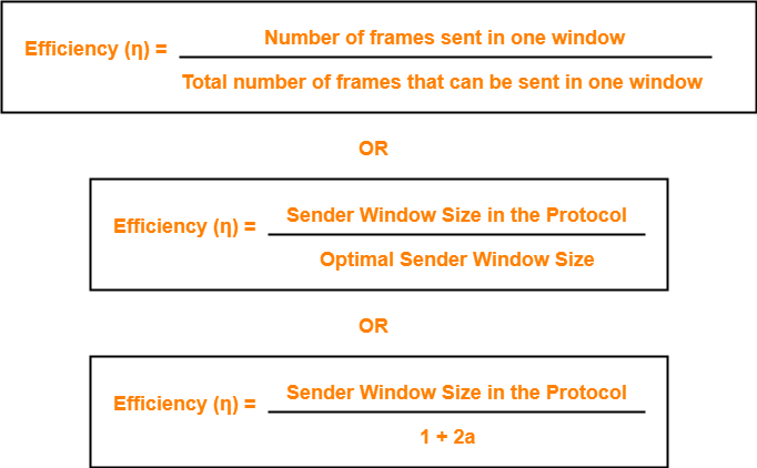
Example-
In Stop and Wait ARQ, sender window size = 1.
Thus,
Efficiency of Stop and Wait ARQ = 1 / 1+2a
The most important protocol in the internet is Transmission Control Protocol. TCP provides full transport layer service to applications and generates a virtual circuit between the sender and the receiver that is active for the duration of transmission. TCP segment consists of TCP header, TCP options and data that segment transports.
Sequence Numbers –
The 32 bit sequence number field defines the number assigned to the first byte of data contained in this segment. Stream transport protocol is TCP. Each byte to be transmitted is numbered to ensure the connectivity. Each party uses a Random number generator to create initial sequence number (ISN) during connection establishment, which is usually different in each direction. 32 bit is sequence number of TCP. So it has finite (from 0 to (232-1) = 4 Giga sequence numbers) and it means we will be able to send only 4GB of data with unique sequence number not more than that. It helps with the allocation of a sequence number that does not conflict with other data bytes transmitted over a TCP connection. An ISN is unique to each connection and separated by each device.
To utilize the available bandwidth more efficiently a technique is used which is Piggybacking in networking. The host does not send the acknowledgement to the received frame but waits for some time and includes the acknowledgement in the next outgoing packet/frame.
Consider a 2 way communication between two hosts A and B, in which A sends some data to B and in response B sends some data to A.
Initially, A sends some data to B, on receiving this, B has to send an acknowledgement to A.
This acknowledgement can be sent in two ways
- B sends the acknowledgement to A immediately and in the next packet it sends the data to A. Thus sending two packets.
- B waits for some time and sends the acknowledgement along with the response/data as one packet.
The second approach of sending both data and acknowledgement in the same packet us known as piggybacking.
Advantages
- The Network bandwidth is better utilized.
Disadvantages
- If the B waits for a long time before sending the acknowledgement, A may retransmit the packet
Data link management is used to make easy the configuration and management of optical network device. These types of devices are interconnected by thousands of data bearing links.

The channel access protocol which serves to coordinate the frame transmissions in many of the nodes; Frame headers also include fields for a node's so-called physical address, which is completely distinct from the node's network layer (for example, IP address).
References:
- Data Communication & Networking by Forouzan, Tata McGraw Hill.
- Computer Network, 4e, by Andrew S. Tenenbaum, Pearson Education/ PHI.
- Data Communication and Computer Networks, by Prakash C.Gupta, PHI.
- Networking Ali-in-one Desk Reference by Doug Lowe, Wiley Dreamtech
- Computer Networking: A Top-Down Approach featuring the Internet, 3e by James F.Kurose.
- Computer Network by Godbole, Tata McGraw Hill.
- Computer Networking, by Stanford H. Rowe, Marsha L. Schuh