Unit 1
Introduction
A control system is a set of mechanical or electronic devices which control the other devices. In control system behaviours of the system is desired by differential equations
Classification of control system
(1) Open Loop control System:-
This is the loop of control system without any feedback. In this the control action is not dependent on the desired output.
 Fig. 1 open loop control system
Example of open Loop systems are The traffic signals, Automatic washing machine and in fields control d.c motor.
(2) Closed Loop control system:-
This is a type of control system with feedback In this type of system The control action is dependent on the desired output.
 Fig 2. Closed Loop control system
The error signal is again fed to controller to the error and get desired output.
Comparisons between open Loop and Closed Loop system
Open Loop System | Closed Loop system |
1.It does Not have any feedback. | 1. This system comprise of feedback |
2.As no feedback so easier to build. | 2.As it has feedback so difficult to build |
3.Theaccuracy of this system depends on the calibration of input. | 3.They are accuracy because of the feedback. |
4.Open Loop system are more stable. | 4.In closed Loop system stability depends on system components. |
5.optimization is not possible | 5. Optimization is possible |
6.These system are not reliable. | They are more reliable |
Transfer Function:-
The transfer function of a linear time invariant system is the ration of Laplace transform of the output to input.
(a) For open Loop system

G(s) = c(s)/R(s) -------(1)
 (b) For closed Loop system
+
-
G(s) – forward amplification
H(s) _ Reverse amplification
Above system is with negative feedback.
Positive feedback is used only in oscillators and other use is not known as discussing only negative feedback.
[ R(s) – c(s) H (S) ] G(s) = c(s)
R (s) G(s) = [1+G(s) H(s)] c(s)
C(s)/R(S) = G(S)/1+G(s) H(s)
S0, the transfer function of closed Loop system is
C(s)/ R(S) = G(s)/ 1+G(S) H(S) --------(2)
If numerator of above equation (2) is equalized to zero we get zeros of closed Loop Transfer function [G(S) = 0]
If dominator of equation (2) is equaled to zero we get polls of the closed loop transfer function [ 1+G(s) H(S) = 0]
1+ G(S) H(s) = 0 [ characteristic Equation]
Servomechanism is also called servo which is a device usually error sensing device connected as a feedback element to correct the action of a mechanism. Here instead of controlling a device by variable input signal, the device is controlled by feedback signal.
The input signal applied to such systems generate the required output which is compared again to the input signal. If the device achieves its desired output, there will be no longer the logical difference between the two signals. Hence, the primary task of servomechanism is to maintain the output of a system at the desired value in the presence of disturbances.
Types of Servomotors:-
(a). A.C. Servomotors
(b). D.C. Servomotors
(a). A.C.Servomotors:-
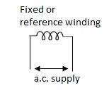
A.C servomotor is a two-phase ac induction motor. There are two windings in this motor, one is fixed or reference winding is supplied with a fixed voltage and frequency from a constant voltage source. Second winding is control winding with variable supply voltage of same frequency as reference winding but having a phase displacement of 900 electrical. A flux is induced due to the phase change which cuts the conducting bars of rotor and causes a time varying current, this current produces a time varying flux and reacts with the stator flux causing the rotor to rotate.
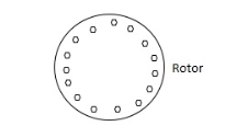
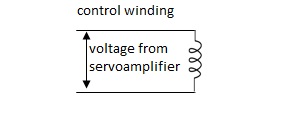
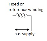
The rotor of A.C. Servomotos are of two types,
(a). Squirrel Cage Rotor
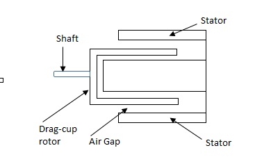
(b). Drag cup type rotor
(a). Squirrel cage rotor :- They have high resistance as the rotor is having large length and small diameter. The air gap here is kept small.

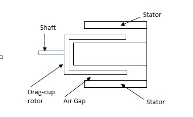
(b). Drag cup type motor :- For the drag cup rotor there are two air gaps. For the rotor a cup of non-magnetic conducting material is used. A stationary iron core is placed between the conducting cup to complete the magnetic circuit. The resistance of drag cup type is high and therefore, has high starting torque. Generally aluminium is used for cup.
Torque-speed characteristic:-
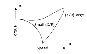
The torque speed characteristics of the two phase servomotor depends on ratio of reactance to resistance(X/R).
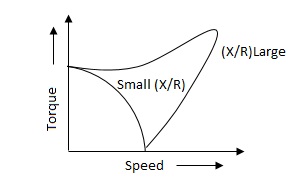
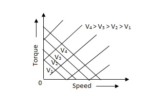
(i). For high ‘R’ and low X, the characteristic is linear and
(ii). For high X and low R, it becomes non-linear.
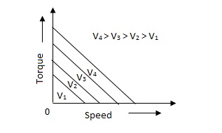
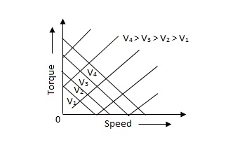
The torque-speed characteristic for various voltage is almost linear.
(b). D.C. Servomotor:-
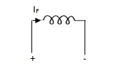
D.C. Servomotor are separately excited or permanent magnet dc servomotors. The armature of D.C. Servomotors is having large resistance and hence torque-speed characteristic is linear.
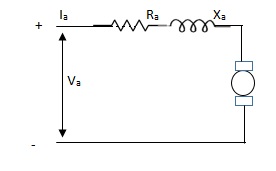
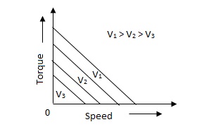
The above graph fig 5(b), clearly shows that the torque-speed characteristics is a function of control winding voltage as shown below.
T = mw + KVc -- (1)
Where T = Torque developed by motor
w = angular velocity
Vc = control winding voltage
Taking laplace of above equation (1),
T(S) = mS Q(S) + KVc - - (2)
T(S) = JS2Q(S) + FSQ(S) - - (3)
Above equation(3) is the dynamic eqution with,
J – moment of inertia
F – coefficient of friction of motor
From equation (2) and (3) the block diagram will be,

Q(S)/Vc = K/Js + F + m - - (4)
Comparison between A.C. Servomotor & D.C. Servomotor
| A.C. Servomotor | D.C. Servomotor |
|
|
|
1. | They are less efficient | They are more efficient |
2. | They have low power output | They have high power output |
3. | No noise so has smooth operation | These motors have noisy operation |
4. | They do not have any radio frequency noise | These motors have brushes so produce radio frequency noise |
5. | They are maintenance free because of no brushes and slip rings | For these motorsmaintenance is required. |
|
|
|
The Impulse signal, Ramp signal, unit step and parabolic signals are used as the standard test signals. All these signals are explained below.
Impulse Signal:-
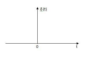 This signal have zero amplitude everywhere expect at the origin. Fig below shown the representation of Impulse signal.
The mathematical representations
A (t) = 0 for t ≠0
 dt = A e
Where A represent energy or area of the Laplace Transform of Impulse signal is
L [A (t) ]= A
The transfer function of a linear time invariantSystem is the Laplace transform of the impulse response of the system. If a unit impulse signal is applied to system then Laplace transform of the output c(s) is the transfer function G(s)
As we know G(s) = c(s)/R(S)
r(t) =  (t)
(t)
R(s) = L [ (t)] = 1
:. G(S) = C(s)
(b) Step signal:-
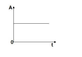
Step signal of size A is a signal that change from zero level to A in zero time and stays there forever.
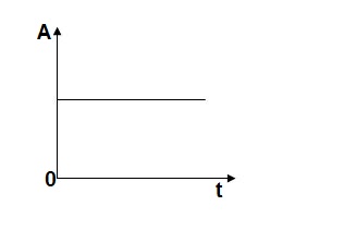
r(t)= A t >=0
=0 t<0
L[r(t)]= R(s) = A/s
(c) Ramp Signal:-
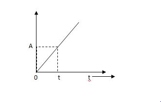 The vamp signal increase linearly with time from initial value of zero at t= 0 as shown in fig is below
r(t) = At t>=0
=0 t<0
A is the slope of the line The Laplace transform of ramp signal is
L[r(t)] = R(s) = A/s2
(d) Parabolic Signal:-
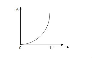
The instantaneous value of a parabolic signal varies as square of the time from an initial value of zero t=0. The signal representation in fig 14 below.
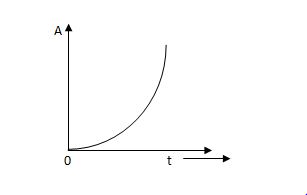
r(t) At2 t>=0
=0 t<0
Then Laplace Transform is given as
R(s) = L[At2] = 2A/s3
Reference Books :
- Modern Control Engineering by K.Ogata, Pearson Education.
2. Control Engineering by Kuo.
Unit 1
Introduction
A control system is a set of mechanical or electronic devices which control the other devices. In control system behaviours of the system is desired by differential equations
Classification of control system
(1) Open Loop control System:-
This is the loop of control system without any feedback. In this the control action is not dependent on the desired output.
 Fig. 1 open loop control system
Example of open Loop systems are The traffic signals, Automatic washing machine and in fields control d.c motor.
(2) Closed Loop control system:-
This is a type of control system with feedback In this type of system The control action is dependent on the desired output.
 Fig 2. Closed Loop control system
The error signal is again fed to controller to the error and get desired output.
Comparisons between open Loop and Closed Loop system
Open Loop System | Closed Loop system |
1.It does Not have any feedback. | 1. This system comprise of feedback |
2.As no feedback so easier to build. | 2.As it has feedback so difficult to build |
3.Theaccuracy of this system depends on the calibration of input. | 3.They are accuracy because of the feedback. |
4.Open Loop system are more stable. | 4.In closed Loop system stability depends on system components. |
5.optimization is not possible | 5. Optimization is possible |
6.These system are not reliable. | They are more reliable |
Transfer Function:-
The transfer function of a linear time invariant system is the ration of Laplace transform of the output to input.
(a) For open Loop system

G(s) = c(s)/R(s) -------(1)
 (b) For closed Loop system
+
-
G(s) – forward amplification
H(s) _ Reverse amplification
Above system is with negative feedback.
Positive feedback is used only in oscillators and other use is not known as discussing only negative feedback.
[ R(s) – c(s) H (S) ] G(s) = c(s)
R (s) G(s) = [1+G(s) H(s)] c(s)
C(s)/R(S) = G(S)/1+G(s) H(s)
S0, the transfer function of closed Loop system is
C(s)/ R(S) = G(s)/ 1+G(S) H(S) --------(2)
If numerator of above equation (2) is equalized to zero we get zeros of closed Loop Transfer function [G(S) = 0]
If dominator of equation (2) is equaled to zero we get polls of the closed loop transfer function [ 1+G(s) H(S) = 0]
1+ G(S) H(s) = 0 [ characteristic Equation]
Servomechanism is also called servo which is a device usually error sensing device connected as a feedback element to correct the action of a mechanism. Here instead of controlling a device by variable input signal, the device is controlled by feedback signal.
The input signal applied to such systems generate the required output which is compared again to the input signal. If the device achieves its desired output, there will be no longer the logical difference between the two signals. Hence, the primary task of servomechanism is to maintain the output of a system at the desired value in the presence of disturbances.
Types of Servomotors:-
(a). A.C. Servomotors
(b). D.C. Servomotors
(a). A.C.Servomotors:-
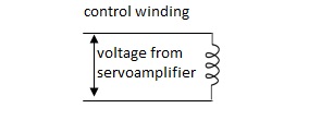
A.C servomotor is a two-phase ac induction motor. There are two windings in this motor, one is fixed or reference winding is supplied with a fixed voltage and frequency from a constant voltage source. Second winding is control winding with variable supply voltage of same frequency as reference winding but having a phase displacement of 900 electrical. A flux is induced due to the phase change which cuts the conducting bars of rotor and causes a time varying current, this current produces a time varying flux and reacts with the stator flux causing the rotor to rotate.
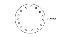
The rotor of A.C. Servomotos are of two types,
(a). Squirrel Cage Rotor
(b). Drag cup type rotor
(a). Squirrel cage rotor :- They have high resistance as the rotor is having large length and small diameter. The air gap here is kept small.

(b). Drag cup type motor :- For the drag cup rotor there are two air gaps. For the rotor a cup of non-magnetic conducting material is used. A stationary iron core is placed between the conducting cup to complete the magnetic circuit. The resistance of drag cup type is high and therefore, has high starting torque. Generally aluminium is used for cup.
Torque-speed characteristic:-
The torque speed characteristics of the two phase servomotor depends on ratio of reactance to resistance(X/R).
(i). For high ‘R’ and low X, the characteristic is linear and
(ii). For high X and low R, it becomes non-linear.
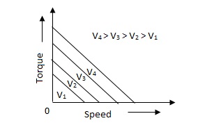
The torque-speed characteristic for various voltage is almost linear.
(b). D.C. Servomotor:-
D.C. Servomotor are separately excited or permanent magnet dc servomotors. The armature of D.C. Servomotors is having large resistance and hence torque-speed characteristic is linear.
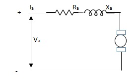
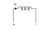
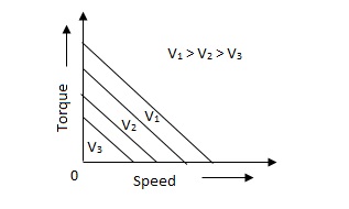
The above graph fig 5(b), clearly shows that the torque-speed characteristics is a function of control winding voltage as shown below.
T = mw + KVc -- (1)
Where T = Torque developed by motor
w = angular velocity
Vc = control winding voltage
Taking laplace of above equation (1),
T(S) = mS Q(S) + KVc - - (2)
T(S) = JS2Q(S) + FSQ(S) - - (3)
Above equation(3) is the dynamic eqution with,
J – moment of inertia
F – coefficient of friction of motor
From equation (2) and (3) the block diagram will be,

Q(S)/Vc = K/Js + F + m - - (4)
Comparison between A.C. Servomotor & D.C. Servomotor
| A.C. Servomotor | D.C. Servomotor |
|
|
|
1. | They are less efficient | They are more efficient |
2. | They have low power output | They have high power output |
3. | No noise so has smooth operation | These motors have noisy operation |
4. | They do not have any radio frequency noise | These motors have brushes so produce radio frequency noise |
5. | They are maintenance free because of no brushes and slip rings | For these motorsmaintenance is required. |
|
|
|
The Impulse signal, Ramp signal, unit step and parabolic signals are used as the standard test signals. All these signals are explained below.
Impulse Signal:-
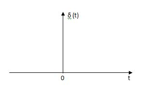 This signal have zero amplitude everywhere expect at the origin. Fig below shown the representation of Impulse signal.
The mathematical representations
A (t) = 0 for t ≠0
 dt = A e
Where A represent energy or area of the Laplace Transform of Impulse signal is
L [A (t) ]= A
The transfer function of a linear time invariantSystem is the Laplace transform of the impulse response of the system. If a unit impulse signal is applied to system then Laplace transform of the output c(s) is the transfer function G(s)
As we know G(s) = c(s)/R(S)
r(t) =  (t)
(t)
R(s) = L [ (t)] = 1
:. G(S) = C(s)
(b) Step signal:-
Step signal of size A is a signal that change from zero level to A in zero time and stays there forever.
r(t)= A t >=0
=0 t<0
L[r(t)]= R(s) = A/s
(c) Ramp Signal:-
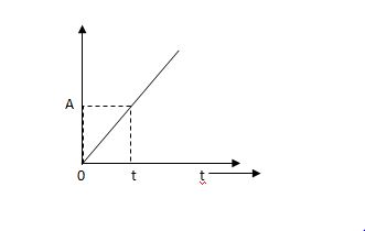 The vamp signal increase linearly with time from initial value of zero at t= 0 as shown in fig is below
r(t) = At t>=0
=0 t<0
A is the slope of the line The Laplace transform of ramp signal is
L[r(t)] = R(s) = A/s2
(d) Parabolic Signal:-
The instantaneous value of a parabolic signal varies as square of the time from an initial value of zero t=0. The signal representation in fig 14 below.
r(t) At2 t>=0
=0 t<0
Then Laplace Transform is given as
R(s) = L[At2] = 2A/s3
Reference Books :
- Modern Control Engineering by K.Ogata, Pearson Education.
2. Control Engineering by Kuo.